Here are the key points from the review paper:
- Variable pitch propellers allow
aircraft to adapt propeller blade angles to optimize performance across
diverse flight conditions. This offers benefits like expanded flight
envelope, enhanced maneuverability and fuel economy, prolonged engine
life.
- Two main types: hydraulic
(larger aircraft) and electric (smaller aircraft/UAVs). Hydraulic uses
oil pressure and flyweights to adjust pitch. Electric uses servo motor
and gearbox. Both use constant speed governors.
- Used with various engines:
turboprop, turboshaft, piston, wankel, DC motors. Matching propeller
with engine characteristics is important.
- Precise variable pitch control
is critical to realize benefits. PID control widely used but lacks
adaptability. More advanced methods like LQG, SMC, INDI, AMPC, neural
networks and reinforcement learning being explored for enhanced
robustness and adaptability.
- Benefits: improves aircraft endurance, maneuverability, fuel economy. Meets needs for propulsion system similarity studies.
- Key challenges: insufficient
system modeling, partial propeller-engine matching, impact of external
unsteady factors. Need for adaptive, intelligent control systems that
can learn and optimize online in face of uncertainties.
In summary, variable pitch propellers are an enduring but dynamically evolving technology offering substantial benefits if paired with sophisticated control systems. Addressing modeling, compatibility and external factor challenges through data-driven and adaptive techniques can further advance their capabilities.
Propeller Basics
A propeller typically consists of the following key components:
-
Hub: The central part of the propeller, which
connects to the aircraft's engine or the propulsion system. The hub is
mounted on the engine's driveshaft and provides the structural support
for the blades.
-
Blades: Propellers have two or more blades attached
to the hub. These blades are aerodynamically designed to generate thrust
when they rotate. The number of blades can vary depending on the type
of aircraft and its specific requirements.
-
Blade Root: The part of the blade that attaches to
the hub. It's the base of the blade and is designed to withstand the
mechanical stresses associated with propeller rotation.
-
Blade Tip: The outermost part of the blade, which
generates the highest speed and thrust as it moves through the air.
Blade tips are often shaped to minimize drag and improve efficiency.
-
Pitch: The angle at which the blades are set
relative to the plane of rotation. Adjusting the pitch allows the pilot
or operator to control the amount of thrust generated by the propeller.
-
Spinner: In some cases, a spinner is used to cover
the hub and the base of the blades for aerodynamic reasons and to
improve airflow around the propeller.
-
Propeller Governor: An optional component that helps
control the engine's RPM (revolutions per minute) by adjusting the
pitch of the blades automatically to maintain a constant RPM.
-
Blade Twist: Propeller blades are often twisted
along their length to optimize their performance. The twist helps
distribute the load evenly along the blade and improve efficiency.
The design of a propeller can vary significantly depending on the
specific application, whether it's for an aircraft, a boat, or another
type of vehicle. The dimensions, shape, and materials used in a
propeller are carefully engineered to maximize efficiency and
performance for the intended use.
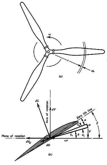
The two quantities of interest are the thrust (T) and the torque (Q). We
can write expressions for these for a small radial element (dr) on one of
the blades:


where
 and
and 
It is possible to integrate the relationships as a function of r with the
appropriate lift and drag coefficients for the local airfoil shape, but determining
the induced upwash (ai)
is difficult because of the complex helical nature of the trailing vortex
system. In order to learn about the details of propeller design, it is necessary
to do this.
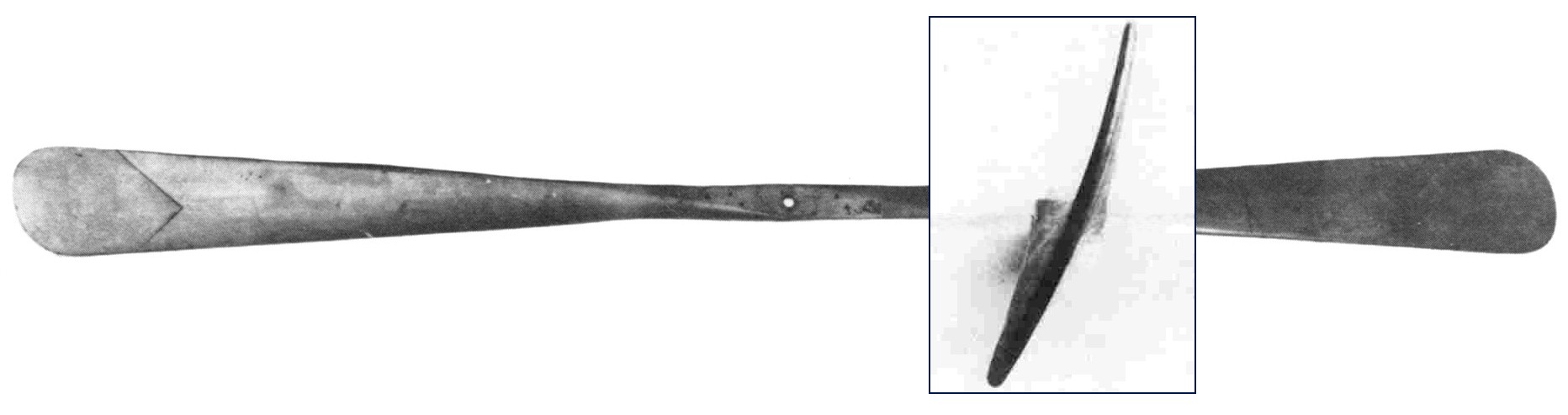
The Wright brothers, Orville and Wilbur Wright, are credited with
inventing and building the world's first successful powered aircraft in
the early 20th century. While they are well-known for their pioneering
work in aviation, they also made important contributions to propeller design.
The Wright brothers understood that a well-designed propeller was
crucial for the efficient and controlled flight of their aircraft. They
conducted extensive experiments to determine the optimal shape and
dimensions for their propellers. In 1903, they were granted a patent for
their propeller design.
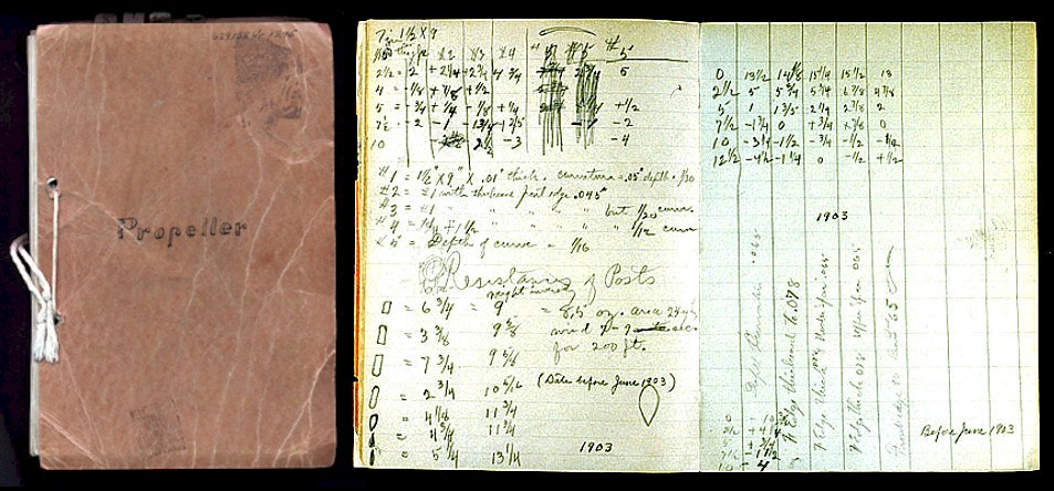 |
Wright Propeller Lab Workbook
|
The patent for the Wright brothers' propeller design is contained in the "Wright Flyer"
known as U.S. Patent No. 821,393, and it was filed on March 23, 1903,
just a few months before their historic first powered flight on December
17, 1903. The patent described the
innovative features of their propeller design, which included a twisted airfoil shape along the
length of the blade, a unique curvature, and a specific method of
construction.
This
modern theory is slightly different from the theory developed by the
Wright’s to design their propellers.
 |
Wright Flyer Propeller, end view, and Dual Mounting Side View
|
Propeller Propulsion System
The details of propeller propulsion are very
complex because the propeller is like a rotating wing. The Wright brothers are generally credited with being the first ones to look at the problem this way.
The Wright propellers had 2 blades. The blades were designed to be long
and thin, and a cut through the blade perpendicular to the long
dimension gives an airfoil shape. Because the blades rotate, the tip
moves faster than the hub.
So, to make the propeller efficient, the blades are twisted from hub
to tip. The angle of attack of the airfoils at the tip is lower than at
the hub because it is moving at a higher velocity than the hub. Of
course, these variations make analyzing the airflow through the
propeller a very difficult task. Leaving the details to the
aerodynamicists, let us assume that the spinning propeller acts like a
disk through which the surrounding air passes (the yellow ellipse in the
schematic).
From airfoil theory, we know that the pressure over the top of a
lifting wing is lower than the pressure below the wing. A spinning
propeller sets up a pressure lower than free stream in front of the
propeller and higher than free stream behind the propeller. Downstream
of the disk the pressure eventually returns to free stream conditions.
But at the exit, the velocity is greater than free stream because the
propeller does work on the airflow. We can apply Bernoulli’s equation to
the air in front of the propeller and to the air behind the propeller.
But we cannot apply Bernoulli’s equation across the propeller disk
because the work performed by the engine violates an assumption used to
derive the equation.
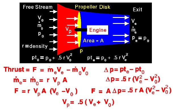
Simple Momentum Theory
Turning to the math, from the basic thrust equation, the amount of thrust depends on the mass flow rate through
the propeller and the velocity change through the propulsion system.
Let us denote the free stream conditions by the subscript “0”, the
conditions at the propeller by the subscript “p”, and the exit
conditions by the subscript “e”. The thrust (F) is equal to the mass flow rate (mdot) times the difference in velocity (V).
F = [mdot * V]e – [mdot * V]0
The mass flow through the propulsion system is a constant, and we can
determine the value at the plane of the propeller. Since the propeller
rotates, we can define an area (A) that is swept out by the propeller of blade length (L). Through this area, the mass flow rate is density (r) times velocity (Vp), times area.
mdot = r * Vp * A
Substitute this value for the mass flow rate into the thrust equation
to get the thrust in terms of the exit velocity, entrance velocity, and
velocity through the propeller.
F = r * Vp * A * [Ve – V0]
We can use Bernoulli’s equation to relate the pressure and velocity
ahead of and behind the propeller disk, but not through the disk. Ahead
of the disk the total pressure (pt0) equals the static pressure (p0) plus the dynamic pressure (.5 * r * V0 ^2).
pt0 = p0 + .5 * r * V0 ^2
Downstream of the disk,
pte = p0 + .5 * r * Ve ^2
At the disk itself the pressure jumps
delta p = pte – pt0
Therefore, at the disk,
delta p = .5 * r * [Ve ^2 – V0 ^2]
The force on the propeller disk is equal to the change in pressure times the area (force/area x area = force)
F = delta p * A
If we substitute the values given by Bernoulli’s equation, we obtain:
F = .5 * r * A * [Ve ^2 – V0 ^2]
Combining the two expressions for the the thrust (F) and solving for Vp;
Vp = .5 [Ve + V0]
Note that this thrust is an ideal number that does not account for
many losses that occur in practical, high-speed propellers (like tip
losses). The losses must be determined by a more detailed propeller
theory, which is beyond the scope of these pages. The complex theory
also provides the magnitude of the pressure jump for a given geometry.
The simple momentum theory, however, provides a good first cut at the
answer and could be used for a preliminary design.
Equations to characterize the Propeller
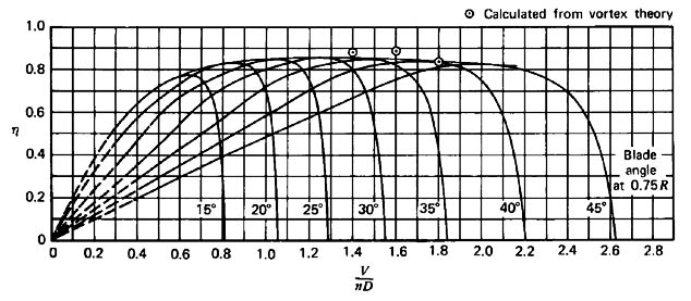 |
| Typical propeller efficiency curves as a function of advance ratio (J=uo/nD)
and blade angle(McCormick, 1979) |
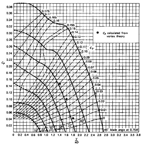 |
| Typical propeller power curves as a function of advance ratio (J=uo/nD)
and blade angle (McCormick, 1979). |
The blade angle can be adjusted in a variable pitch propeller to optimize efficiency over range of speeds. This can be extended to negative angles for negative speeds for braking and maneuvering as in maneuverable quadcopters, or braking during landing for VSTOL aircraft.
In aerodynamics and propeller theory, the advance ratio (J) is a
critical parameter that characterizes the performance of a propeller. It
is defined as:
J = (V / nD)
Where:
- J is the advance ratio
- V is the velocity of the aircraft or the inflow velocity at the propeller disc
- n is the rotational speed of the propeller (in revolutions per minute, RPM)
- D is the diameter of the propeller disc
The advance ratio provides a way to describe the relative importance
of the forward speed of the aircraft (or inflow velocity) and the
rotational speed of the propeller in determining the performance of the
propeller.
The propeller power curve is a plot of the power required or power
produced by a propeller as a function of the advance ratio (J). The
shape of this curve depends on several factors, including the blade
angle, airfoil shape, and other design parameters.
Typically, the propeller power curve has the following characteristics:
-
Minimum Power Point (MPP): There is a point on the
curve where the power required to turn the propeller is minimized for a
given advance ratio. This is often the point of peak propeller
efficiency. The propeller operates most efficiently at or near this
point.
-
Climbing and Descending Segments: The power curve
will have climbing and descending segments on either side of the MPP. In
the climbing segment, as the advance ratio decreases (J increases),
more power is required to turn the propeller due to increased airspeed.
In the descending segment, as the advance ratio increases (J decreases),
more power is required due to decreased airspeed.
-
Maximum Power Point (Max Power): At the highest
advance ratios, the power required to turn the propeller increases
significantly, leading to a maximum power point. This is often
encountered in high-speed flight or when the propeller is operating at
high angles of attack.
The blade angle plays a crucial role in shaping the power curve.
Blades with different angles of attack will have different power curves.
A propeller's design aims to optimize the blade angle and airfoil shape
to achieve the desired performance characteristics across a range of
operating conditions. This is why variable pitch propellers expand and extend operating characteristics.
It's important to note that propeller performance is also influenced
by factors such as altitude, temperature, and humidity, which can affect
air density and, consequently, the performance of the propeller.
For specific power curves and detailed analysis, you would need to
refer to the data and research presented in McCormick's 1979 work or
other relevant sources on propeller theory and performance.
Medium Altitude Long Endurance UAVs
there are some medium-altitude, long-endurance (MALE) unmanned aerial vehicles (UAVs) that utilize variable pitch propellers:
- MQ-9 Reaper: A widely used MALE
UAV developed by General Atomics Aeronautical Systems. It uses a variable pitch pusher
propeller powered by a TPE331-10 TURBOPROP ENGINE. VPP control is integrated into the engine. This enhances its
endurance and efficiency.
| Max Altitude: |
50,000 ft (15240m) |
| Max Endurance: |
27 hr |
| Max Air Speed: |
240 KTAS |
- Heron TP: An Israeli MALE UAV
with a variable pitch pusher propeller.
endurance of over 45
hours
altitude ceiling of 30,000 ft. - Bayraktar TB2: A Turkish MALE
UAV that employs a variable pitch propeller system. It has demonstrated
over 27 hours of endurance.
- CH-5: A Chinese MALE UAV by
China Aerospace Science and Technology Corporation. Its variable pitch
propellers are powered by a 170 hp turbocharged piston engine, providing
long endurance.
Max Altitude = 29,528 ft
Max Endurance = 21 hr
Max Airspeed = 298 mph - MQ-1C Gray Eagle: An extended range version of the Predator UAV using a variable pitch pusher propeller.
| Max Altitude: |
29,000 ft (8839.2m) |
| Max Endurance: |
25 hr |
| Max Air Speed: |
167 KTAS |
Variable pitch propellers allow these MALE UAVs to achieve the high endurance, efficiency and flight envelope they require for their surveillance and reconnaissance missions. The technology is well suited to balance the demands of both loitering at altitude and efficient cruise flight.
Current Pitch Control Methods
The specific control algorithms used for variable pitch propellers in MALE UAVs are often proprietary to the manufacturers. However, based on the general research into variable pitch control, some commonly used approaches include:
- PID control: The most widespread
method using proportional, integral and derivative terms to achieve the
desired pitch angle. Provides simplicity but lacks adaptability.
- Fuzzy logic control: Allows pitch control based on imprecise inputs and linguistic control rules. Provides some robustness.
- Neural networks: Used to model
the complex propeller dynamics and provide predictive pitch control.
Offers ability to learn system behavior.
- Model predictive control:
Optimizes pitch angles by predicting system behavior over a time horizon
using a model. Handles constraints well.
- Reinforcement learning:
Optimizes a pitch control policy to maximize reward signals related to
objectives like efficiency. Enables online learning.
- Hybrid methods: Combining
model-based and learning-based techniques for balanced performance. For
example, neural networks with PID or reinforcement learning with model
predictive control.
The choice of control algorithm depends on factors like the propeller setup, aircraft performance objectives, environmental conditions, and computational capabilities. Many MALE UAVs likely use proprietary implementations of hybrid control techniques to get the adaptation benefits while ensuring stability and reliability. The ability to optimize efficiency online for long missions would be particularly beneficial.
VPQ unique capabilities
On smaller commercial drones, which have become popular in recent years, the installation
of variable pitch propellers is being considered and researched for
industrial applications such as large drones and flying mobility. A
variable-pitch propeller not only provides higher responsiveness than
control by rotational speed alone, but also expands the thrust that can
be achieved by optimizing the combination of rotational speed and pitch
angle.
A
Variable Pitch Quadcopter (VPQ) is a type of quadcopter that features
variable pitch propellers. These propellers can change their pitch angle
during flight, which allows for more precise control and greater
maneuverability compared to traditional fixed-pitch quadcopters. The
Aerospace Controls Laboratory, typically found in universities or
research institutions, may be involved in the development and research
of such advanced aerial vehicles.
Here are some key aspects of a Variable Pitch Quadcopter and how it differs from a standard quadcopter:
-
Variable Pitch Propellers:
- Variable pitch propellers have the ability to adjust the angle of their blades dynamically during flight.
- By changing the pitch of the propellers, a VPQ can generate varying
amounts of thrust, making it possible to achieve complex maneuvers and
control in different flight conditions.
-
Enhanced Maneuverability:
- Variable pitch allows for rapid changes in thrust and torque, making it more agile and responsive than fixed-pitch quadcopters.
- It can perform acrobatic maneuvers, recover from disturbances, and hover more precisely.
-
Versatility:
- VPQs can adapt to different flight regimes, from hovering and slow flight to high-speed forward flight.
- This adaptability makes them suitable for a wide range of applications, from search and rescue to surveillance.
-
Research and Development:
- Aerospace Controls Laboratories often focus on the development and testing of advanced aerial systems like VPQs.
- Research goals may include improving flight control algorithms,
optimizing power efficiency, enhancing stability in challenging
environments, and exploring new applications.
-
Control Systems:
- VPQs require sophisticated control systems to manage the variable pitch propellers effectively.
- These control systems often involve advanced algorithms, sensors,
and real-time computing to adjust propeller pitch based on flight
conditions.
-
Applications:
- VPQs have potential applications in various fields, including
military and defense, aerial photography, environmental monitoring, and
agricultural surveys.
-
Challenges:
- Designing and building a VPQ can be challenging due to the complexity of the variable pitch mechanism and control system.
- Ensuring the safety and reliability of such aircraft is critical.
The specific research and development projects in an Aerospace
Controls Laboratory involving a Variable Pitch Quadcopter may vary, but
they typically revolve around improving the performance, control, and
applications of these advanced aerial vehicles.
In his thesis, Mark Cutler explores the benefits of using
variable-pitch propellers on quadrotor helicopters. He argues that
variable-pitch propellers can overcome some of the limitations of
fixed-pitch propellers, such as the limited actuator bandwidth and the
types of maneuvers possible.
Cutler presents a detailed analysis
of the potential benefits of variable-pitch propellers, and supports his
analysis with experimental testing. He also presents a nonlinear,
quaternion-based control algorithm for controlling a variable-pitch
quadrotor helicopter.
Cutler's thesis is a valuable contribution
to the field of quadrotor helicopter design and control. His work shows
that variable-pitch propellers can significantly improve the performance
and capabilities of quadrotor helicopters.
Here are some of the key findings of Cutler's thesis:
- Variable-pitch propellers allow for efficient generation of negative thrust, which is not possible with fixed-pitch propellers.
- Variable-pitch propellers substantially increase the maximum rate of thrust change.
- The use of variable-pitch propellers enables new types of maneuvers, such as aggressive forward flight and agile hovering.
- Cutler's
nonlinear, quaternion-based control algorithm is able to effectively
control a variable-pitch quadrotor helicopter, even under challenging
conditions.
Cutler's thesis has had a significant impact on
the field of quadrotor helicopter design and control. His work has
inspired other researchers to develop new variable-pitch quadrotor
helicopters and control algorithms. Variable-pitch quadrotor helicopters
are now widely used in a variety of applications, including aerial
photography, inspection, and delivery.
Optimal variable pitch control methods
Optimal variable pitch propeller control methods for Medium Altitude
Long Endurance (MALE) Unmanned Aerial Vehicles (UAVs) are crucial for
achieving efficient and effective flight performance. Variable pitch
propellers allow UAVs to adapt to different flight conditions, maximize
endurance, and improve overall mission capabilities. Here are some
optimal control methods for variable pitch propellers on MALE UAVs:
-
Constant-Speed Propeller Control (CSPC): This
control method maintains a constant rotational speed of the propeller
blades. This is suitable for cruising and maintaining a fixed airspeed,
as it provides consistent thrust. It can be combined with other control
methods for better performance.
-
Variable-Pitch Control (VPC): VPC allows for the
adjustment of the propeller blade pitch angle in real-time. By varying
the pitch angle, the UAV can optimize thrust, efficiency, and speed for
different flight phases. For example, a high pitch angle can be used for
climbing, while a low pitch angle can be used for cruising.
-
Constant Angular Velocity Control (CAVC): This
method maintains a constant angular velocity (rpm) of the propeller,
which is particularly useful for applications where a fixed rotational
speed is critical, such as in surveillance missions requiring steady
camera footage.
-
Optimal Control Algorithms: Implementing advanced
control algorithms, such as PID (Proportional-Integral-Derivative)
controllers or more sophisticated model-based controllers, can help
optimize variable pitch propeller performance. These algorithms can
continuously adjust the propeller pitch based on various parameters such
as airspeed, altitude, and payload weight to maximize efficiency and
endurance.
-
Flight Control System Integration: Integration with
the overall flight control system is essential. Variable pitch propeller
control should work in harmony with other flight control elements like
the autopilot, navigation system, and mission-specific software. This
integration allows for coordinated and optimized control strategies.
-
Mission-Adaptive Control: Develop control algorithms
that adapt to the specific mission requirements of the MALE UAV. For
instance, for a reconnaissance mission, the control system may
prioritize endurance and altitude holding, while for a search-and-rescue
mission, it may prioritize rapid climbing and descent.
-
Energy Management: Implement energy management
strategies to balance energy consumption and generation. This includes
optimizing the use of onboard power sources (e.g., batteries or
generators) and the propulsion system to maximize overall endurance.
-
Real-Time Sensor Feedback: Utilize real-time data
from onboard sensors (e.g., airspeed, altitude, temperature) to adjust
the variable pitch propeller settings on the fly. This allows the UAV to
adapt to changing environmental conditions and optimize its performance
accordingly.
-
Fail-Safe Mechanisms: Incorporate fail-safe
mechanisms that can revert the variable pitch propeller to a safe
configuration in case of system malfunctions or emergencies, ensuring
the UAV can safely return to base or complete its mission.
-
Testing and Simulation: Extensive testing and
simulation are essential to fine-tune and validate control methods for
variable pitch propellers. This helps in identifying and addressing
potential issues before deployment.
Suggested Approaches to Optimality
This review paper does not explicitly propose a single optimal variable pitch control method. However, based on the analysis and discussion presented, some key recommendations can be summarized:
- Adaptive and intelligent control
methods are needed to handle changing dynamics, uncertainties and
disturbances. This includes techniques like incremental nonlinear
dynamic inversion (INDI), adaptive model predictive control (AMPC), and
reinforcement learning (RL).
- Hybrid hierarchical approaches
combining model-based and learning-based techniques appear promising to
balance performance, stability and adaptability. For example, INDI with
neural networks or RL combined with model predictive control.
- Control techniques that can
continuously learn and optimize online in real-time flight are critical
to maximize efficiency across long missions in dynamic conditions. RL
and adaptive critics are highlighted in this regard.
- Addressing challenges in
modeling, engine-propeller compatibility, and external factors is
pivotal through data-driven and adaptive control techniques. This
reduces reliance on fixed analytical models.
- Cascaded, hierarchical control
architectures allowing integrated management of various sub-systems and
flight modes are beneficial for comprehensive control.
In summary, the paper recommends adaptive, intelligent and hierarchical control schemes with online learning and optimization capabilities as the most promising direction for advanced variable pitch propeller control on complex aircraft. A mix of model-based and data-driven techniques is advisable.
Adaptive
and intelligent control methods
Adaptive
and intelligent control methods for variable pitch propellers (VPP) are
crucial to efficiently handle changing dynamics, uncertainties, and
disturbances in marine or aerospace applications. These techniques help
optimize performance and ensure stability. Here's an overview of how
each of the methods you mentioned can be applied:
-
Incremental Nonlinear Dynamic Inversion (INDI):
INDI is a model-based control technique that can be adapted for VPP control. It involves the following steps:
- System Modeling: Develop a dynamic model of the VPP system, including the propeller, power source, and any other relevant components.
- Dynamic Inversion: Invert the dynamic model to obtain the desired control inputs that will produce the desired system response.
- Adaptation: Incorporate adaptive mechanisms to
account for changing dynamics and uncertainties. This can involve online
parameter estimation or model adaptation algorithms.
- Disturbance Rejection: Implement techniques for handling disturbances, such as disturbance observers or feedforward control.
INDI can effectively handle changing dynamics by continuously
updating the control inputs based on the current system state and
adapting to uncertainties and disturbances.
-
Adaptive Model Predictive Control (AMPC):
AMPC is a control strategy that uses a predictive model of the system to
optimize control inputs over a finite time horizon. For VPP, AMPC can
be applied as follows:
- Model Development: Create a predictive model of the VPP system that captures its dynamics and uncertainties.
- Prediction and Optimization: Predict the future
system behavior over a horizon and optimize control inputs to achieve
desired performance while considering disturbances.
- Adaptation: Incorporate adaptive elements into the
model to account for changing dynamics and uncertainties. This can
include updating model parameters or using adaptive constraints in the
optimization.
AMPC's predictive nature allows it to handle changing dynamics and
uncertainties by continuously adjusting the control inputs based on the
updated model and feedback.
-
Reinforcement Learning (RL):
RL is a data-driven approach that can be applied to VPP control,
although it typically requires a substantial amount of data for
training. Here's how RL can be used:
- Environment Modeling: Create a simulator or a digital twin of the VPP system to serve as the RL environment.
- Training: Train an RL agent to interact with the
environment and learn optimal control policies through exploration and
reward maximization.
- Adaptation: RL agents inherently adapt to changing
dynamics and disturbances during training. However, fine-tuning or
retraining may be necessary as the system evolves or encounters
significant changes.
RL is particularly effective when dealing with complex and uncertain
VPP systems, but it requires careful consideration of safety and
exploration during training.
In summary, these control methods—INDI, AMPC, and RL—can be adapted
for variable pitch propeller control to address changing dynamics,
uncertainties, and disturbances. The choice of method depends on the
specific application, available data, and computational resources, as
each method has its strengths and limitations.
Potential Performance Gains
Adopting optimal and adaptive variable pitch control techniques could potentially provide significant performance improvements compared to conventional fixed gain controllers:
- Fuel efficiency gains of 10-20%
reported in some studies by optimizing pitch angles for minimum power
consumption across flight envelopes.
- Increased aircraft endurance by 5-15% through power optimization and expanded flight envelopes.
- Enhanced maneuverability and
precision in tracking control inputs due to faster pitch actuation
response and reversal capabilities.
- Ability to handle constraints such as engine speed limitations more effectively by predictive control algorithms.
- Up to 30-50% reduction in
modeling errors and uncertainties by relying on data-driven adaptation
rather than fixed analytical models.
- Improved stability and robustness in aggressive maneuvers and turbulence by adaptation to dynamic conditions.
- Potential elimination of trim requirements and simpler autopilot integration by neutralizing modeling errors adaptively.
The scale of improvements depends on the specific aircraft, with most gains coming from long-endurance UAVs and multi-rotors. But even manned aircraft could see benefits in efficiency and handling qualities from optimal variable pitch control. The key is having the advanced control architectures to fully exploit the capabilities.