New, portable antenna could help restore communication after disasters | Stanford University School of Engineering
When an earthquake, flood, or other disaster strikes a region, existing communication infrastructure such as cell phone and radio towers are often damaged or destroyed. Restoring emergency communications as quickly as possible is vital for coordinating rescue and relief efforts.
Researchers at Stanford University and the American University of Beirut (AUB) have developed a portable antenna that could be quickly deployed in disaster-prone areas or used to set up communications in underdeveloped regions. The antenna, described recently in Nature Communications, packs down to a small size and can easily shift between two configurations to communicate either with satellites or devices on the ground without using additional power.
“The state-of-the-art solutions typically employed in these areas are heavy, metallic dishes. They’re not easy to move around, they require a lot of power to operate, and they’re not particularly cost-effective,” said Maria Sakovsky, an assistant professor of aeronautics and astronautics at Stanford. “Our antenna is lightweight, low-power, and can switch between two operating states. It’s able to do more with as little as possible in these areas where communications are lacking.”
Two functions in one antenna
The researchers developed the antenna with an approach typically used to design devices that are being deployed in space. Because of fuel and space limitations, technology being sent into orbit must be very lightweight and packaged as small as possible. Once the items are in orbit, they unfold into the proper shape for use. The researchers wanted their antenna to be similarly collapsible and lightweight.
The antenna designed by Sakovsky and her colleagues at AUB, including Joseph Costantine, Youssef Tawk, and Rosette Maria Bichara, is made of fiber composites (a material often used in satellites) and resembles a child’s finger-trap toy, with multiple strips of material crossing in spirals. Just like any helix-based antenna, conductive material running through the antenna sends out signals, but thanks to its unique structure, the researchers can adjust the pattern and power of those signals in the new antenna by pulling it into longer shapes or shorter shapes.
“Because we wanted the antenna to be able to collapse into a packable shape, we started with this structure that led us to a very untraditional antenna design,” Sakovsky said. “We’re using shapes that have never been used on helical antennas before, and we’ve shown that they work.”
At its most compact, the antenna is a hollow ring that stands just over 1 inch tall and about 5 inches across – not much larger than a bracelet – and weighs 1.4 ounces. In this shape, it’s able to reach satellites with a high-power signal sent in a particular direction. When stretched out to about a foot tall, the antenna sends a lower power signal in all directions, more like a Wi-Fi router.
Shifting between these two states is as simple as pulling or pushing on the antenna. These movements don’t even need to be particularly precise because, once the antenna is moved past a certain point, the structure snaps to the right position. The specific size and shape of the antenna design will determine which frequencies those two states communicate across.
“The frequency you want to operate at will dictate how large the antenna needs to be, but we’ve been able to show that no matter what frequency you operate at, you can scale this design principle to achieve the same performance,” Sakovsky said.
The fabricated prototype was tested for deployment and structural performance at Stanford and its electromagnetic radiation characteristics at the antenna measurement facilities at AUB.

Applications in orbit
To be deployed in the field, the antenna would need to be paired with a transceiver to send and receive signals, a ground plane to reflect radio waves, and other electronics, but the whole package would still only weigh about 2 pounds, Sakovsky said. And the antenna’s unique dual functionality means that it could replace multiple heavier antennas in areas where deployment is a challenge.
That includes uses in disaster-struck and underdeveloped areas, but also, potentially, in space. Sakovsky and her colleagues are considering adapting their design for satellite communications, allowing satellites to use the same antenna to talk to each other and to talk to the ground.
“We don’t have a lot of spare operating power, volume, or mass on our spacecraft either,” Sakovsky said. “This holds a lot of potential for replacing multiple antennas on a satellite with a single one.”
Sakovsky is affiliated with the Stanford SystemX Alliance
A multi-stable deployable quadrifilar helix antenna with radiation reconfigurability for disaster-prone areas
Reconfigurable fiber-reinforced polymer antenna
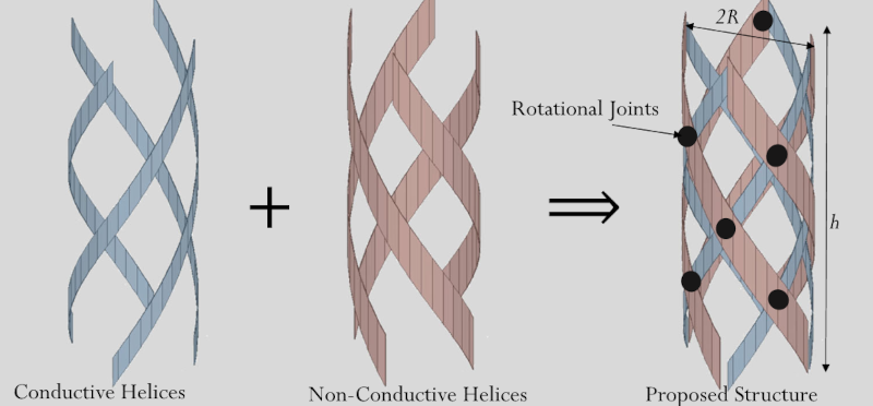
The proposed structure is composed of four conductive strips wound counter-clockwise and four dielectric strips wound clockwise. The strips are interconnected using non-conductive rotational joints as shown in Fig. 2a. The joints enable the whole structure to simultaneously vary its height, h, and radius, R. The reconfigurable deployable antenna concept proposed here is illustrated in Fig. 2b. The proposed design is based on a quadrifilar helix antenna where the dielectric strips act as a structural support for the conductive helices and enable reconfiguration between states. The deformation of the helical structure is enabled through the bending and twisting of the strips and any length changes are relatively small29. As a result, the height of the helix, h, is related to its radius, R, using (1)29, where l is the length for each of the strips and N is the number of turns.
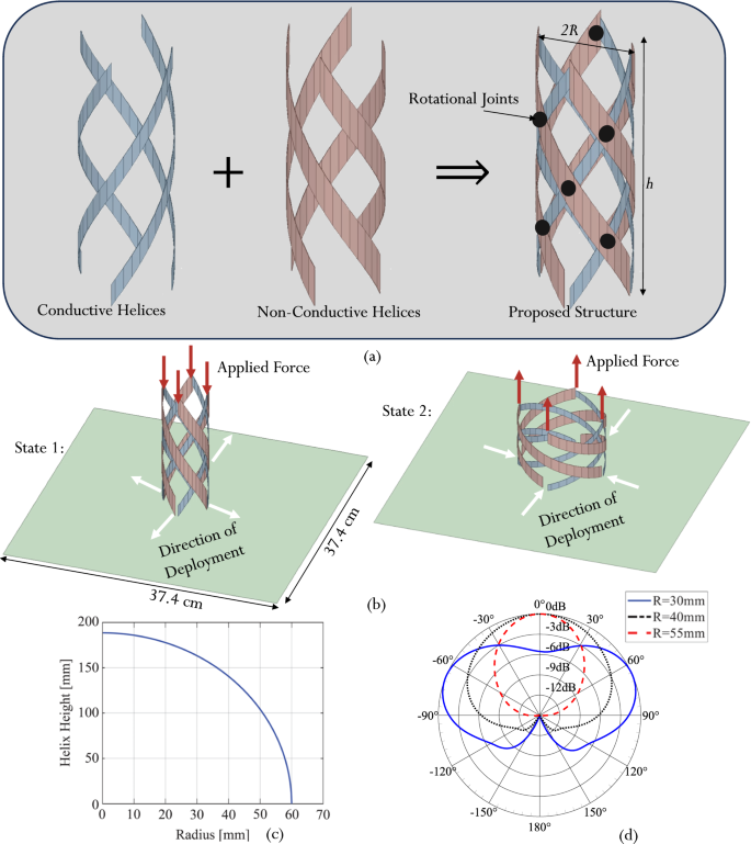
a Antenna structure and topology. b Antenna reconfiguration concept and mechanism. c Relationship between helix height and radius for the length of the strip (l = 188.5 mm) and the total number of turns (N = 0.5). d Radiation pattern variation as a function of radius at 1.1 GHz.
Reconfiguration is executed by applying a vertical force on the tips of the strips that make up the structure as depicted in Fig. 2b. This force enables the eight strips to slide along the structure’s ground plane by following the four arrows that are parallel to the ground plane. Applying a force in the (−z) direction reduces the height of the helix and increases its radius while applying a force in the (+z) direction reduces the radius of the helix and increases its height. The relationship between the helix height and radius for the length of the strip (l = 188.5 mm) and the number of turns (N = 0.5 turns) is presented in Fig. 2c.
In the remainder of this section, we identify the particular combinations of radius and height (i.e., helix geometries) that result in the desired radiation pattern and polarization reconfiguration. Accordingly, we then present a material and structural concept to ensure the selected helix geometries correspond to the minima of the deformation strain energy of the structure – making these geometries stable states that require no external energy to be maintained.
Two distinct operational states
The electromagnetic response of the proposed QHA was assessed by simulations for various radius and height combinations as per Fig. 2c. These different geometries were simulated using Ansys High-Frequency Structure Simulator (HFSS)30, discussed in the Methods section. Supplementary Table 1 provides the detailed antenna performance metrics as a function of the helix geometry. It was found that for a radius (R) less than 25 mm, the antenna structure is not well matched. For 25 mm <R < 35 mm, the antenna exhibits a close to omnidirectional pattern. A radius between 45 mm <R < 55 mm allows the antenna to exhibit a directional pattern with circularly polarized radiation behavior. For R > 55 mm, the antenna design is no longer matched.
The simulated and normalized radiation patterns representing these different operating regimes are shown for three different radii in Fig. 2d. It is important to note that for a radius between 35 mm and 45 mm, the antenna starts its operational transition from an omnidirectional pattern to a directional one. Since the conductive strip length remains constant throughout the reconfiguration, the operating frequency remains within the antenna bandwidth between 1 GHz and 1.2 GHz. Accordingly, two distinct antenna operating states are identified. These states reconfigure the radiation characteristics of the antenna. State 1 is characterized by a radius of R = 30 mm and an almost omnidirectional radiation pattern. These characteristics make it suitable for terrestrial communications between various devices deployed in a low-infrastructure or disaster-stricken area. On the other hand, State 2 is characterized by a radius of around R = 55 mm with a directive radiation pattern and circular polarization, making it ideal for satellite communications.
The corresponding simulated magnitude of the 3D radiated electric field pattern for state 1 and state 2 are presented in Fig. 3a, b at f = 1.1 GHz. The 2D left- and right-handed circularly polarized gain patterns along the Y − Z plane are presented for state 2 in Fig. 3c. A cross-polarization of 41.68 dB is obtained along the direction of maximum radiation at θ = 0°. This confirms the circular polarization purity of the antenna in state 2.
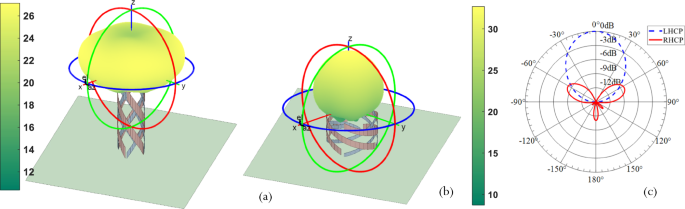
a Antenna in state 1 with its 3D radiated electric field magnitude in dB. b Antenna in state 2 with its 3D radiated electric field in dB. c The simulated Left Hand Circularly Polarized (LHCP) and Right Hand Circularly Polarized (RHCP) two-dimensional radiation pattern for State 2, proves that in State 2 the antenna is LHCP.
Multi-stable composite structure
Each helix is composed of initially flat strips of glass fiber and epoxy composites with an embedded conductive mesh. These strips are interconnected using rotational joints into a helical lattice as discussed in the Methods section. As the helix is reconfigured between various geometries, the strips undergo bending and twisting31, thereby changing the strain energy stored in the structure due to the elastic deformation of the material. The stored strain energy, U, results in forces acting along the axis of the helix according to Castigliano’s theorem32,
These forces deform the structure towards its minimum energy configuration. The energy minima are the stable points of the structure, where the restoring forces are Fa = 0 and the structure can maintain its geometry without external power. In the case that the force pushes the structure towards its minimum or maximum radius, there are additional stable points at these extremes. We leverage such behavior in our study to enable the low-energy, user-centric reconfiguration of the structure. The desired geometries are reliably achieved as axial forces due to the stored strain energy and will always push the structure to the minimum energy configuration. No DC power is required for actuators to maintain stable geometries.
The use of fiber-reinforced polymer (FRP) composites for the strip material has been shown in the literature to yield a rich design space for stability31. The stored strain energy can be predicted as a function of material properties and helix geometry using a 2D analytic model accounting for longitudinal and transverse bending as well as twisting in the strips. A detailed discussion of the design parameters is presented in the Methods section. We demonstrate that we can use the fiber orientation of the composite material relative to the strip length, θ, to induce a multi-stable response. Figure 4a demonstrates the use of fiber orientation in the strips to increase the number of stable points for a helix made of glass-fiber-reinforced epoxy material. It is found that a fiber angle of 8° results in two stable points at radii corresponding to States 1 and 2, thereby successfully coupling mechanical and electromagnetic reconfiguration. The third stable point at the minimum radius is not used in practice. At this fiber angle, the FRP material has low torsional stiffness as well as high material coupling between bending and twisting deformations. The helical strips twist significantly to enable multi-stability. The stable radii are measured when the QHA is integrated with its ground plane. These agree well with the predictions in Fig. 4a with small deviations due to manufacturing imperfections, the physical width of the strips, and integration with the ground plane. The antenna is shown in its two stable states in Fig. 4b. The resulting dimensions of the antenna structure in the two stable operating states with radii of R = 30 mm and R = 55 mm are summarized in Fig. 4b. The three stable states (two operational and one non-operational) of the selected design are demonstrated experimentally for a prototype with N = 1.5 turns in Supplementary Video 1.
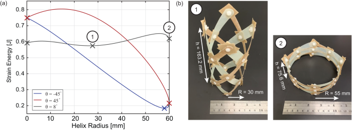
a Variation in stored deformation strain energy as a function of radius and fiber-reinforced composite material properties. b Fabricated antenna in states 1 and 2 and the physical dimensions of the two operating states.
The use of FRP composites for the multi-stable antenna presents a robust implementation for low-infrastructure environments. Multi-stability of FRP composite structures can be maintained over millions of actuation cycles, despite some stiffness reduction of the material under fatigue33. While temperature extremes can shift the location of stable points34, such effects are expected to be minor over the range of temperatures encountered on Earth and can be mitigated through fiber and polymer selection. These small changes in the stable radius have a modest impact on the antenna gain while overall radiation and polarization characteristics remain stable (Supplementary Table 1). Similarly, small vibrations around the stable states will not have a significant impact on electromagnetic performance (Supplementary Table 1). However, dynamic loading (e.g., wind) that causes resonance can inadvertently switch states of the antenna. In fact, dynamic excitation has been proposed as an active actuation strategy for bi-stable structures35. To avoid unintended actuation, the FRP material offers a large design space for tailoring the structural stiffness, and hence resonance frequencies such that they are removed from environmental forcing frequencies. Specifically, we demonstrate that the axial stiffness of the helix can be tuned using the composite fiber angle and strip width while preserving coupling between stable points and antenna reconfiguration (Supplementary Fig. 6). Overall, while state-of-the-art solutions to mechanically reconfigurable antennas trade off mass and portability with environmental robustness (e.g., heavy motor-driven articulated mechanisms36 in contrast to membrane-based origami antennas13), the technology proposed here offers a lightweight, portable structure with robust multi-stability across a large range of environments.
The radio frequency (RF) feeding network
The four conductive strips of the QHA are fed by a dedicated feeding network that is fixed underneath the antenna’s ground plane. The feeding network, shown in Fig. 5, supplies equal amplitude signals with sequential quadrature phases. As shown in Fig. 5a, the feeding network relies on one rat-race coupler and two 3-dB hybrid couplers37 (Supplementary Notes 1, 2).
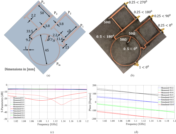
a Proposed feeding network with its dimensions. b Fabricated feeding network with amplitude and phase distribution on each port. c Simulated and measured S-parameters of the feeding network. d The simulated and measured phase difference between different ports.
The rat race coupler is a reciprocal four-port network that splits the input signal Pin into two equal output signals with a phase shift of 180°. Two of the output ports of the rat race coupler connect to two 3-dB hybrid couplers as shown in Fig. 5. Each 3-dB hybrid coupler is also a four-port network that divides its input signal into two equal output signals (P1 and P2 or P3 and P4, respectively) with a 90o phase shift as shown in Fig. 5b. All remaining ports are isolated and connected to 50Ω loads. The combination of a rat-race coupler and the two 3-dB hybrid couplers leads to a quadrature feeding network with equal amplitude signals and sequentially quadrature phases.
Before testing the functionality of the antenna, the feeding network is assessed. The comparison between the simulated and measured S-parameters magnitude of the proposed feeding network is shown in Fig. 5c. Figure 5d presents the simulated and measured phase differences between the various ports of the proposed feeding network. These results prove that the designed network provides equal amplitude signals with sequential quadrature phases.
Ground plane design and sliding feed
The physical realization of the two states of the proposed antenna structure requires sliding the various helical wires along the ground plane as the antenna reconfigures its radius. A customized ground plane is implemented as part of the proposed structure to allow the variation of the antenna’s radius. The typical square ground plane is modified to include four slots coinciding with the motion of the four conductive arms as the antenna changes its radius (Fig. 6a).
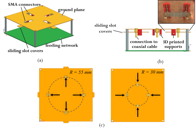
a Isometric view showing a schematic of the ground plane design. b 3D printed support and spring-loaded pins partially assembled with a side view showing a schematic of the ground plane design. c Coaxial feeding movement.
Four coaxial cables with SMA connectors are connected to the four conductive helical arms and move along these slots. The ground of each SMA connector is attached via conductive epoxy to a slot cover that slides underneath the respective slot. A fixed distance is maintained between the cover and the ground plane using 3D-printed supports. To ensure the electrical connectivity between the ground plane and the sliding covers, spring-loaded pins with a gold-plated ball bearing at their tips are integrated with the 3D-printed parts. Figure 6b shows a partially assembled support for the sliding covers. The coaxial feeding movement on the ground plane with the state change of the antenna is shown in Fig. 6c.
Photos of the top and bottom views of the ground plane are shown in Fig. 7a, b. Photos of the completed assembly can be seen in Fig. 7c. The manufactured ground plane is fabricated using 0.5 mm thick Copper and has a side length of 374 mm. A comparison between the performance of the QHA over a full ground plane with its performance over a covered slotted ground is shown in Supplementary Note 3. It is demonstrated that the effect of the slots is negligible.
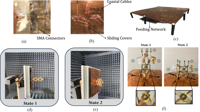
a Top of the ground plane.
b Bottom of the ground plane.
c The full group plane assembly.
d, e Antenna under measurement in the anechoic chamber in states 1 and state 2.
f Illustration of the structure’s transition between state 1 and state 2.
Measured electromagnetic performance of the QHA
The antenna was measured in an anechoic chamber at the Antenna Measurement facility in the EMpact lab at the American University of Beirut. It is a standard ETS Lindgren anechoic chamber38 connected to a Performance Network Analyser (PNA)39, a controller, and a computer to control the turning table and extract the results (Methods). The antenna under test is put in transmitter mode and a horn antenna is used as a receiver.
Figure 7d, e shows the antenna with its own feeding network being tested in an anechoic chamber in its two operating states. The measurement was done in the two stable states of the antenna and the performance was compared to simulation.
The transition of the fabricated antenna from State 1 to State 2 and vice-versa is shown in Fig. 7f, where the fabricated antenna in its two states is presented. Transition from State 1 to State 2 is executed as a result of an applied vertical downward force which, when applied to the tips of the QHA, forces the rotational joints to rotate in the clockwise direction. As a result of this rotation, the conductive strips (brown colored strips in Fig. 7f) rotate in a clockwise and downward direction, the non-conductive strips (white colored strips in Fig. 7f) rotate in a counterclockwise and downwards direction. This increases the radius of the QHA, and transitions it into a stable state 2. On the other hand, a vertical upward force applied to the tips of the QHA in stable state 2, forces the rotational joints to rotate in the counter-clockwise direction. As a result, the conductive strips rotate in a counter-clockwise and upward direction, the non-conductive strips rotate in a clockwise and upward direction, and the radius of the antenna decreases. As a result, the antenna returns to stable state 1.
The comparison between the simulated and measured input reflection coefficients (|S11| [dB]) is presented in Fig. 8a for both states, demonstrating that the antenna preserves the same operational frequency. The great agreement between measured and simulated |S11| demonstrates that the fabricated antenna prototype along its feeding network satisfies the design requirements in terms of frequency operation.
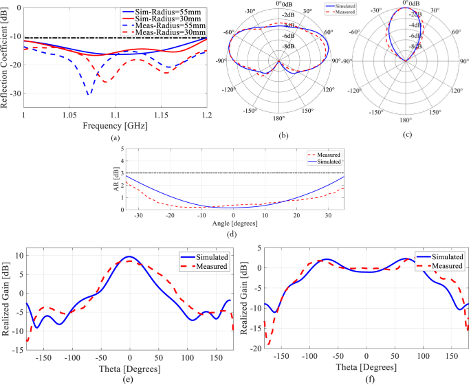
a Reflection coefficient. b The normalized measured and simulated radiation pattern for State 1. c The normalized measured and simulated radiation pattern for State 2. d Measured and simulated Axial Ratio in dB for State 2. e Comparison between measured and simulated realized gain at the operational frequency and for the azimuthal angle (phi = 0) plane cut for variable elevation angle (theta) for state 2 and f state 1.
The radiation characteristics of the fabricated prototype in the two deployed states are similarly assessed and compared to simulations. The radiation patterns of the antenna are measured at f = 1.1 GHz since this is the frequency of interest for the antenna operation. In state 1, the antenna exhibits an almost omnidirectional radiation pattern as shown in Fig. 8b. As for state 2, the antenna exhibits a directional radiation pattern as depicted in Fig. 8c. For both states, the simulated and measured results show good agreement.
The axial ratio of the second state of the proposed antenna structure can be calculated using (3)40.
In state 2, the helix spacing is 0.5λ while its radius is 0.1833λ. These dimensions result in a predicted axial ratio of 0.7546 dB, which is less than the 3 dB threshold. Thus, circularly polarized radiation is obtained in state 2. To validate the circular polarization of the antenna in state 2, the simulated and measured axial ratio at f = 1.1 GHz are plotted in Fig. 8d over the span of elevation angles where the maximum radiation is focused. It is clear that the axial ratio drops to below 3 dB for a range of angles between ± 40° where the maximum radiation is centered, proving that the antenna is circularly polarized.
The antenna exhibits a maximum measured realized gain of 2.6 dB for state 1, while it exhibits a maximum measured realized gain of 8.5 dBic for state 2, which renders state 2 of this antenna suitable for satellite communication. Comparisons between the measured and simulated realized gains for both states of the antenna are shown in Fig. 8e, f. It is clear from Fig. 8 that the measured and simulated results are in excellent agreement, which confirms that the designed antenna achieves its envisioned performance with great fidelity.
Designed QHA Compared to a Conventional QHA
To achieve a normal mode conventional helix, the circumference, C, of the helix, and the spacing, S, between each helical turn, must be less or equal to . As a result, for a frequency of 1.1 GHz, the radius, R, of the helix must be less or equal to 21.7 mm, and the spacing, S, must be less than or equal to 136.0 mm (Supplementary Table 2). On the other hand, to achieve an axial mode conventional helix40, C must be between and in addition to a spacing S of . As a result, for a frequency of 1.1 GHz, axial mode operation is achieved when the radius and spacing of the helix40 are 32.6 mm < R < 58.0 mm, and . The conventional QHA calculation studies the helical spacing between the values of 0 and . However, in our design we went beyond in terms of spacing to venture an approach where we achieve a normal mode and an axial mode corresponding to stable geometries from a mechanical perspective. In other words, an unconventional helical design was selected to merge electromagnetic reconfiguration with mechanical stability.
Hence, a major portion of the analysis executed in this paper is focused on identifying the sweet spot between the mechanical stability of the structure and its electromagnetic performance. To ensure deployment of the QHA while maintaining the same frequency of operation, the radius and spacing must be adjusted to maintain the same strip length. So when the radius of the wire increases, its spacing decreases and vice-versa (as in Eq. (1)).
As can be seen from Supplementary Fig. 5, for a conventional QHA at an operating frequency of 1 GHz the total length of the wire l differs between the normal and axial modes. Therefore, the same conventional antenna cannot operate in two different modes within the same frequency range. Our proposed design overcomes this limitation by preserving the same wire length l for all the radii. This was achieved by modifying the spacing between the wires while taking into consideration the spacing-radius relation (Fig. 2c) ensuring that the mechanical stability of the design is preserved.
We can generalize the design space of reconfigurable electromagnetic performance by representing it as a function of the operating wavelength, λ (Fig. 9a). In this way, the discovered reconfiguration principle can be applied to any desired frequency. As can be seen, for a QHA with 0.5 turns, 0.935λ < S < 1.14 λ, and 0.0833λ < R < 0.133λ, produces an omnidirectional-like pattern. A QHA with 0.5 λ < S < 0.935 λ and 0.133 λ < R < 0.18833 λ is circularly polarized (CP) with a directional pattern. Beyond these limits, the antenna is not resonant (NR). A demonstration of the radiation pattern reconfiguration across a range of operating frequencies is provided in Fig. 9b.
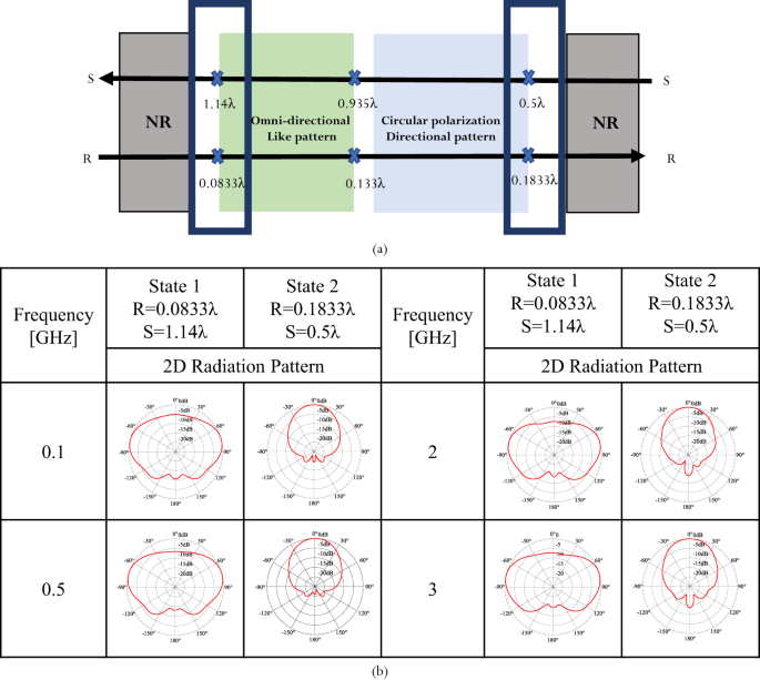
a The design space for antenna performance reconfiguration as a function of geometry. b Radiation pattern reconfiguration across a wide range of operating frequencies.
Comparing passive and active actuation
Multi-stability offers a user-centric approach to antenna actuation that eliminates the need for DC power. This means users can manually adjust the antenna to meet their communication requirements, knowing that multi-stability will precisely configure the structure for optimal electromagnetic performance. This operational principle proves especially advantageous in regions with limited infrastructure and power resources.
Alternatively, a multi-stable antenna can also be autonomously reconfigured via powered actuators. It is noteworthy that in this case, multi-stability still offers significant energy savings as the actuation needs to be powered only to reconfigure the structure while multi-stability maintains the antenna geometry in the desired operational states. In addition, the combination of multi-stability and powered actuation can ensure that the antenna maintains its current state in case of power failure and may be advantageous where safety considerations preclude manual reconfiguration. Stimuli-responsive smart materials are an attractive option for the actuation of multi-stable structures35,41,42 instead of traditional electro-mechanical actuators such as motors. Smart material actuators can interface directly with the structure41 or be embedded in the material35,42 to reduce the mass associated with power transmission (e.g., gears). For the antenna proposed here, shape memory alloys present one actuation possibility, if the antenna is proposed for implementation in different circumstances or environments where power is available and not scarce. These materials exhibit phase transitions43 that allow the actuator to hold a large deformation that can be recovered via resistive heating. A pair of shape memory alloy actuators can be used in an antagonistic arrangement for reversible actuation41,44. We present a proof-of-concept antenna deployment using shape memory alloy spring actuators in Supplementary Fig. 7, however, we emphasize the fact that such actuation is only useful in regions where power resources are available contrary to our intended implementation in this work.
On the other hand, the deployment mechanism adopted for this structure eliminates the need to integrate PIN diodes or any other electronic switch into the feeding network or the antenna itself. Our proposed passive bistable deployment technique offers more robustness, and a greater immunity to environmental factors, and eliminates any nonlinearity effects that may result from the integrated switches. Furthermore, a bias-free system implicates less interference in the antenna’s radiation characteristics, especially in a QHA topology which is an out-of-plane topology. Additionally, it is important to emphasize that realizing the unique reconfigurable functionality of our proposed QHA necessitates a mechanical modification of its structural topology, a feature that cannot be achieved using electronic switching reconfiguration.
No Dish? Try A Portable Weave Helix Antenna | Hackaday
When you think of satellite communications, you probably think of a dish. But that’s not the only option — a new device from the American University of Beruit and Stanford created a portable antenna made of woven materials that packs easily, weighs little, and can reconfigure for ground-to-space or ground-to-ground communications. The antenna reminded us of a finger trap and you can see it for yourself in the video below.
Because of the antenna’s construction, it can fold up and also adjust to different lengths for different purposes. The antenna collapses to a ring that is five inches across and 1 inch tall. The weight? Under two ounces. The actual paper in Nature Communications is available to read online.
Stretched out to about a foot, the antenna is omnidirectional. The size, of course, also changes the resonant frequency. Tuning is no problem, though, since you can easily change the size as needed. The antenna may also find use on satellites where it’s low weight, and compact storage would be a definite advantage.
The antenna’s weave is actually two separate helixes, one conductive and the other insulating. The antenna normally operates in a vertical configuration. It looks like it might be simple to make some version of this without anything exotic. Let us know if you try!
Helical antennas aren’t new, but this is an unusual construction. They are popular as satellite antennas because of their polarization characteristics among other things.
. Other co-authors are from American University of Beirut
.
This work was funded the Swiss State Secretariat for Education, Research, and Innovation.
Related: Maria Sakovsky
, assistant professor of aeronautics and astronautics


No comments:
Post a Comment