Sunday, March 31, 2024

Chinese Carrier Aviation In 2024 - The Year So Far

Chinese Carrier Aviation In 2024 - The Year So Far

navalnews.com

Alex Luck

Chinese efforts modernising and expanding indigenous carrier aviation capabilities have taken several notable development steps over the last few months. The newest aircraft carrier Fujian, currently fitting out in Shanghai, is of course a significant motivating force behind all these programs. The catapult-equipped carrier, a first for China, will possibly undergo her first sea trial within weeks. However, recently observed developments also carry operational implications for PLAN’s current force of two STOBAR (ramp launch) -equipped carriers Liaoning and Shandong. This article aims to provide a brief overview and update regarding relevant recent events.

KJ-600 carrier-borne AEWC aircraft

KJ-600 airframe 7106 in an image circulated on Chinese social media.

The KJ-600 is China’s incoming fixed wing airborne early warning and control (AEWC)-platform. The aircraft is in overall configuration similar to the E-2 Hawkeye-series of aircraft operated by the US Navy. First flight for the type occurred in August 2020. Assuming imagery of flying airframes with serial numbers is reliable, at least six prototypes or pre-production aircraft, numbered 7101 through 7106, exist so far. Furthermore the type in December 2023 has started to appear at China’s land-based catapult testing facility at the Huangdicun naval aviation base. In addition a mockup of the KJ-600 is now also present on the aircraft carrier Fujian, in addition to mockups of fighter jet types J-15 and J-35.

What appears to be KJ-600 airframe 7103 flying overhead in image shared on Chinese social media in late March 2024.

The observation of additional flying prototypes in addition to land-based catapult testing and mock-up testing on Fujian suggests the overall effort is proceeding relatively smoothly. It is unclear at this stage whether China intends to also introduce a cargo-variant of the KJ-600 for carrier onboard delivery (COD)-roles similar to what the USN does with the C-2 Greyhound. Furthermore it is also questionable whether the type will see service off Liaoning and Shandong. Given the STOBAR-carriers respective design-inherent limitations for aircraft launch and stowage, this seems unlikely, but remains to be confirmed.

J-35 new generation carrier-borne fighter

J-35 flying overhead. Image via Sinodefenceforum.com, originally Chinese social media, circulated in early March.

The J-35 represents the next generation of carrier-based fighter capability for PLAN, complementing and eventually replacing the Sukhoi Su-33 derived J-15. The first flight of J-35, itself a heavily revised development of the earlier FC-31 developed by Shenyang Aircraft Corporation (SAC), occurred on October 29, 2021. It remains unclear how many J-35 are flying so far. Two flying prototypes or pre-production airframes appeared in Chinese social media imagery in late March. A mockup of the type started to appear on carrier Fujian in November 2023.

Importantly another mockup also started to appear on carrier Liaoning in February 2024. The first PLAN aircraft carrier, commissioned in 2012, was then just completing her midlife refit (MLU) and has since completed a first post-MLU sea trial. This appearance heavily hints at PLAN intentions to operate this new generation fighter from both the existing STOBAR-carriers and new catapult equipped hulls. Such a step seems logical also in light of PLAN’s requirement to complement and eventually replace its Russian-legacy J-15 across all carriers.

Two J-35 flying overhead in an image circulated in March 2024 on Chinese social media.

Similar to KJ-600 the appearance of more flying airframes in addition to mockup-testing onboard both carriers Fujian and Liaoning supports the notion that the overall J-35 program is progressing well. Whether the second carrier in service, Shandong, will see similar work in the near future remains to be seen. It is also conceivable that the newer carrier is already capable of supporting J-35. Alternatively the ship may undergo modification at a later stage, when her own MLU is due.

J-15 carrier-borne fighter

J-15 fighter tied up in launch position on aircraft carrier Shandong. Image via Chinese social media, originally Chinese state media.

The J-15 represents PLAN’s current carrier-borne fighter capability and is in use on both Liaoning and Shandong. Based on observed numbered airframes seventy or more airframes are in service to supply aircraft for the two STOBAR-carriers and land-based training capacity. Beyond the original STOBAR-fighter variant J-15 has seen further development. This includes a two-seater version for training, the J-15S, but also a variant optimised for electronic warfare dubbed J-15D. In addition a version capable of catapult-launch is in active development and designated J-15B. This model is a continuation of work started with an airframe commonly referred to as J-15T. The original prototype first appeared in land-based testing around 2016.

J-15B landing at land-based PLA training facility. Image via Twitter/X account “@sugar_wsnbn“, originally Chinese state media.

Observable development on J-15D has been prolonged, with the configuration flying first in 2016. It remains unclear, to what degree the type will see introduction across China’s aircraft carrier fleet. At least one airframe continues active testing and the latest imagery of this effort dates from late March. Two mockups of the type have also previously appeared on Liaoning.

An older image showing two J-15D mockups on aircraft carrier Liaoning. Note that the real J-15 is a dual seater. Image via Sinodefenceforum.com.

As for the catapult-launch capable variant J-15B, the most recent imagery again dates to March this year. Pictures circulated on social media show two airframes apparently conducting testing at land-based facilities. The fact that one mockup is present on Fujian suggests that development of the type for operational fielding is proceeding. The relative weighting of the program compared to J-35 and the resulting fleet mix onboard Fujian remains to be seen. It is conceivable that J-15B will become the new standard fighter also replacing older J-15 onboard Liaoning and Shandong. This requirement may arise, once airframes reach the end of useful life or obsolescence due to fitted equipment.

Carrier Fujian approaching first sea trial

Aircraft carrier Fujian fitting out at Jiangnan. Note deck markings being applied and both KJ-600 and J-15 mockup parked between bow catapults. Image via Chinese social media.

In conclusion the recent months have shown lively activity for the development of Chinese carrier aviation. The ongoing testing of all three relevant fixed wing-aviation programs for PLAN suggests healthy progress in fielding an expanded and more modern carrier aircraft-capability. The most important next step in this regard is indubitably the first sea trial for carrier Fujian. The third Chinese carrier, and the first equipped with catapults for aircraft-launch, has earlier this year returned to her fitting out-berth, after completing some cleanup work in drydock. Most recently the ship has seen her life-rafts fitted and application of flightdeck markings is also currently underway. As such a first sea trial within weeks appears plausible now.


Will China’s fourth aircraft carrier steer towards troubled waters in Asia and challenge the US Navy?

scmp.com

China’s fourth aircraft carrier is expected to help expand its maritime presence in Asia, but a lack of naval combat experience and insufficient supply bases in the region could hamper its power projection.

While the mainland Chinese military’s focus for its aircraft carrier deployment is likely Taiwan, it could also engage in sabre-rattling measures in the South China Sea, security analysts say.

During a legislative session in Beijing earlier this month, Yuan Huazhi, the political commissar of the Chinese People’s Liberation Army (PLA) Navy, said China would unveil its fourth aircraft carrier soon.

China’s third aircraft carrier, the Fujian, is seen under construction in Shanghai’s Jiangnan shipyard in 2019. Photo: Weibo

When asked in an interview if the latest carrier is going to be nuclear-powered, Yuan said details of the vessel would be announced “soon”, according to a video posted by the Hong Kong Commercial Daily on the social media platform Weibo.

There had been no delays or bottlenecks in the construction of the new carrier, Yuan said. His comments were the first confirmation of China’s efforts to build its fourth aircraft carrier, commonly known as the Type 004.

Illustrations of the vessel have been circulating online, with the artwork purportedly coming from the Jiangnan shipyard in Shanghai, where it is believed to be under construction.

Chinese scientists send aircraft carrier catapult technology soaring

25 Mar 2024
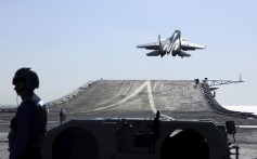
Abdul Rahman Yaacob, a research fellow in the Southeast Asia programme at Australia’s Lowy Institute, said if the fourth aircraft carrier is fuelled by nuclear power, it could operate “power-hungry” weapon systems and equipment.

“A nuclear-powered aircraft carrier can operate longer at sea without replenishment, thus the Chinese Navy can project and exert a stronger presence,” he added.

An aircraft carrier typically operates with an escort of submarines, destroyers, and supply ships and would require replenishment and refuelling. China does not have access to many military or supply bases in the region, unlike the US, Rahman says.

A weekly curated round-up of social, political and economic stories from China and how they impact the world.

By submitting, you consent to receiving marketing emails from SCMP. If you don't want these, tick here

While the US Navy is experienced in naval battles, the Chinese navy has not been tested as yet, and it remains to be seen if its aircraft carrier group can perform in wartime conditions as effectively as the Americans, Rahman said.
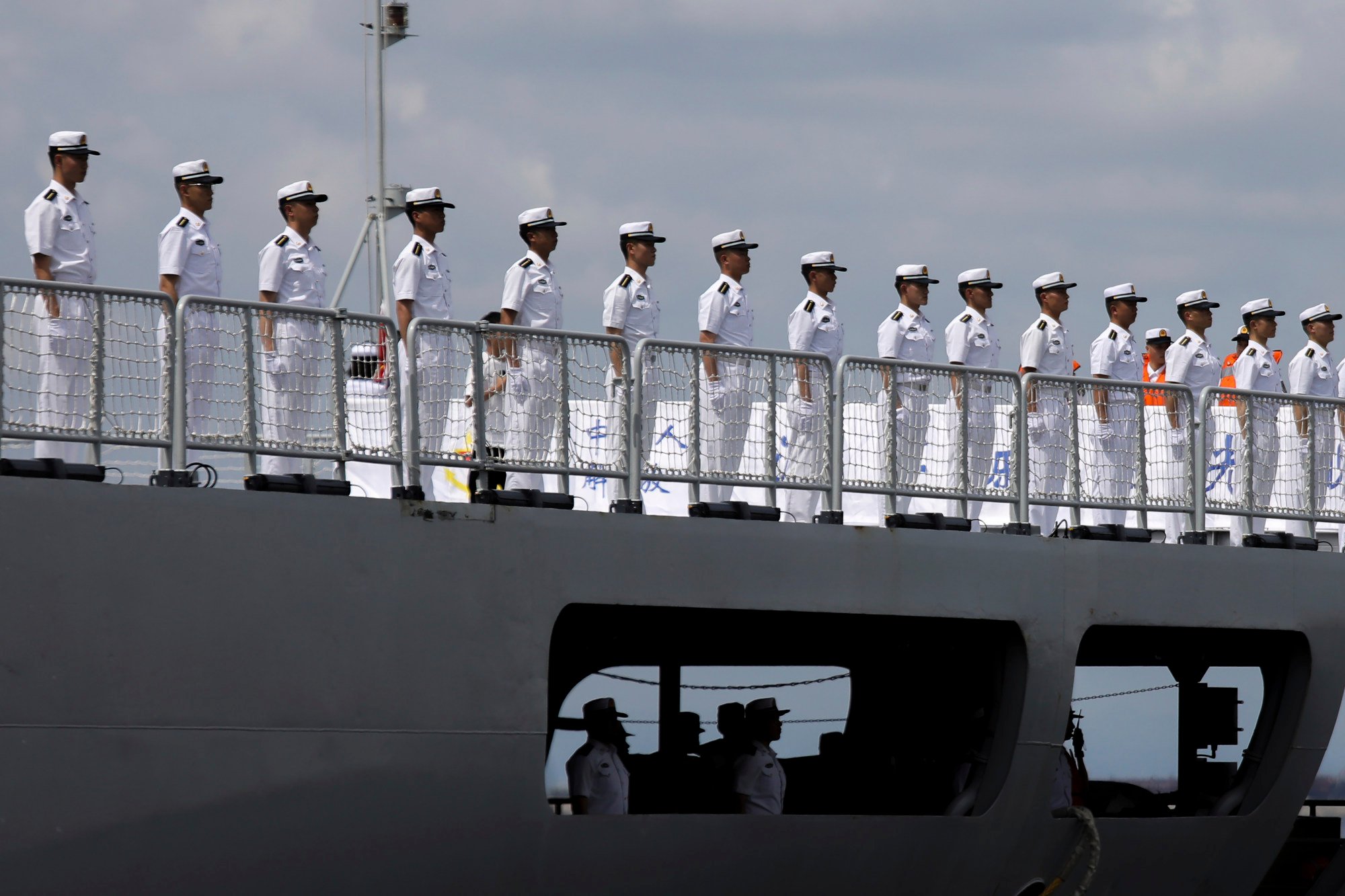
Chinese sailors from the PLA Navy stand in formation on board a naval training ship last summer. Photo: AP

Apart from its regional supply bases, the US can also tap support from its allies including Australia, South Korea, and Japan, enabling it to have an edge over the Chinese, he added.

Malcolm Davis, a senior analyst at the Australian Strategic Policy Institute think tank, said that the regional balance of power is expected to be recalibrated as China boosts its aircraft-carrier capabilities and catches up with the US.

“But operational context matters”, Davis said, noting that the Chinese carriers’ primary mission is to support the PLA’s joint landing operations targeting Taiwan.

“So while the carriers will allow the PLA Navy to operate with more confidence in other regional contingencies, I think its key role is still Taiwan-focused,” Davis said.

Amid Taiwan tensions, Beijing reveals it is building aircraft carrier No 4

6 Mar 2024

China’s third aircraft carrier, the Fujian, is equipped with advanced features including electromagnetic catapults and arresting devices that allow warplanes to be launched more frequently. Its two other operational aircraft carriers are the Liaoning and the Shandong.

The unnamed fourth carrier is likely to be nuclear-powered and comparable in size and capability to the US Nimitz-class aircraft carriers, Davis said.

The 10 Nimitz-class nuclear-powered aircraft carriers are capable of operating for over 20 years without refuelling and have a potential service life of over 50 years. In total, the US Navy has 11 aircraft carriers.

Given the global responsibilities of the US, it cannot concentrate its aircraft carriers in one region, Davis said.
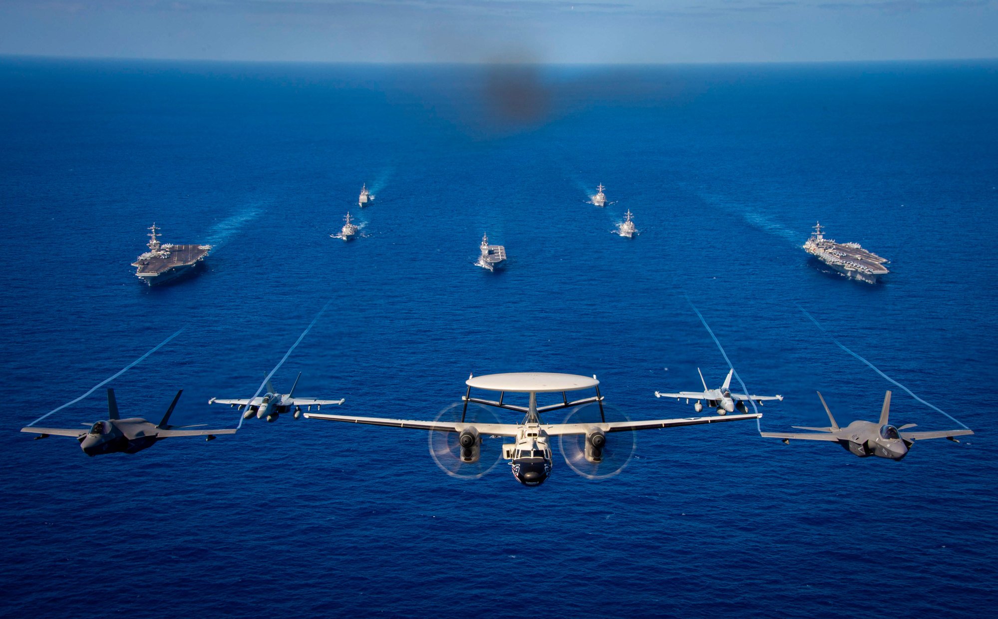
Two Nimitz-class aircraft carriers of the US Navy sail in formation with guided-missile cruiser and destroyers during an exercise in January. Photo: US Navy/Handout

“China can concentrate its carrier capabilities while seeking to project power beyond the second island chain”, Davis said, adding: “It opens the path for future carrier development for China’s navy as it builds up a multi-carrier force and gains experience in naval air operations.”

The first island chain refers to the Kuril Islands, the main Japanese archipelago, Okinawa, the northern part of the Philippine archipelago, the Malaysian peninsula, and Taiwan while the second spans from some Japanese islands to Guam and Micronesia.

Joshua Bernard Espeña, vice-president at the International Development and Security Cooperation think tank in Manila, said China’s fourth aircraft carrier would lead to “more sabre-rattling” by Beijing and have an impact on Southeast Asia.

China could seek to deter countries whom it perceives as being responsible for escalating tensions in the South China Sea and the Taiwan Strait, Espeña said. As such, regional countries like the Philippines must learn to deter China from taking provocative steps, he added.

A Philippine resupply vessel is blasted with water cannons by a Chinese coastguard ship near Second Thomas Shoal, in the disputed South China Sea, on March 23. Photo: Armed Forces of the Philippines via AP

China and the Philippines have been locked in clashes in the South China Sea for months, with the Chinese Navy having deployed its coastguard ships and other non-military vessels to try to force Philippine boats out of the contested waters.

“Regional defence planners must develop approaches to counter [China’s] strengths and exploit weaknesses of the carrier task force,” Espeña said. One drawback faced by the Chinese task force is that some of its aircraft carriers based on Soviet-era designs had encountered “maintenance issues”, according to Espeña.

China’s naval ambitions

China has been embarking on efforts to modernise its navy following disruptions caused by the pandemic. In addition to its aircraft carriers, China has launched guided-missile destroyers and amphibious assault ships in the past few years, with the capacity to operate thousands of miles away from its coastal areas.

In a testimony to the US Armed Services House Committee last week, US Navy Admiral John Aquilino said China’s military is expanding at a rate not seen since World War II. The head of the US Indo-Pacific Command said mainland China is on track to meet its goal of invading Taiwan by 2027.

Chinese security analysts cited by the state-run tabloid The Global Times said China is expected to build more aircraft carriers as part of its strategy to build a blue-water navy capable of projecting its power near and far from its waters. These carriers can better safeguard China’s sovereignty and territorial integrity, the analysts said.

Once China has achieved the capacity to build a navy that can gain control of the seas around the first island chain and deny access to the second, it will seek to project its power further afield, including in the Indian Ocean, Davis said.
03:03

Taiwan simulates attack from mainland China as island’s military conscripts begin extended service

Taiwan simulates attack from mainland China as island’s military conscripts begin extended service

“So when you look at Chinese naval power and consider whether it can challenge US interests, I would argue it certainly does, as part of a broader suite of military capabilities across the PLA including long-range air power, long-range precision missiles, space and cyber capabilities,” Davis said.

“Sea power is a key component of China’s growing military power, and the concern in the West is that Beijing will use military force to achieve policy objectives at the expense of a free and open Indo-Pacific region.”

In the face of China’s expanding navy capabilities, smaller Southeast Asian countries could learn lessons from the war in Ukraine and develop effective countermeasures, Rahman said.

China has drawn its line in the Gulf of Tonkin. Is the South China Sea next?

19 Mar 2024
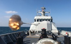
Ukraine’s sea drones have reportedly been thwarting Russian vessels recently, including a patrol ship that was sunk in the Black Sea earlier this month in one such attack.

Citing these attacks as an example, Rahman said: “The use of drones, mobile anti-ship missiles and sea mines – these are cheaper systems that Indo-Pacific countries could deploy to counter the Chinese Navy and its aircraft carriers.”

 

U.S. Army Moves Closer to Unleashing ‘Dark Eagle’ Long-Range Hypersonic Weapon in Major Test with U.S. Navy - The Debrief


 US Army Deploys First Long-Range Hypersonic Weapon System 

 The US Army has successfully fielded its first long-range hypersonic weapon (LRHW) system, marking a significant milestone in its expeditionary hypersonic launch capabilities. The LRHW system, consisting of a prototype ballistic missile with a Common Hypersonic Glide Body (C-HGB), was deployed by the 1st Multi-Domain Task Force (1st MDTF) long-range fires battalion, 5th Battalion and 3rd Field Artillery Regiment (5-3 LRFB) during the exercise Thunderbolt Strike. 

This event represents a successful collaboration between the 1st MDTF, RCCTO, industry, and Army partners, generating immediate feedback on the complex system's integration. Hypersonic weapons, like the LRHW, are significant because they can reach speeds of Mach 5 or higher, making them extremely difficult to intercept by modern air defense systems. 

The US Army plans to field a prototype LRHW battery in FY2023, followed by the transition into a formal Program of Record and the implementation of the second and third batteries in FY2025 and FY2027. The LRHW's deployment is a positive development for the US military, which has been lagging in hypersonic weapon technology. The successful deployment could help bridge the gap in the ongoing competition for hypersonic weapons dominance.

 U.S. Army Moves Closer to Unleashing ‘Dark Eagle’ Long-Range Hypersonic Weapon in Major Test with U.S. Navy - The Debrief

The U.S. military is getting closer to deploying a new, extremely fast and highly maneuverable long-range missile called the

Long-Range Hypersonic Weapon (LRHW). The Navy and Army are working together to test this missile system.

The Navy will first test launching a component based on a Sandia Laboratories vehicle called the Common Hypersonic Glide Body (C-HGB) using their rocket booster. Once launched, the C-HGB can glide at speeds over 5 times the speed of sound, making it very difficult to shoot down.

The Army's version is nicknamed "Dark Eagle." After the Navy's test, the Army plans to test firing the Dark Eagle missile from a truck-based launch system later this year. When operational, Dark Eagle missiles will be able to hit targets up to 1,725 miles away while traveling at over 3,800 mph.

This new hypersonic weapon is seen as crucial for the U.S. to counter similar ultra-high-speed missile projects being developed by Russia and China. The first Dark Eagle missiles will be deployed at Joint Base Lewis-McChord once testing is complete.

Joint Testing of a Long-Range Hypersonic Weapon

The article discusses the upcoming joint testing of a long-range hypersonic weapon by the U.S. Army and U.S. Navy. The key points are:

  1. The U.S. Navy is preparing to test the Common Hypersonic Glide Body (C-HGB), which is part of the Long-Range Hypersonic Weapon (LRHW) program being developed with the U.S. Army.
  2. The C-HGB is designed to be launched by the Navy's booster rocket and can glide at speeds of Mach 5 or greater, making it highly maneuverable and difficult to intercept.
  3. The Army's version of the LRHW is called "Dark Eagle," capable of reaching targets within 1,725 miles at speeds exceeding 3,800 miles per hour.
  4. After the Navy's initial C-HGB test this spring, the Army plans to conduct its own test later this summer from a ground-based truck-launched system developed by Lockheed Martin.
  5. The first LRHW battery will be operated by the 5th Battalion, 3rd Field Artillery Regiment at Joint Base Lewis-McChord, with additional batteries planned for the 1st Multi Domain Task Force.
  6. The U.S. is racing against similar hypersonic weapon developments by Russia and China, and the successful testing of these weapons is seen as a strategic priority for the military.

Long-Range Hypersonic Weapon (LRHW) program

Here are some more details about the Long-Range Hypersonic Weapon (LRHW) program, the contractors involved, and its expected performance:

Contractors:

  • Dynetics, a subsidiary of Leidos, was contracted to develop the prototypes of the Common Hypersonic Glide Body (C-HGB) that is the core component of the LRHW. This marks the first time a private U.S. company has built hypersonic weapons.
  • Lockheed Martin is performing the weapon system integration for the Army's ground-based truck-launched LRHW systems.

Expected Performance:

  • The Army's version, nicknamed "Dark Eagle", is expected to have a range of 1,725 miles (2,775 km).
  • It will be capable of traveling at speeds exceeding 3,800 mph (6,115 kph), which is over 5 times the speed of sound.
  • It climbs to a high atmospheric altitude where it can glide and maneuver, making it very difficult to track and intercept.
  • This high speed and maneuverability allows it to penetrate advanced anti-air defenses.
  • It is designed to precisely strike "high-value, time-critical" targets.

Other Details:

  • The C-HGB is boosted to hypersonic speeds by the Navy's 34.5-inch rocket booster.
  • The Army is organizing LRHW batteries, each with 4 truck-mounted Transporter Erector Launcher systems fitted on M870A4 trailers.
  • The first LRHW battery will be based at Joint Base Lewis-McChord under the 5th Battalion, 3rd Field Artillery Regiment.
  • Additional batteries will follow for the 1st Multi Domain Task Force as more systems come online.

So in summary, this advanced hypersonic glide vehicle leverages technology from multiple contractors to provide an extremely fast, maneuverable and long-range precision strike capability for the U.S. military.


Saturday, March 30, 2024

OSINT Complete Guide for Beginners | OSINT


OSINT Complete Guide for Beginners | OSINT

Access a meticulously curated OSINT cheatsheet featuring a categorized compilation of top resources for Open Source Intelligence (OSINT). Elevate your investigative skills with powerful tools.

Welcome to Our Comprehensive OSINT Cheatsheet: Your Ultimate Resource for Open Source Intelligence

Are you ready to take your Open Source Intelligence (OSINT) skills to the next level? Look no further! Our meticulously curated OSINT cheatsheet brings you an extensive array of resources, expertly categorized for your convenience. Whether you're a seasoned investigator, cybersecurity enthusiast, or curious learner, this comprehensive guide will empower you to harness the power of OSINT to its fullest potential.

Fuel your OSINT journey with our carefully curated cheatsheet, offering a wealth of resources in each category. Uncover hidden patterns, unearth critical insights, and stay at the forefront of intelligence gathering. No matter your level of expertise, our OSINT cheat sheet is your compass in navigating the vast landscape of open-source intelligence.

Unlock the potential of OSINT today! Explore our comprehensive cheatsheet and watch your investigative skills soar. Remember, knowledge is power, and with our OSINT resources, you're one step closer to becoming an intelligence-gathering virtuoso.

Don't miss out on the opportunity to revolutionize your OSINT game. Dive into our curated resources and elevate your investigative prowess. Explore the cheatsheet now!


Friday, March 29, 2024

Waveform Design for Joint Communication and SAR Imaging Under Random Signaling

Refer to caption
Monostatic JCASAR geometry.

Summary

This paper proposes a novel joint communication and synthetic aperture radar (SAR) imaging system called JCASAR based on orthogonal frequency-division multiplexing (OFDM) signaling with cyclic prefix. The key contributions are:

  1. It introduces an OFDM-based signal model for joint SAR imaging and communication, where a least squares estimator is proposed for range profiling instead of traditional matched filters.
  2. It investigates the optimal waveform design for SAR imaging and JCASAR under random (Gaussian distributed) signaling by minimizing the mean squared error of the range profile estimator.
  3. It conceives power allocation strategies that achieve a flexible trade-off between SAR imaging and communication performance for the JCASAR system.
  4. Numerical simulations validate the effectiveness of the proposed random waveform design and demonstrate the sensing-communication performance trade-off.

The main novelty lies in utilizing random OFDM signals that can simultaneously reconstruct the target profile for SAR imaging while conveying communication information, which enables integrated sensing and communication for future 6G systems. The waveform optimization provides a means to balance the sensing and communication requirements.

OFDM as used in JCASAR

In the proposed JCASAR system, orthogonal frequency-division multiplexing (OFDM) signaling with cyclic prefix (CP) is employed to enable joint communication and SAR imaging capabilities.

OFDM is a multicarrier modulation technique where the available bandwidth is divided into multiple orthogonal subcarriers. Data symbols are modulated onto these subcarriers in the frequency domain using an inverse fast Fourier transform (IFFT).

The key aspects of using OFDM with CP for JCASAR are:

  1. Multicarrier modulation: The JCASAR signal consists of N orthogonal subcarriers, where information symbols are modulated onto each subcarrier.
  2. Cyclic prefix: A cyclic prefix is added by copying the last part of the OFDM symbol and appending it to the start. This converts the linear convolution with the channel into circular convolution, avoiding inter-symbol interference.
  3. Random signaling: Unlike conventional SAR which uses deterministic waveforms, in JCASAR the symbols modulated on each subcarrier follow a complex Gaussian distribution to enable communication.

The discrete-time baseband OFDM signal with CP can be represented as:

s(t) = (1/N) Σ Sk exp(j2πkΔft), t ∈ [0, T + TCP]

Where Sk are the modulated symbols, Δf is the subcarrier spacing, T is the OFDM symbol duration, and TCP is the CP duration.

  1. SAR range profiling: At the receiver, the CP allows separating the received signal into different range cells corresponding to different delay taps. This enables reconstructing the range profile using a least squares estimator instead of matched filtering.

So in summary, OFDM with CP enables converting the SAR channel into multiple parallel sub-channels, allowing joint design of sensing (range profile estimation) and communication (Gaussian modulated subcarriers) waveforms in JCASAR.

power and bandwidth split

The paper does not explicitly discuss how the total power and bandwidth are split between the SAR imaging and communications functionalities in the proposed JCASAR system. However, some insights can be gained from the waveform design formulation:

  1. The total available bandwidth B is utilized for the multicarrier OFDM signal with N subcarriers, where B = N*Δf and Δf is the subcarrier spacing.
  2. All N subcarriers carry the same OFDM signal waveform, which is used for both SAR imaging and communication.
  3. The power allocation across the N subcarriers is the key factor that enables trading off SAR imaging and communication performance.

Specifically, the paper formulates an optimization problem to minimize the mean squared error (MSE) of the SAR range profile estimation, subject to a constraint on the achievable communication rate over the subcarriers.

The decision variables are the power allocation coefficients {P0, P1, ..., PN-1} across subcarriers, subject to a total power constraint ΣPi = P.

  1. The communication rate constraint log(det(I + ΛP*H)) ≥ R0 ensures that the subcarrier power allocation ΛP can support a minimum rate R0 over the channel H.
  2. Different power allocation strategies trade-off SAR imaging MSE and communication rate R0, providing a flexible performance tradeoff.

So in essence, the total bandwidth B is fully utilized by the N-subcarrier OFDM signal, but the power is dynamically allocated across subcarriers based on the desired emphasis on SAR imaging versus communication performance. However, the split of total transmit power between the two functionalities is not explicitly specified.

Authors, associations, previous work

The paper is authored by Bowen Zheng and Fan Liu, who are affiliated with the School of System Design and Intelligent Manufacturing (SDIM) at the Southern University of Science and Technology in Shenzhen, China.

Fan Liu (liuf6@sustech.edu.cn) received his Ph.D. degree from Beijing Institute of Technology, China, in 2018. He is now an assistant professor at the Southern University of Science and Technology, Shenzhen 518055, China. He serves as the founding academic chair of the IEEE Communications Society (ComSoc) Integrated Sensing and Communications (ISAC) Emerging Technology Initiative, an associate editor of IEEE Communications Letters and IEEE Open Journal of Signal Processing, and a founding member of the IEEE Signal Processing Society (SPS) ISAC Technical Working Group. He is a recipient of the 2023 ComSoc Stephan O. Rice Prize, 2023 IEEE ICC Best Paper Award, 2021 SPS Young Author Best Paper Award, and 2019 Chinese Institute of Electronics Best Doctoral Thesis Award. His research interests include signal processing, wireless communications, and, in particular, ISAC. He is a Member of IEEE.

His recent published work not referenced in the paper seems particularly relevant.
 
F. Liu et al., "Seventy Years of Radar and Communications: The road from separation to integration," in IEEE Signal Processing Magazine, vol. 40, no. 5, pp. 106-121, July 2023, doi: 10.1109/MSP.2023.3272881.

Abstract: Radar and communications (R&C) as key utilities of electromagnetic (EM) waves have fundamentally shaped human society and triggered the modern information age. Although R&C had been historically progressing separately, in recent decades, they have been converging toward integration, forming integrated sensing and communication (ISAC) systems, giving rise to new highly desirable capabilities in next-generation wireless networks and future radars. 

To better understand the essence of ISAC, this article provides a systematic overview of the historical development of R&C from a signal processing (SP) perspective. We first interpret the duality between R&C as signals and systems, followed by an introduction of their fundamental principles. We then elaborate on the two main trends in their technological evolution, namely, the increase of frequencies and bandwidths and the expansion of antenna arrays. We then show how the intertwined narratives of R&C evolved into ISAC and discuss the resultant SP framework. Finally, we overview future research directions in this field.

keywords: {Systematics;Wireless networks;Radar;Bandwidth;Market research;Radar antennas;Electromagnetic scattering},

URL: https://ieeexplore.ieee.org/stamp/stamp.jsp?tp=&arnumber=10188491&isnumber=10188464 

data, language, or models used, or resulting artifacts

The paper does not explicitly mention using any pre-existing data, language models, or other artifacts as inputs to the research. However, it does describe generating some artifacts as a result of the proposed methodology:

  1. Simulated SAR Imaging Results: The authors provide simulated SAR imaging results for both point targets and extended targets (like a car model) using the proposed JCASAR system with different waveform designs:
    • Gaussian random signal with uniform power allocation
    • Gaussian random signal with communication-optimal power allocation
    • Constant modulus signal (for comparison)

These simulated SAR images visualize the impact of the random ISAC waveforms on imaging performance compared to conventional constant modulus signals.

  1. Performance Metric Plots: The paper includes plots of two key performance metrics: a) Normalized mean squared error (MSE) of the range profile estimation for different waveform designs across varying SNRs (Fig. 4) b) Trade-off curve between MSE of SAR imaging and achievable communication rate under different SNRs (Fig. 5)

These plots quantify the sensing-communication performance tradeoff enabled by the proposed power allocation optimization for the JCASAR waveforms.

While no external data sources are mentioned, the results, analysis, and visualizations in the paper can be considered artifacts generated by implementing the proposed JCASAR signal model, waveform optimization, and simulation methodology described in the work.


Waveform Design for Joint Communication and SAR Imaging Under Random Signaling

Electrical Engineering and Systems Science > Signal Processing

Abstract

Conventional synthetic aperture radar (SAR) imaging systems typically employ deterministic signal designs, which lack the capability to convey communication information and are thus not suitable for integrated sensing and communication (ISAC) scenarios.

In this letter, we propose a joint communication and SAR imaging (JCASAR) system based on orthogonal frequency-division multiplexing (OFDM) signal with cyclic prefix (CP), which is capable of reconstructing the target profile while serving a communication user. In contrast to traditional matched filters, we propose a least squares (LS) estimator for range profiling.

Then the SAR image is obtained followed by range cell migration correction (RCMC) and azimuth processing. By minimizing the mean squared error (MSE) of the proposed LS estimator, we investigate the optimal waveform design for SAR imaging, and JCASAR under random signaling, where power allocation strategies are conceived for Gaussian-distributed ISAC signals, in an effort to strike a flexible performance tradeoff between the communication and SAR imaging tasks.

Numerical results are provided to validate the effectiveness of the proposed ISAC waveform design for JCASAR systems.
Comments: 5 pages
Subjects: Signal Processing (eess.SP)
Cite as: arXiv:2403.17627 [eess.SP]
  (or arXiv:2403.17627v1 [eess.SP] for this version)
  https://doi.org/10.48550/arXiv.2403.17627

Submission history

From: Bowen Zheng [view email]
[v1] Tue, 26 Mar 2024 12:04:09 UTC (2,524 KB)

License: arXiv.org perpetual non-exclusive license
arXiv:2403.17627v1 [eess.SP] 26 Mar 2024

Waveform Design for Joint Communication and SAR Imaging Under Random Signaling

Bowen Zheng and Fan Liu This work was supported in part by Special Funds for the Cultivation of Guangdong College Students’ Scientific and Technological Innovation (“Climbing Program” Special Funds, No. pdjh2024c11603), in part by National Natural Science Foundation of China (NSFC) Project No. 62101234. (Corresponding author: Fan Liu.) Bowen Zheng and Fan Liu are with the School of System Design and Intelligent Manufacturing (SDIM), Southern University of Science and Technology, Shenzhen 518055, China (e-mail: zhengbw2022@mail.sustech.edu.cn; liuf6@sustech.edu.cn).
Abstract

Conventional synthetic aperture radar (SAR) imaging systems typically employ deterministic signal designs, which lack the capability to convey communication information and are thus not suitable for integrated sensing and communication (ISAC) scenarios. In this letter, we propose a joint communication and SAR imaging (JCASAR) system based on orthogonal frequency-division multiplexing (OFDM) signal with cyclic prefix (CP), which is capable of reconstructing the target profile while serving a communication user. In contrast to traditional matched filters, we propose a least squares (LS) estimator for range profiling. Then the SAR image is obtained followed by range cell migration correction (RCMC) and azimuth processing. By minimizing the mean squared error (MSE) of the proposed LS estimator, we investigate the optimal waveform design for SAR imaging, and JCASAR under random signaling, where power allocation strategies are conceived for Gaussian-distributed ISAC signals, in an effort to strike a flexible performance tradeoff between the communication and SAR imaging tasks. Numerical results are provided to validate the effectiveness of the proposed ISAC waveform design for JCASAR systems.

Index Terms:
Integrated sensing and communication (ISAC), synthetic aperture radar (SAR) imaging, orthogonal frequency-division multiplexing (OFDM), Gaussian signaling.

I Introduction

Recently, the ITU-R has endorsed the draft recommendation for IMT-2030 (6G), incorporating ISAC as one of the six primary application scenarios within the 6G framework [1]. The fundamental vision of ISAC is to involve the pervasive deployment of wireless sensing capabilities across the 6G network [2],[3]. This vision is anticipated to serve as a crucial facilitator for many use cases [4], among which RF imaging is indispensable, thanks to its ability to generate high-resolution images under diverse conditions, offering all-weather and day-and-night imaging capabilities. By equipping the 6G network with the RF imaging functionality, it may play a critical role in numerous emerging scenarios requiring simultaneous communication and imaging services, such as low-altitude space economy applications, where the UAVs perform environmental monitoring while communicating with users.

The RF imaging systems deployed on UAV platforms typically operate in the SAR mode [5]. Conventional SAR imaging employs linear frequency modulation or step frequency waveforms. However, in high-bandwidth radar systems, these signals encounter Inter-Range Cell Interference (IRCI), which arises from the presence of numerous range cells within a range line, where sidelobes induced by matched filters disrupt adjacent range cells. Inspired by the orthogonal frequency-division multiplexing (OFDM) technique, a pivotal technology in WiFi (IEEE 802.11), LTE and 5G, OFDM SAR systems have received significant attention in recent years. The investigation into range ambiguity in OFDM SAR was explored in [6], while [7] delved into cross-range reconstruction. Notably, these studies employed imaging algorithms akin to conventional SAR systems. Drawing inspiration from wireless communication applications where an OFDM signal with sufficient cyclic prefix can transform an Inter-Symbol Interference (ISI) channel into multiple ISI-free subchannels, a pioneering algorithm for SAR imaging with CP-OFDM signal was introduced in [8]. Another innovative work, by reformulating the system to a linear model, contributed to improving the performance of the SAR imaging system [9]. Moreover, investigations into SAR imaging algorithms involving MIMO-OFDM systems and waveform design were conducted in [10] and [11]. However, the OFDM SAR imaging system waveforms proposed in [6]-[11] are solely designed for SAR imaging and lack the capability to convey useful information, making them unsuitable in ISAC scenarios.

Recently, there have been noteworthy studies focusing on joint communication and SAR imaging. In [12], a waveform design approach based on time-frequency spectrum shaping is proposed to achieve JCASAR. Furthermore, [13] introduces a comprehensive watermarking framework for JCASAR system. These works generally employ orthogonal resource allocation for achieving JCASAR, where the communication and sensing waveforms are separated over frequency or time domains. However, they are generally unable to optimize the resource utilization to its fullest potential compared to fully unified waveform design [4]. To realize JCASAR through the latter technique, two primary challenges emerge. Firstly, the signal should possess randomness to effectively convey information, which may degrade the SAR imaging performance. Secondly, the signal should be able to achive a favorable performance tradeoff between imaging and communication. These challenges motivate the study of this letter.

To tackle the above challenges, this letter proposes a novel waveform design approach for JCASAR system by taking into account the data randomness. We begin by introducing the system model and corresponding performance metric. Subsequently, by imposing the MSE of the LS estimator as an objective function, while ensuring the communication achievable rate, we propose an optimal power allocation strategy that achieves a scalable performance tradeoff between imaging and communications. Finally, we verify our analysis through numerical simulation results.

Refer to caption
Figure 1: Monostatic JCASAR geometry.

II System Model

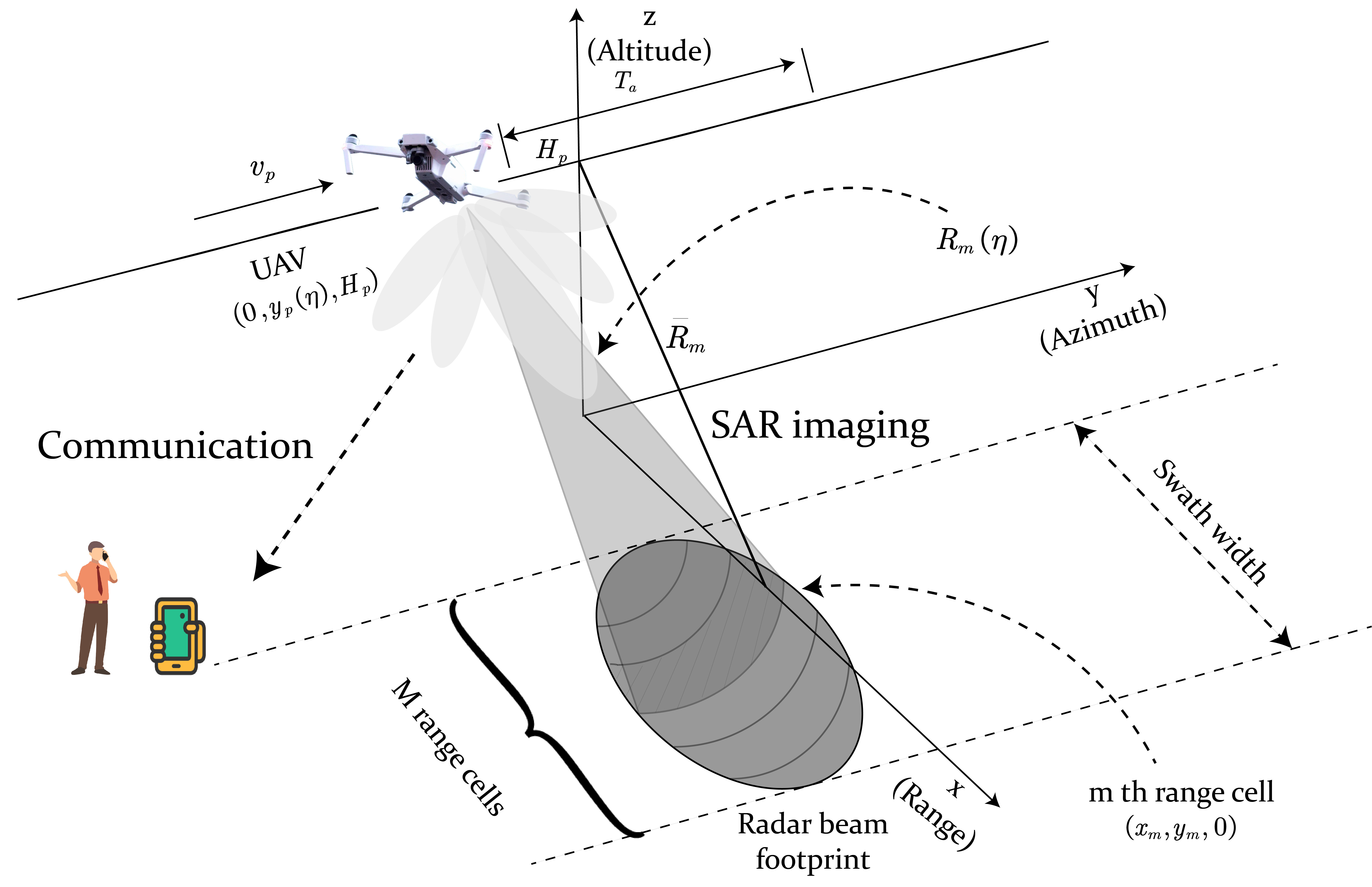
We consider a UAV for low-altitude space economy applications, which is reconstructing the profile of the target or environment and transmitting the imaging information to the user for navigation or path planning purposes, as illustrated in Fig. 1. We assume that the ISAC signal emitted by UAV is unknown to the communication user but is perfectly known at UAV for imaging application. Subsequently, the next two subsections will provide details of the communication model and the SAR imaging model.

II-A OFDM Communication Model

Consider an OFDM signal with N subcarriers, with the subcarrier spacing, bandwidth, and OFDM symbol duration being given as Δf, B=NΔf, and T=1/Δf. Let Sk represents the symbol modulated on the k-th subcarrier, and k=0N1𝔼[|Sk|2]=N.

The discrete-time OFDM signal can be represented as the inverse fast Fourier transform (IFFT) of the vector


s(t)=1Nk=0N1Skexp{j2πkΔft},t[0,T+TCP],
(1)

the symbol TCP represent the time duration of the cyclic prefix, which aims to transform an Inter-Symbol Interference (ISI) channel into multiple ISI-free subchannels.

In this scenario, the channel between UAV and the communication user mainly depends on pass loss effect (i.e. PL=10log10Glλ2(4πd)2 (dB), where Gl is the product of the transmit and receive antenna gains), which is up to the distance between UAV and the communication user. Due to the fact that the UAV may be trated as quasi-static during a short time slot (say, e.g., 1ms), we assume the channel remains constant within an OFDM symbol. In this letter, we explore Gaussian signaling for the JCASAR system, which achieves the capacity of point-to-point Gaussian channels [14], with the achievable rate expressed as


C=Bi=0N1log(1+Pi|hi|2σn2).
(2)

II-B OFDM SAR Imaging Model

Consider the JCASAR geometry shown in Fig. 1. The UAV is moving parallelly to the y-axis and the instantaneous position of UAV can be expressed as (0,yp(η),Hp), where η denotes the slow time index in SAR imaging and Hp is the altitude of the UAV. Given the bandwidth B, the range resolution of the system is ρr=c/2B. Specifically, we assume that there are M range cells in the swath width. According to [8], in order to achieve IRIC-free SAR imaging, the CP length should be at least M1, resulting in TCP=(M1)/B.

The received signal from the m-th range cell can be expressed as


um(t,η) =gmεa(η)exp{j4πfcRm(η)c}
(3)


×1Nk=0N1Skexp{j2πkT[t2Rm(η)c]}


+w(t,η),t[2Rm(η)c,2Rm(η)c+T+TCP],

where Rm(η)=R¯m2+vp2η2, R¯m is the slant range when the UAV is closest to the center of the target, gm is the radar cross section (RCS) coefficient caused by the scatters in the m-th range cell, εa(η) is the azimuth envelope, and w denotes the noise. The complex envelope of the received signal from all the range cells can be written as


y(t,η)=mum(t,η),
(4)

At the receiver, the baseband signal is sampled with sampling interval Ts=1/B, in which case t2Rm(η)/c may be written as


t2Rm(η)c=t2(Rn(η)+mρr)c=tt0(η)mTs,
(5)

Let the sampling start at the moment when the received pulse begins, after a delay of t0(η) for the first arriving version of the transmitted pulse, combing (3) - (5), for a fixed slow time index, the received sequence may be recast as


y[i]=m=0M1dms[im]+w[i],i=0,1N+2M3,
(6)

where dm=gmεa(η)exp{j4πfcRm(η)c} is the weighting RCS coefficient to be estimated, which contains the phase history within synthetic aperture time, i denotes the fast time index, and s[im] denotes the transmitted signal sampled at (im)Ts in (1) (i.e. s[im]=s((im)Ts)). In this JCASAR system, we consider a special case called swath width matched pulse (SWMP) as elaborated in [8] (i.e. M=N), in which case we use 𝒔=[s1,s2,sN1,s0,s1,s2,sN1]T to denote the OFDM signal with CP in discrete time domain, and [S0,S1,SN1]T is FFT of the vector [s0,s1,sN1]T.

Wiping off the first and last M1 samples of the received sequence, the resulting sequence for range processing can be expressed as follows


𝒚=d0[s0s1sN2sN1]+d1[sN1s0sN3sN2]+dM1[s1s2sN1s0]+𝒘.
(7)

The matrix representation of (6) can be expressed as


𝒚 =[s0sN1s1s1s0s2sN1sN2s0][d0d1dN1]+𝒘
(16)


=𝑺𝒅+𝒘.

For SAR imaging application, the first step is to estimate the weighting RCS coefficient, followed by RCMC and azimuth processing to gegerate SAR image. Based on the linear signal model, the LS estimator for 𝒅 reads [15]


𝒅^=(𝑺H𝑺)1𝑺H𝒚.
(17)

and the MSE of the estimator is tr[σ2(𝑺H𝑺)1].

III Waveform Designs

III-A Optimal Waveform Design for SAR Imaging

The process of SAR imaging of the system can be summarized as range processing and azimuth processing. The weighting RCS coefficient is estimated through LS estimator from radar raw data, after RCMC, azimuth processing is executed on the weighting RCS by matched filtering. The matched filter depends on the velocity of the UAV, the waveform length, and the slant range, which can be expressed as


ha=exp{j2πvp2λRct2},
(18)

which is independent of the transmitted signal. The optimization for SAR imaging application is to conceive a signal that is able to realize high-accuracy estimation of weighting RCS coefficients. Specifically, we use MSE to evaluate the accuracy of RCS estimation. As mentioned in section 2, the MSE of the proposed LS estimator is tr[σ2(𝑺H𝑺)1] . It should be noticed that, the matrix 𝑺 is a circulant matrix, which can be diagonalized as


𝑺=𝑭H𝚲S𝑭,
(19)

where 𝑭 is a N×N discrete Fourier transform (DFT) matrix and 𝚲S represents diagonal matrix of symbols modulated on the OFDM subcarriers, in the form of 𝚲S=diag([S0,S1,SN1]T). By doing so, the MSE of the LS estimator may be expressed in a compact form as


tr[σ2(𝑺H𝑺)1]
(20)

= σ2tr[(𝑭H𝚲SH𝑭𝑭H𝚲S𝑭)1]

= σ2tr(𝚲|S|21),

where 𝚲|S|2 is the diagonal matrix of the power on each subcarrier, which can be expressed as 𝚲|S|2=diag([|S0|2,|S1|2,|SN1|2]T). Accordingly, the optimal waveform design problem for SAR imaging may be formulated as


min:σ2tr(𝚲|S|21)
(21)


s.t.i=0N1|Si|2=P,|Si|20.

Based on the analysis above, the optimal waveform for SAR imaging is the uniform power allocation while ensuring that the symbols modulated on each subcarrier maintain the same consistent modulus according to am-gm inequality.

III-B ISAC Waveform Design

For JCASAR system, the signal should be random to convey communication information, so Sk may not have a constant modulus, which jeopardizes the SAR imaging performance. To that end, we propose a JCASAR waveform design for random signals, while minimizing the MSE of LS estimator. In particular, we consider Gaussian signaling for our proposed JCASAR system, which is a typical assumption in the wireless communication literature, and is known to achive the capacity of Gaussian channels. We assume Sk follows the complex Gaussian distribution, i.e., Sk𝒞𝒩(0,Pk) where Pk is the power allocated to the k-th subchannel. To account for the randomness of the signal, it is necessary to consider the expectation of the MSE (EMSE) of the LS estimator to evaluate the performance of SAR imaging. In order to achieve high accuracy SAR imaging while maintaining the performance of communication, the proposed ISAC waveform design minimizes the EMSE for the LS estimator under communication rate constraint, which is


min:𝔼[σ2tr(𝚲|S|21)]
(22)


s.t.i=0N1Pi=P,Pi0,


logdet(𝑰+𝚲P𝑯)R0,

where 𝚲P represents diagonal matrix of power allocated on the OFDM subcarriers, namely, 𝚲P=diag([P0,P1,PN1]T), and 𝑯 represents diagonal matrix of the square of channel gain divided by the power of noise in a single OFDM symbol, given by 𝑯=diag([|h0|2σ2,|h1|2σ2,,|hN1|2σ2]T).

Due to the expectation operation in the objective function, the problem is difficult to solve directly. Recall that Sk follows the complex Gaussian distribution, and each symbol on the subchannel is independent and identically distributed. The modulus of Sk obeys the Rayleigh distribution, i.e., the probability density function of |Sk| can be expressed as f|Sk|(x)=xPkexp{x22Pk}. In that case, the EMSE of the LS estimator can be expressed as


𝔼[σ2tr(𝚲|S|21)]
(23)

= σ2[𝔼{1|S0|2}+𝔼{1|S1|2}++𝔼{1|SN1|2}]

= Aσ2tr(𝚲P1),

where A=0+1texp{t2}𝑑t.

The integral 01texp{t2}𝑑t is diverging because the integral function is singular at zero, which corresponds to |Sk|=0 with probability density function f|Sk|=0. Therefore we consider numerical integration within the integral interval that contains 99.9 % probability of |Sk|. This will be used for the simulation in the next section. The power allocation problem in (22) can be rewritten as a convex optimization problem


min:Aσ2tr(𝚲P1)
(24)


s.t.i=0N1Pi=P,Pi0,


logdet(𝑰+𝚲P𝑯)R0.

Compared with the MSE in problem (21), the EMSE is enlarged by a factor A, which is due to the randomness of the ISAC signal. Considering two special cases, one is that R0 is small enough, or, equivalently, omitting the communication rate constraint, the solution of the problem is to allocate equivalent power among all subcarriers. We call this solution as imaging optimal power allocation. Another special case is the communication rate threshold R0 is the biggest rate that the OFDM system can achieve, and the solution of this problem is known as water-filling solution: Pk=(1νσ2|hk|2)+. Any communication rate between the two extreme cases may be achieved by different power allocation strategies and the EMSE of estimator gradually increases as the communication rate R0 increases, leading to a performance tradeoff between sensing and communications.

IV Simulation Results

In this section, we provide simulations and discussions for our proposed JCASAR system. The simulated SAR geometry is depicted in Fig. 1. For computational efficiency, a fixed value positioned at the center of the range swath is established as the reference, which is a common practice in SAR imaging simulations. The azimuth processing procedure aligns with the Range-Doppler algorithm. The simulation experiments are performed with the following parameters: the height of UAV is Hp=1km, the slant range swath center is Rc=2km, the velocity of UAV is vp=40m/s and the synthetic aperture time is Ta=1s. The bandwidth of the ISAC signal is B=1.5GHz, the number of subcarriers is N=64, the carrier frequency fc=9GHz, and the PFR=800Hz. To evaluate the effect of the different signals on SAR imaging performance, we simulate both the SAR imaging result by ISAC signal (labeled as Gaussian) and OFDM with constant modulus |Sk| (labeled as Constant modulus).

IV-A Point Target Examples

We commence by studying the case of a point target, positioned at the center of the range swath. The ISAC signal used in this simulation is the OFDM signal modulated by complex Gaussian distribution Sk on each subcarrier, with uniform power allocation across subcarriers. The imaging results at an SNR of 15 dB are depicted in Fig. 2. Fig. 2a and 2b illustrate the range and azimuth profiles of the SAR image with different signals. The range profile of the ISAC signal exhibits higher sidelobes compared to the constant modulus signal, resulting in a more blurred 2D SAR image as depicted in Fig. 2d. However, it is noteworthy that the azimuth profiles with ISAC signal and constant modulus signal are nearly identical, as the azimuth processing is not directly related to the signal design.

Refer to caption
(a)
Refer to caption
(b)
Refer to caption
(c)
Refer to caption
(d)
Figure 2: SAR imaging of point target when SNR is 15dB. (a) Range profiles. (b) Azimuth profiles. (c) SAR image with constant modulus signal. (d) SAR image with Gaussian signal.

IV-B Extended Target Examples

For extended target, we examine the shape of a car modeled with several point scatters shown in Fig. 3a. Each line in the original image consists of 64 point scatter units, with the RCS set to one to represent the presence of the scatter and zero to indicate the absence of the scatter. The 2D SAR imaging result with the constant modulus signal at an SNR of 15 dB is shown in Fig. 3b, which is clear enough to identify the shape of car. SAR imaging results with uniform power allocated Gaussian signal and communication optimal power allocated Gaussian signal are shown in Fig . 3c and Fig. 3d. Compared with imaging result with constant modulus signal, the images with Gaussian signal are more blurred, and the SAR image with communication optimal power allocated Gaussian signal is hardly to distinguish the shape of the car.

Refer to caption
(a)
Refer to caption
(b)
Refer to caption
(c)
Refer to caption
(d)
Figure 3: SAR imaging of extend target when SNR is 15dB. (a) Origin 2D image of car. (b) 2D SAR image with constant modulus signal. (c) 2D SAR image with Gaussian signal under uniform power allocation. (d) 2D SAR image with Gaussian signal under communication-optimal power allocation.

IV-C Trade-off between SAR Imaging and Communication

Fig. 4 shows the normalized MSE of the LS estimator with different signal designs under different SNR. It is shown that, there is a gap in MSE with constant modulus signal and Gaussian signal as analyzed in the previous section. For different power allocation strategies, under low SNR, the MSE with communication optimal strategies is greater than their imaging-optimal counterparts, but the gap gradually dwindles when SNR is high. This phenomenon can be explained as that the water-filling solution tends to uniform distribution when the SNR is high. Fig. 5 shows the MSE and communication rate of the ISAC signal under different SNR, which reveals the performance trade-off between SAR imaging and communication. As the figure illustrates, to achieve better performance of SAR imaging, communication rate has to be sacrificed. More importantly, a scalable tradeoff between imaging optimal and communication optimal performance can be achieved through different power allocation strategies for ISAC signal designs.

Refer to caption
Figure 4: Performance comparison between different signals.
Refer to caption
Figure 5: Trade-off between SAR imaging and communication.

V Conclusion

This letter presents a joint communication and SAR imaging system, which is capable of reconstructing the target profile while serving a communication user. Based on the MSE of the LS estimator, we propose the optimal waveform design for SAR imaging only application and the power allocation strategies for the JCASAR task. Performance of SAR imaging with different signal designs is validated through numerical simulation and finally we reveal the performance trade-off between SAR imaging and communication. This approach offers a novel perspective on utilizing random signals for both target imaging and communication purposes.

References

  1. [1]S. M. Kay, Fundamentals of Statistical Signal Processing. Prentice Hall, 1993. 
  2. ITU-R, Framework and overall objectives of the future development of IMT for 2030 and beyond. Draft new recommendation, June, 2023. 
  3. F. Liu, C. Masouros, A. Li, T. Ratnarajah, and J. Zhou, “MIMO Radar and Cellular Coexistence: A Power-Efficient Approach Enabled by Interference Exploitation,” IEEE Transactions on Signal Processing, vol. 66, no. 14, pp. 3681–3695, 2018.
  4. S. Lu, F. Liu, Y. Li, K. Zhang, H. Huang, J. Zou, X. Li, Y. Dong, F. Dong, J. Zhu, Y. Xiong, W. Yuan, Y. Cui, and L. Hanzo, “Integrated sensing and communications: Recent advances and ten open challenges,” IEEE Internet of Things Journal, pp. 1–1, 2024. 
  5. F. Liu, Y. Cui, C. Masouros, J. Xu, T. X. Han, Y. C. Eldar, and S. Buzzi, “Integrated Sensing and Communications: Toward Dual-Functional Wireless Networks for 6G and Beyond,” IEEE Journal on Selected Areas in Communications, vol. 40, no. 6, pp. 1728–1767, 2022. 
  6. A. Moreira, P. Prats-Iraola, M. Younis, G. Krieger, I. Hajnsek, and K. P. Papathanassiou, “A tutorial on synthetic aperture radar,” IEEE Geoscience and Remote Sensing Magazine, vol. 1, no. 1, pp. 6–43, 2013. 
  7. V. Riché, S. Méric, E. Pottier, and J.-Y. Baudais, “OFDM signal design for range ambiguity suppression in SAR configuration,” in 2012 IEEE International Geoscience and Remote Sensing Symposium, 2012, pp. 2156–2159.
  8. D. Garmatyuk and M. Brenneman, “Adaptive Multicarrier OFDM SAR Signal Processing,” in 8th European Conference on Synthetic Aperture Radar, 2010, pp. 1–4. 
  9. T. Zhang and X.-G. Xia, “OFDM Synthetic Aperture Radar Imaging With Sufficient Cyclic Prefix,” IEEE Transactions on Geoscience and Remote Sensing, vol. 53, no. 1, pp. 394–404, 2015. 
  10. X. Yu, Y. Fu, L. Nie, G. Zhao, and W. Zhang, “IRCI-Free CP-OFDM SAR Signal Processing,” IEEE Geoscience and Remote Sensing Letters, vol. 16, no. 1, pp. 50–54, 2019. 
  11. Y.-H. Cao and X.-G. Xia, “IRCI-Free MIMO-OFDM SAR Using Circularly Shifted Zadoff–Chu Sequences,” IEEE Geoscience and Remote Sensing Letters, vol. 12, no. 5, pp. 1126–1130, 2015
  12. Y.-h. Cao, X.-g. Xia, and S.-h. Wang, “IRCI free colocated mimo radar based on sufficient cyclic prefix OFDM waveforms,” IEEE Transactions on Aerospace and Electronic Systems, vol. 51, no. 3, pp. 2107–2120, 2015. 
  13. Y. Tan, Z. Li, J. Yang, X. Yu, H. An, J. Wu, and J. Yang, “Joint Communication and SAR Waveform Design Method via Time-Frequency Spectrum Shaping,” IEEE Transactions on Geoscience and Remote Sensing, vol. 60, pp. 1–13, 2022. 
  14. J. Yang, Y. Tan, X. Yu, G. Cui, and D. Zhang, “Waveform Design for Watermark Framework Based DFRC System With Application on Joint SAR Imaging and Communication,” IEEE Transactions on Geoscience and Remote Sensing, vol. 61, pp. 1–14, 2023. 
  15. T. M. Cover, Elements of Information Theory. John Wiley & Sons, 1999.


Progress and Pitfalls: High-Power Lasers Face Critical Challenges in Counter-Drone Defense

Raytheon Intelligence & Space’s suite of counter unmanned aircraft system (CUAS) capabilities defend against agile unmanned threats and ...