Electric Ion Propulsion
The Key to Deep Space Exploration
As the quest for space exploration intensifies, the age-old roar of chemical rockets is giving way to a new, electrifying era powered by silent ion thrusters. These innovative propulsion systems are revolutionizing the way we approach space travel, offering unparalleled efficiency and the potential to unlock new frontiers in the cosmos.
Ion propulsion, long a staple of science fiction, is now a reality, with successful deployments in missions like NASA's Deep Space 1 and the European Space Agency's SMART-1 lunar mission. Unlike chemical rockets, ion thrusters generate thrust by accelerating charged particles, known as ions, using electricity. This approach provides remarkable fuel efficiency, with ion drives boasting specific impulses up to 10 times greater than their chemical counterparts.
The key to ion propulsion's success lies in its ability to generate high-speed exhaust velocities, reaching speeds over 320,000 km/h (200,000 mph). While the thrust generated is relatively small, often compared to the weight of a sheet of paper, these thrusters can operate continuously for thousands of hours, accumulating significant velocity over time. This makes them ideal for long-duration missions, such as the Dawn spacecraft's exploration of the asteroid belt and the upcoming BepiColombo mission to Mercury.
Propulsion Efficiency
The efficiency of a propulsion system is typically measured using the concept of specific impulse (Isp). Specific impulse is a measure of the efficiency of a rocket or propulsion system, and it is defined as the thrust generated per unit of propellant flow rate.
Mathematically, specific impulse is calculated as:
Isp = F / (m_dot * g)
Where:
- F is the thrust generated by the propulsion system
- m_dot is the mass flow rate of the propellant
- g is the acceleration due to gravity (9.8 m/s²)
The units of specific impulse are typically seconds (s).
A higher specific impulse indicates a more efficient propulsion system, as it generates more thrust per unit of propellant consumed. This is desirable for space missions, as it allows the spacecraft to carry less propellant and more payload.
For example, chemical rocket engines typically have specific impulses in the range of 200-450 seconds, while electric propulsion systems like ion thrusters can achieve specific impulses of over 3,000 seconds.
The efficiency of a propulsion system can also be expressed as a percentage, known as the propulsive efficiency. This takes into account the conversion of the energy supplied to the system (e.g., chemical energy, electrical energy) into useful thrust.
The propulsive efficiency of ion thrusters is typically in the range of 50-70%, meaning that 50-70% of the input energy is converted into thrust. This is considerably higher than the efficiency of chemical rockets, which are typically around 5-10% efficient.
In summary, the specific impulse and propulsive efficiency are the key metrics used to measure and compare the efficiency of different propulsion systems for space applications.
Versatile
The versatility of ion propulsion extends beyond deep space exploration. Compact, low-thrust ion engines are finding applications in small satellite systems, enabling precise maneuvering and orbit maintenance for constellations of CubeSats and other miniaturized spacecraft. This democratization of space access is being driven by the rise of "New Space" companies, which prioritize cost-effectiveness and rapid development cycles.
As the race to conquer the cosmos intensifies, the development of advanced ion propulsion systems has become a global endeavor. Countries and space agencies worldwide are investing heavily in this technology, each vying to push the boundaries of what's possible.
The European Space Agency's Solar Electric Propulsion (SEP) program has demonstrated the power of harnessing the sun's energy for efficient, long-duration space travel. Missions like BepiColombo to Mercury and SMART-1 to the Moon have showcased the capabilities of SEP, paving the way for even more ambitious deep-space ventures.
NASA, not to be outdone, has proven the versatility of ion engines through its Dawn mission, which utilized the technology to explore the asteroid belt. The agency is also developing high-power electric propulsion systems tailored for the Lunar Gateway, a crucial component of its plans to revolutionize lunar exploration.
Emerging players like China and Japan are also making strides in the field of electric propulsion. China's Plasma Drive prototype explores the use of microwaves to ionize air for propulsion, while Japan's Ikeda Thruster harnesses microwaves to heat helium, creating thrust through plasma expansion.
The race to develop ion thrusters is not limited to the public sector. Private companies like SpaceX and Blue Origin are also contributing to the advancement of electric propulsion, with applications ranging from orbit maintenance for Starlink satellites to powering their ambitious spaceplane concepts.
The future of space exploration is inextricably linked to the continued development of ion and electric propulsion technologies. As countries and organizations push the boundaries of what's possible, the potential applications of these silent thrusters extend far beyond Mars and Mercury, unlocking new frontiers in the vast expanse of the cosmos.
From manned missions to the Red Planet to the safeguarding of critical space assets through advanced anti-satellite (ASAT) capabilities, the race to master ion propulsion is more than just a technological pursuit – it is a strategic imperative that will shape the geopolitical landscape of the 21st century and beyond.
Thrust Limits
There are a few key factors that can limit the maximum thrust output of a propulsion system, as well as considerations around relativistic effects:
1. Limit on maximum thrust:
- - Power input: The thrust produced by an electric propulsion system like an ion thruster is fundamentally limited by the available power input. Increasing the power can increase the thrust, but there are practical limits on power generation and storage on spacecraft.
- - Plume divergence: As the ions are accelerated to very high speeds, the exhaust plume can become increasingly divergent, reducing the efficient thrust generation. Thruster design optimizations can help mitigate this.
- - Material limits: The materials used in the thruster components, such as the grids and electrodes, can have limits on the maximum thrust and power levels they can withstand without degradation or failure.
2. Relativistic effects:
- - Relativistic mass increase: The mass of the accelerated particles increases as they approach the speed of light, requiring more energy to further increase their velocity.
- - Time dilation: From the perspective of an external observer, time appears to slow down for the fast-moving particles, affecting the thrust calculation.
- - Momentum conservation: At relativistic speeds, the momentum of the exhaust particles becomes more significant, requiring more energy to be transferred to the particles.
These relativistic effects become significant when the exhaust velocity approaches around 10% of the speed of light. For most practical space propulsion applications, relativistic effects are not a major concern, as typical ion thruster exhaust velocities range from 20-50 km/s, which is well below relativistic regimes.
However, for hypothetical future propulsion systems aiming for truly high-speed interstellar travel, relativistic effects would need to be carefully accounted for in the design and performance calculations. Overcoming the challenges posed by relativistic speeds is an active area of research in advanced propulsion concepts.
In summary, the maximum thrust of a propulsion system is primarily limited by practical constraints like power input and material limits, rather than fundamental relativistic effects, except for the most extreme high-speed applications such as interstellar travel. Careful design and optimization can help push the boundaries of thrust and efficiency for electric propulsion systems.
As the world's space-faring nations maneuver for primacy, the future of space exploration is poised to be redefined, with ion propulsion serving as the silent catalyst driving humanity's quest to unravel the mysteries of the universe.
Ion Propulsion: The Key to Deep Space Exploration
When we think of space travel, we tend to picture a massive rocket blasting off from Earth, with huge blast streams of fire and smoke coming out the bottom, as the enormous machine struggles to escape Earth’s gravity. Rockets are our only option for escaping Earth’s gravity well—for now. But once a spacecraft has broken its gravitational bond with Earth, we have other options for powering them. Ion propulsion, long dreamed of in science fiction, is now used to send probes and spacecraft on long journeys through space.
NASA first began researching ion propulsion in the 1950’s. In 1998, ion propulsion was successfully used as the main propulsion system on a spacecraft, powering the Deep Space 1 (DS1) on its mission to the asteroid 9969 Braille and Comet Borrelly. DS1 was designed not only to visit an asteroid and a comet, but to test twelve advanced, high-risk technologies, chief among them the ion propulsion system itself.
Ion propulsion systems generate a tiny amount of thrust. Hold nine quarters in your hand, feel Earth’s gravity pull on them, and you have an idea how little thrust they generate. They can’t be used for launching spacecraft from bodies with strong gravity. Their strength lies in continuing to generate thrust over time. This means that they can achieve very high top speeds. Ion thrusters can propel spacecraft to speeds over 320,000 kp/h (200,000 mph), but they must be in operation for a long time to achieve that speed.
An ion is an atom or a molecule that has either lost or gained an electron, and therefore has an electrical charge. So ionization is the process of giving a charge to an atom or a molecule, by adding or removing electrons. Once charged, an ion will want to move in relation to a magnetic field. That’s at the heart of ion drives. But certain atoms are better suited for this. NASA’s ion drives typically use xenon, an inert gas, because there’s no risk of explosion.
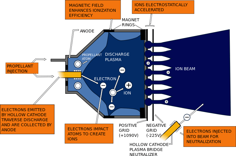
In an ion drive, the xenon isn’t a fuel. It isn’t combusted, and it has no inherent properties that make it useful as a fuel. The energy source for an ion drive has to come from somewhere else. This source can be electricity from solar cells, or electricity generated from decay heat from a nuclear material.
Ions are created by bombarding the xenon gas with high energy electrons. Once charged, these ions are drawn through a pair of electrostatic grids—called lenses—by their charges, and are expelled out of the chamber, producing thrust. This discharge is called the ion beam, and it is again injected with electrons, to neutralize its charge. Here’s a short video showing how ion drives work:
Unlike a traditional chemical rocket, where its thrust is limited by how much fuel it can carry and burn, the thrust generated by an ion drive is only limited by the strength of its electrical source. The amount of propellant a craft can carry, in this case xenon, is a secondary concern. NASA’s Dawn spacecraft used only 10 ounces of xenon propellant—that’s less than a soda can—for 27 hours of operation.
In theory, there is no limit to the strength of the electrical source powering the drive, and work is being done to develop even more powerful ion thrusters than we currently have. In 2012, NASA’s Evolutionary Xenon Thruster (NEXT) operated at 7000w for over 43,000 hours, in comparison to the ion drive on DS1 that used only 2100w. NEXT, and designs that will surpass it in the future, will allow spacecraft to go on extended missions to multiple asteroids, comets, the outer planets, and their moons.
Missions using ion propulsion include NASA’s Dawn mission, the Japanese Hayabusa mission to asteroid 25143 Itokawa, and the upcoming ESA missions Bepicolombo, which will head to Mercury in 2017, and LISA Pathfinder, which will study low frequency gravitational waves.
With the constant improvement in ion propulsion systems, this list will only grow.
Recent progress and perspectives of space electric propulsion systems based on smart nanomaterials
Abstract
Drastic miniaturization of electronics and ingression of next-generation nanomaterials into space technology have provoked a renaissance in interplanetary flights and near-Earth space exploration using small unmanned satellites and systems. As the next stage, the NASA’s 2015 Nanotechnology Roadmap initiative called for new design paradigms that integrate nanotechnology and conceptually new materials to build advanced, deep-space-capable, adaptive spacecraft. This review examines the cutting edge and discusses the opportunities for integration of nanomaterials into the most advanced types of electric propulsion devices that take advantage of their unique features and boost their efficiency and service life. Finally, we propose a concept of an adaptive thruster.
Introduction
Major progress in robotics and microelectronics, as well as significant advances in nanoelectronics, make it possible to efficiently explore both near Earth and deep space with small spacecraft1. These spacecraft and ultra-small satellites, sometimes referred to as Cubesats, are poised to permanently transform the global economy and mankind’s approach to space exploration. In particular, small spacecraft have dramatically lowered the initial capital cost of deploying on-orbit capability. Historically, only large companies and government organizations could meet the cost (>$100M USD) of manufacturing a functional space asset, purchasing the launch, and acquiring insurance. Small satellites, enabled by the miniaturization of electronics and related systems, have brought the entry capital barrier down to as low as $1M USD. This has allowed new players, such as universities and small companies, to acquire custom on-orbit assets. Launch providers have added fuel to this fire with the introduction of numerous, low-cost secondary payload rides.
Small satellites and Cubesats, as well as their related capability have touched all aspects of human activity. Private investors have embraced the use of the small surveillance platforms to monitor natural resources and commerce activity. These companies include Terra Bella (formerly Google Skybox) and Planet. In response to the growing demand for small satellite technology, a variety of small businesses has appeared to support the component needs of satellites suppliers. Cubesats exist already on almost every University campus and span the spectrum from large research institutions such as the Georgia Institute of Technology to small community colleges, e.g., Medger Evers College. A plethora of organizations associated with defense and surveillance actively use small satellite assets to conduct their intelligence missions. The Air Force continues to build the skilled workforce through sponsorship of University Nanosat Program. Civil space organizations have focused multiple programs and solicitations on Smallsat technology development as well as on leveraging small satellite platforms to perform unique science missions. Multiple NASA centers develop and deploy small satellites and Cubesats from the International Space Station. Box 1 shows the growth in the number of publications related to satellites and relevant systems, reflecting a strong increase in interest in this field.
While small satellites have enjoyed initial success, the civil sector requires more sophisticated spacecraft to perform remote Earth sensing, precision agriculture, monitoring erosion and sea pollution, precision weather prediction, navigation, global satellite-based communication systems, and many other tasks that could provide a considerable boost to the efficacy of these areas of human activity2. Moreover, smart robotic orbiters and landers could efficiently explore other planets including Venus and Mars. Apparently, the next steps in the use of small satellites and Cubesats to perform civil space missions could be divided into two categories, (i) exploring our solar system and beyond, and (ii) leveraging the near-Earth space. Missions in our solar system include further exploration of the Moon3, exploration of Mars4,5, and sending long-life probes to planets, comets, asteroids6, and deep space7. In parallel, intense use of near-Earth space will continue to benefit the entire mankind—from using small space assets for advanced communication, global internet access, precise weather prediction, asteroid tracking, global positioning systems, to near-Earth space exploration (e.g., registration of radiation and corpuscular fluxes, and their effect on communication systems and weather)8,9. These missions demand very sophisticated, autonomous equipment that reliably operates within the hostile space environment—very low and high temperatures, extreme radiation, impact by high-speed dust particles, and other severe conditions. In this review, we provide a brief literature survey on the unique features of nanostructured materials in the context of their application in electric propulsion (EP) systems and thrusters, with a strong focus on Hall-effect and gridded ion thrusters. In particular, the application of vertically aligned nanotube patterns, nanotube- and graphene-based nanomaterials, as well as complex metamaterials involving nanoscaled structures and related physical effects are discussed. Moreover, the concepts of adaptive and self-healing thrusters are proposed, presenting systems capable of self-adjusting the operation mode. Development of a new generation of miniaturized EP platforms is expected, based on the ingression of nanomaterials into space technology.
Electric propulsion systems as the first choice
Wide application of nanoapproach in space technology could be a possible way to realize smart, nanoscale spacecraft. According to the NASA’s 2015 Nanotechnology Roadmap Initiative, nanomaterials and related techniques should constitute a base for the new generation of spacecraft10. Evidently, EP systems are the primary candidates for driving the development of these novel spacecrafts—see Boxes 2 and 3 to learn more about design and impressive benefits of the EP platforms and the two most advanced types of EP devices, namely Hall-type and gridded ion thrusters.
Why is EP unique? Powerful liquid and solid propellant rocket engines are commonly used during the first stages of space flight. Despite relatively low specific impulse11 (i.e., propellant exhaust velocity), they feature very high thrust-to-weight ratios. Thus, they are most suitable for launch applications and reaching orbital velocity. In contrast, most long-duration missions imply low thrust but require high specific impulse to efficiently control the orientation and location of the spacecraft. Unfortunately, small chemical rocket engines deliver very low specific impulse at low thrust levels. In contrast, the EP that uses electrical energy to accelerate ionized propellant and delivers very high specific impulse is the leading propulsion solution for long-duration missions12. EP devices employ electrostatic or electromagnetic forces to accelerate the propellant and thus do not have physical limitations on their exhaust velocity.
In terms of specific impulse (which shows how efficiently the propellant is used), this means that EP can develop thrust at a very low propellant mass flow rate, i.e., the mass of propellant required for the entire mission could be small. Such a system is the best candidate for long-duration spacecraft control13. Thrusters employing electrostatic methods of acceleration (specifically Hall- and gridded ion-type devices) are superior to other electric types due to low secondary losses of energy (e.g., for ionization of propellant and heating), and they are the most promising platforms for deep space and interplanetary flights. Other devices such as pulsed plasma thrusters14, magnetoplasmadynamic thrusters, and novel perspective approaches, e.g., the variable specific impulse magnetoplasma rocket (VASIMIR15, are also suitable for specific space tasks). It is important to remember that because EP devices use electrical power to accelerate the propellant, their operation is power limited.
The general aim of this review article is to demonstrate encouraging examples and possible approaches for boosting the performance and lifespan of spacecraft EP systems by the wide-and-wise application of nanoscaled materials and techniques in the most challenging, critical areas (see Fig. 1 for the most determined “bottlenecks” to be possibly resolved with the use of the next-generation nanomaterials and metamaterial systems). Eventually, we try to set the major directions and approaches for self-healing thruster platforms suitable for the ultra-long deep space missions.
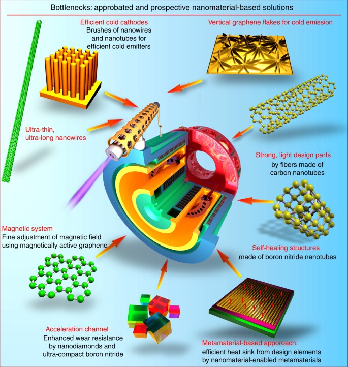
Bottlenecks and nanomaterial-based solutions for electric thruster. Reduction of the ion flux-related wear of an acceleration channel material and enhancement of discharge efficiency by using, e.g., nanodiamond coatings and ultra-compact boron nitride; enhancement of cathode efficiency by using cold emission insets made of dense brushes of long, ultra-thing nanotubes, nanowires, and vertically oriented graphene flakes; optimization of the magnetic circuit by the use of magnet-active graphenes; application of light, durable materials made of carbon nanotube yarns for the propulsion system parts are among the major challenges
Hall-type and ion thrusters as the two main candidates
Hall-type and gridded ion thrusters are among the most advanced, mature EP technologies with space-proven, relatively long flight heritage; some prominent EP-driven missions are described in more detail below. Specifically, a Hall-type thruster is a device that uses the closed electron drift, so-called Hall current, as the principal physical effect to drive the main processes in the discharge chamber, namely propellant gas ionization and ion flux acceleration via a static electric field16. Compared to other types of plasma thrusters17, the devices based on the closed electron drift possess very high efficiency due to low ionization losses and the absence of actively heated parts in the discharge zone.
The Hall thrusters are used for creating small (up to ~250 mN) thrust levels18,19, though no principal physical limitations are known to compromise the operation of Hall thrusters at power levels higher than 100 kW20 (actually, efficiency increases at higher power levels). These devices have also been successfully scaled down to powers lower than 100 W at μN-thrust levels21. Besides, Hall thrusters can produce a very large number (>104) of thrust pulses without undergoing maintenance and part replacement, with a very high (up to 40–50 × 103 m/s) exhaust velocity22,23.
In the gridded ion plasma thruster, the electric potential is applied to the acceleration mesh, and thus the ion flux is accelerated and expelled from the thruster through the mesh. Both types of thrusters are very efficient devices for plasma production and acceleration. One significant difference between them is the current density limitation applied to the ion thruster due to the space charge limitation; this results in a larger ion thruster diameter compared to the Hall thruster. More details and illustrations can be found in Boxes.
Are they flying? The EP systems are already performing missions in space, thus accumulating invaluable experience and paving the way for the future. In fact, these systems possess a long history that started in 190624, or more realistically, in 195025. The first ever EP flight tests using ablative pulsed plasma thrusters took place in 196426. The first flight demonstration of the Hall thruster occurred in 1971, and the subsequent flights have proven the high reliability and efficiency of this type of the device27. Launched in 1998, the Deep Space 1 probe was accelerated by >4000 m/s using 2-kW ion thrusters28, which spent about 70 kg of xenon exhausted at a speed of 4 × 10⁴ m/s for near 2 years29. A similar system was installed on the gravity-ocean circulation explorer GOCE satellite in 200930. Currently, the SSL SPT-100 Hall thruster subsystem is flying on 17 geostationary communication spacecraft, with an accumulated total flight time of 40,000+ h9. ADD Aerojet Rocketdyne on LM AEHF satellites Eutelsat has demonstrated the EP system capabilities on two platforms (EUTELSAT 16C and KA-SAT), and launched the full-electric platform EUTELSAT 115 West B in March 2015, for which EP was used for complete electric orbit raising. Two more platforms (EUTELSAT 117 West B and EUTELSAT 172 B) will be also launched31. The PROITERES-3 nanosatellite equipped with 30-W Hall thruster is planned for a one-way trip to the moon from low orbit21. However, the long-expected era of electrically driven spacecraft has yet to be realized, where the main obstacle lies in the relatively high consumption of electric energy by the thrusters, requiring significant enhancement in the thruster efficiency32.
Recently, NASA has designed and performed the DAWN mission to investigate the two main-belt asteroids, Vesta and Ceres, which are among the most massive small planets. The DAWN mission was actually the ninth project of the Discovery Program. Except for the gravitational maneuver in the Mars’ gravitational field, this mission was powered exclusively by an EP system. The entire post-launch velocity gain ΔV required for the heliocentric transfer to Vesta, then retardation to capture orbit at Vesta, additional acceleration for changing orbits at Vesta, final escape from orbit Vesta, then transfer to Ceres by heliocentric orbit, retardation to capture orbit at Ceres, and the acceleration to change orbits at Ceres was provided by the ion thrusters. The EP platform in this mission has ensured the total velocity gain of ~11 km/s, and ~400 kg of xenon was spent during the entire mission28,33.
Another important option for the application of EP systems is the control of low mass (up to 100 kg) and miniature (Cubesats, up to ≈1 kg) satellites that have a base form factor of a cube with the typical size of 0.1 m. An internationally adopted standard in this field is the “Cubesat” by California Polytechnic State University (CalPoly)34. Miniaturized but fully functional35, highly efficient modern electronics ensure a wide spectrum of capabilities even on such a small scale, thus enabling a great resource economy due to low-cost launching using, e.g., small airborne systems like the Orbital ATK Pegasus36. The propulsion systems used on Cubesats usually provide a thrust of up to 1 mN, with the consumed power of up to 100 W and the unit mass of several kg37,38. Recently, a so-called “satellite-on-a-chip” or “ChipSat” concept was proposed with the aim to explore near-Earth space using the ultra-miniaturized spacecraft in the form of monolithic semiconductor integrated circuits, with a weight not exceeding 0.1 g (“smart dust”)39, as well as picosatellites (0.1–1 kg), and femtosatellites (up to 0.1 kg)40. A large number of the ultra-miniaturized satellites (smart dust nodes) forming an actively interacting distributed network could provide a highly efficient solution for collecting, converting, and transmitting large amounts of information41. Gas and thermal thrusters are not applicable in this case, and an EP system may be the only possible option42.
Are they efficient? Yes, even at their present stage of development they are quite efficient. The efficiency of contemporary EP systems reaches 10–35% for the most common power range of 100–300 W43, downscaling (depending on the design) to 6–15% in the power range of 50–100 W44. Larger thrusters demonstrate higher efficiency, reaching 40–60%45 at a power range of 1–3 kW and even 65% for higher powers46—these are very large numbers for any heat engine. Nevertheless, significant advances in power efficiency and controllability, as well as service life are needed to make the EP systems the cornerstone of space propulsion capable of highly efficient, robust operation under severe space conditions for years.
As for now, significant efforts have been made to enhance the performance, service life, and reliability of the Hall thruster by means of sophisticated designs. Among others, the two-stage Hall thruster was designed and tested47. To ensure high performance at very high power levels reaching 100 kW, a multiple nested thruster designs have been demonstrated20. Other design solutions such as cylindrical and annular Hall thrusters were proposed for the miniaturized devices44. More details on the methodology and problems related to scaling down EP devices could be found in the relevant publications48,49. Nevertheless, further improvements are still required, where the major advancements should definitely come from the material field.
How can we boost their performance and service life? The performance of contemporary EP devices can be boosted by the application of ultra-novel nanoscaled materials and systems to significantly enhance work capabilities and efficiency of all subsystems of the EP system and the most important units of thrusters, including ion and Hall thrusters specifically50. Significant progress has already been achieved in the optimization of the design, geometry, and magnetic field configuration of the thrusters; however, further progress is vitally required to launch plasma thrusters into orbit of a commercially efficient life, and we propose and review here the use of surface-bound nanostructures and nano-engineered surfaces as a next-generation approach to the development of EP systems. Evidently, all the main challenges, namely efficiency, lifetime, and process control of the thruster can be significantly enhanced by the use of nanoscaled materials and techniques.
There are other types of plasma thrusters potentially suitable for Cubesats and even smaller satellites. While Hall-type and gridded ion thrusters enjoy a relatively established reputation among small orbit- and interplanet-tested systems, other types of EP devices are just at the start of their road to the stars. The rise of Cubesats and ultra-small (Picosats—<1 kg mass) satellites spurred global demand for micro-N propulsors, and the first launches have already proven their suitability and efficiency for the specific Cubesat tasks—precise positioning, orientation, and orbit keeping with µ-N pulses. These thrusters are designed to operate at ultra-small thrust levels, providing a superior level of control over satellite positioning and orientation; however, the material issues still play an important role in their advancement and integration into existing and emerging satellite systems51.
Nanomaterials in thrusters
Let us now examine how to boost the properties and characteristics of the thruster itself, which is the primary and critical sub-subsystem of the entire EP platform.
Acceleration channel—what is the main challenge? One of the major problems limiting the application of Hall thrusters in space is the erosion of the ceramic wall caused by the impact of the accelerated ion flux (Fig. 2)52. With the ion velocity reaching 10-–20 × 103 m/s, the wall wear is non negligible, significantly limiting the thruster life53. Currently, used boron nitride (BN) ceramics ensure remarkable operating characteristics but unsatisfactory service life;54 many researchers are currently dealing with this problem55. Design efforts have aimed to reduce the wall wear, for example, by using a cusp-type magnetic field that leads to a simplified (no internal ceramic wall) channel geometry, thus lowering integral wear; however, the wall material is at the heart of this problem. Table 1 provides a comparison of several most popular materials tested in the thruster conditions.
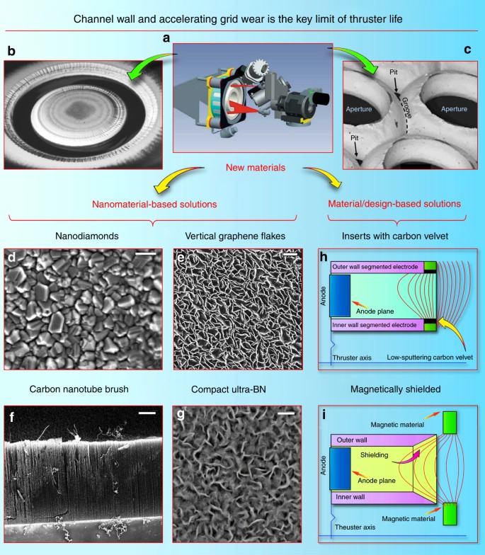
Nanomaterials to reduce erosion of accelerating grids and channels. Erosion measurement and analysis is not a trivial problem; a illustrates a Telemicroscopy Erosion Measurement System for 5-kW-class Hall effect thruster. Reproduced from ref. 125. (Copyright 2015 ERPS). b Erosion of the Hall thruster acceleration channel. Reproduced from ref. 126. (Courtesy Aerojet Rocketdyne, Inc., Copyright Aerojet Rocketdyne, Inc. 2010). c Erosion of the ion thruster acceleration grid. Reproduced from ref. 127. (Copyright 2008, IEEE). Wear damage of several millimeters results in a significant drop in thruster efficiency. Nanomaterials-based solutions: (d) surface morphology of nanodiamond films with nanocrystalls of 100 nm and a film layer of 600 nm were fabricated at 870 °C. Scale bar, 0.1 µm. Reproduced from ref. 128. (Copyright AIP 2012). Nanodiamonds were successfully tested in the thruster channel57. e Vertical carbon nanoflakes grown on an alumina membrane could potentially help to reduce wear. Scale bar, 1 µm. Reproduced from ref. 129. (Copyright 2014, Elsevier). f SEM image of the typical carbon nanotube brushes. Scale bar, 5 µm. Reproduced from ref. 130. (Copyright RSC, 2015). g A compact magnetron-deposited low-sputtering boron nitride coating (synthesized in authors’ laboratory). Scale bar, 400 nm. This material has demonstrated the total wear rate of several nm × h−1, which corresponds to only 20 µm per 10,000 h. To compare, the typical erosion numbers are: Al2O3—0.3 µm/h, diamond—0.7 µm/h, SiC—0.8 µm/h, and BN—1.1 µm/h131, with 5000 h service time as a good benchmark for today’s thrusters, such as a Snecma Safran Group device that completed a successful mission to the Moon132. Material/design-based solutions: (h) schematics of a Hall-type thruster channel with insets covered with the low-sputtering carbon velvets67, 133. i The magnetically shielded channel solution requires precise tuning of the magnetic field, but significantly reduces the channel wall sputtering yield74, 134
Ultrananocrystalline
diamond may be a promising approach to prolong service life. The first
possible attempt to reduce wall erosion is to use thin sputtered films
of a nanocrystalline wear-resistant material56
such as diamond. Polycrystalline chemical vapor-deposited diamond films
were tested on Hall thruster walls (on wear-affected areas), and have
demonstrated significantly better wear resistance without notable
degradation of the thruster performance and thrust57. Evidently, the choice of the wall materials
significantly affects the plasma discharge via changes in the secondary
electron emission, and more efforts should be applied to study all
aspects of this process; nevertheless, these encouraging results attract
special attention to the crystalline nanodiamond, which can be a very
promising candidate to address a significant increase in wear-limited
life. Indeed, it was demonstrated that the as-grown ultrananocrystalline
diamond films have wear coefficients roughly two orders of magnitude
lower than those of microcrystalline diamond films of comparable
thickness58. Other tests59
have demonstrated absent or negligible wear of the ultrananocrystalline
diamond films under conditions when other wear-resistant parts suffered
significant wear rates60. In mechanical tests, coatings of ultrananocrystalline diamond have demonstrated an order of magnitude longer lifetime61.
Such inspiring results obtained for the ultrananocrystalline diamond
suggest the need for extensive tests of ultrananocrystalline diamond
films for the wear reduction of the Hall channel walls. It should be
noted that the morphology and surface condition of the
ultrananocrystalline diamond strongly affects its tribological behavior62,
while the properties of the Hall thruster itself critically depend on
the wall conditions. Therefore, careful design and both experimental and
analytical examinations will be needed to implement this sophisticated
nanomaterial in the EP technique, and thorough testing of the actual
effect of energetic ion flux directly in the thruster channel is
required. Nevertheless, breakthrough results may be expected and the
thruster efficiency may be significantly boosted.
Even more sophisticated nanomaterial with the promising wear-resistance properties was also demonstrated. Specifically, the hot-filament chemical vapor deposition was used to synthesize nanocrystalline diamond-coated silicon nitride ceramics63. This approach may be useful for enhancing the thruster wall wear resistance and simultaneously adjusting the acceleration process parameters, such as wall conductivity, roughness, secondary emission coefficient, and others that directly influence the discharge64.
Carbon can be also used for channel enhancement. One more promising approach to reduce channel wall erosion is the use of carbon-based nanostructured materials and surface structures. Carbon exhibits a very low sputtering rate under the action of ion flux, as compared with the commonly used BN ceramics65. Along with this, the secondary electron emission yield of carbon is also lower than that of BN, and this is also a useful feature that can be a factor in Hall thruster operation66. We should stress that BN demonstrates one of the best performances as a wall material, so at the first stage, the aim should be the design of the material that can at least preserve the efficiency of BN state-of-the-art thrusters. On the other hand, increase of wear resistance by the factor of 2 or 3 due to the wear-resistant carbon films67 is attractive for enhancing the Hall thruster lifetime.
Carbon nanotubes are also a promising technique to enhance channel wear resistance. It is known that the graphene and graphene-based nanostructures, such as carbon nanotubes, are very strong (strongest known in nature) materials68. The carbon nanotubes were also tested for resistance against ion flux erosion. Specifically, the multiwall carbon nanotubes were tested as the protective coating against plasma erosion in advanced space propulsion systems. The polycrystalline diamond film was compared with multiwall nanotubes, amorphous carbon, and BN films69. Two types of nanotubes were investigated, including vertically aligned nanotubes and those horizontally laid on the substrate surfaces. Only diamond films and vertically aligned nanotubes survived erosion by 250 eV krypton ions of a flight-quality Hall thrusters69.
It should be stressed that the use of carbon nanotubes in the thruster is presently at the stage of an advanced concept that requires strong efforts to check feasibility. Indeed, many properties specific to carbon nanotubes, such as a decrease of the secondary electron emission in vertically aligned structures and electrical conductivity of carbon nanotubes can degrade the thruster characteristics. On the other hand, carbon nanotubes are very attractive due to the properties of the carbon material, and that material should obviously undergo active testing in EP devices, taking into account the above-mentioned encouraging results on wear resistance.
Thus, the dense brushes of vertically aligned nanotubes demonstrate quite attractive and fascinating properties when tested for wear resistance under the action of energetic ion flux in the Hall thruster channel. Notably, the carbon nanotubes are conductive and can change the acceleration mechanism (the wall conductivity is not an inadmissible condition, but it significantly affects the process70). Undoubtedly, the first encouraging experiments67,69 force further complex investigations to cast light on the application of carbon nanotube brushes and other graphene-containing materials in EP engineering.
Graphene nanowalls is one more material potentially capable of enhancing channel wear resistance. Along with the carbon nanotubes, graphene and graphene flakes may be attractive for enhancing the channel wall wear resistance. Graphene is the strongest material in nature and carbon and carbon nanotubes are particularly resistant to ion sputtering; this makes the surface-grown graphene flakes (nanowalls) extremely attractive candidates for wear-resistance testing in the Hall thruster channel. Dense patterns of carbon nanowalls can be formed directly on the ceramic surface, with or without metal catalyst particles71 if required. Direct growth on ceramic and metallic72 materials is also possible73. The exemplary graphene patterns grown on alumina are shown in Fig. 2, left panel. They consist of nearly vertical graphene flakes attached by one edge to the face surface of the ceramics, with the other edges being open. Graphene nanowall patterns have not yet been subjected to extensive ion flux and wear testing in real EP devices, but positive results of the experiments with other carbon-containing, and especially graphene-like and diamond-containing nanostructures, encourage further work in this direction. Similar to other ultramodern techniques, graphene and nanotubes should find their deserved place in EP technology.
Table 1 shows a list of the presently used and tested materials and nanomaterials for application as a coating on the acceleration channel. Among then, the newly synthesized ultra-BN (uBN) material fabricated by plasma-assisted CVD (chemical vapor deposition) process demonstrates excellent wear and discharge efficiency characteristics. With extremely low surface roughness and very low erosion coefficient (the total wear rate of several nm × h−1, order of magnitude lower than that of BN), the ultra-disperse uBN appears to be the best candidate for the highly efficient, long-life thrusters. The operational tests of this material are in progress, and a flight test is planned.
Apart from the material-related approaches, a so-called magnetic shielding technique was recently demonstrated74. Sophisticated selection of the shape of the magnetic field at the exit of the accelerating channel, and the proper profiling of the channel exit ensure a significant decrease in the intensity of ion bombardment to the channel walls, and hence, substantial decrease in the wear of channel walls. As a result, the service life of the channel can be essentially increased, thus significantly prolonging the thruster lifespan without notable drop in the performance characteristics. Schematics of the magnetic shielding technique is depicted in Fig. 2, right panel. Importantly, magnetic shielding allows to operate the thruster at higher voltage levels, i.e., the specific impulse that is in general proportional to the discharge voltage could be increased. Moreover, magnetic shielding partially precludes electrons from contacting with the walls and hence, allows changing the wall material (to metals or carbonaceous materials, or cheaper ceramics) without reducing the thruster characteristics. On the other hand, this technique requires more complex magnetic topology, which could make the EP system somewhat more complicated and potentially less reliable. However, potential significant benefits of this technique call for further studies since the high-voltage operation requires new resistant materials even in the magnetic shield mode. Further, both new materials and sophisticated magnetic field topology are necessary to achieve the dual-mode operation described in more detail below75.
Longer life and higher cathode current via advanced materials
Cathode is the second electrode used in any type of static thruster to apply negative potential to the discharge zone and in some cases, to supply the flux of electrons to the discharge zone where they are magnetized, as well as to compensate the space charge of (non-magnetized) ions; that is why the cathodes on Hall thrusters are sometimes called neutralizers. As a rule, a couple of cathodes (a working one and a spare one) are usually installed outside of the main body of the thruster, as shown in Box 2. Cathodes may also be installed well outside the thruster (to ensure better thruster characteristics) and thus will require strong protection76. Optimization of the cathode position is required to ensure the highest thruster performance characteristics77.
The cathode in the present-day thruster (see the schematic of the commonly used thermosemissive cathode in Fig. 3a) is a very power- and current-loaded device, which should provide reliable service for very long periods of time. One of the typical cathodes with the LaB6 electron emitting insert (one of the most common materials used in the emissive cathodes) was designed to ensure the lifetime of 100,000 h at the discharge current of 40 A, thus can be used to power a 12.5-kW Hall thruster under development for the proposed Asteroid Redirect Robotic Mission78. The cathode can be used as a low thrust thruster itself79. Cathode erosion also represents a problem reducing the service life80.
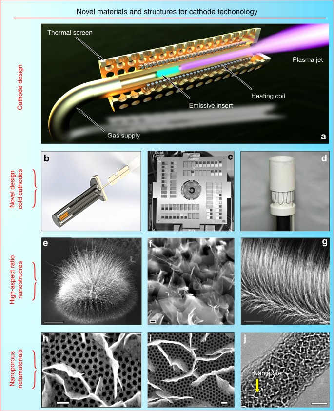
Novel materials for cathode technology. a Schematic of the commonly used thermosemissive cathode. The typical electron emission cathodes incorporate a central tube (1–5 mm dia.) with a porous highly emissive insert (typically lanthanum hexaboride LaB6) and a heating coil installed around the tube. Gas (with the flux rate of several percentage points of the total thruster propellant consumption) is supplied into the central tube, which is heated by the coil. The emissive insert ensures thermoionization of the gas exiting the cathode orifice. When the thruster is working (discharge is sustained in the chamber), plasma forms a narrow jet connecting the cathode orifice with the main discharge zone, and electrons pass to the discharge via the plasma jet. The cathode includes a thermal screen to reduce the heat loss to space due to ionization. In addition, it incorporates elements and parts to attach the cathode to the thruster and the gas feed system. b New highly efficient cathode with a cold nanoporous metal emissive element (under testing at the PSAC/SPCS Lab). c Carbon nanotube cold cathodes in a Hall effect thruster environment. Reproduced from ref. 135. (Copyright 2013, ERPS). d Classical cathode with a heating coil and an emissive La-B insert. Reproduced from ref. 136. (Copyright 2011, ERPS). e Cluster of carbon nanotubes serving as a cold emitter. Scale bar, 50 µm. Reproduced from ref. 90. (Copyright 2012, Elsevier). f Nanocrystalline graphite in an advanced field-emission spacecraft cathode. Scale bar, 200 nm. Reproduced from ref. 137. (Copyright 2011, ERPS). g Long nanotubes on silicon. Scale bar, 15 µm. Reproduced from ref. 90. (Copyright 2012, Elsevier). h, i Vertically aligned graphene flakes grown directly on the nanoporous alumina. Scale bars, 200 nm. Reproduced from ref. 129. (Copyright 2014, Elsevier). j Single-crystalline MoO3 nanowire. Scale bar, 10 nm. Reproduced from ref. 93. (Copyright 2012, RSC)
Thus, the key challenges for the cathode (and consequently possible directions for the enhancement of thruster efficiency via upgrading the cathode unit) consist in the reduction or total elimination of propellant consumption via the cathode, significant boost of the cathode service life, and the reduction of heat loss from the incandescent parts.
Can nano help here? Let us examine how nanomaterials and nanotechnology can help achieve these goals.
Reduced gas consumption may be ensured through the use of nanoporous materials, nanotubes, and graphene. The best solution for this problem is the total elimination of gas flux through the cathode by using high-emissive materials and surface structures. Numerous tests have demonstrated that usual solid and microporous materials cannot ensure notable enhancement of characteristics compared with the commonly used LaB6 material. However, encouraging experimental results have been obtained by testing various nanostructured and surface-engineered materials, such as nanoporous metal emissive elements (Fig. 3b). Carbon nanotubes were also successfully tested as field-emission electron sources operating without or at reduced gas supply81 (Fig. 3c shows the photograph of carbon nanotube cold cathode installed on a Hall effect thruster). Moreover, multiwall carbon nanotube emitters were tested directly for the use in spacecraft cathode units;82 the tests were conducted specifically for the operation in the Hall thruster plume environment83. Other nano-engineered materials also demonstrated promising electron emission properties, e.g., ultrananocrystalline diamonds84 and nanocrystalline diamond-coated silicon tip arrays85. Nano- and micro-engineered materials relevant to EP were also tested for their electron emission capabilities86. Vertically aligned graphene87 has also demonstrated inspiring results in electron emission tests88. Investigations related to the reliability and failure mechanism of the carbon nanotube-based cathodes are also undergoing active exploration89. Therefore, carbon nanotubes (both single- and multi-walled) and vertically aligned graphene flakes are good candidates for significantly enhancing thruster efficiency due to the propellant-free regime (we recall here that the propellant consumption by the conventional incandescent cathode can reach 10% for small thrusters, and usually accounts for 3–5% of propellant consumed for larger devices). In spite of many successful experiments referenced here, more efforts are required to utilize the full potential of vertically aligned nanostructures in cathode-related applications, and newly developed nanostructures and patterns can be much more efficient than those already tested classical cathodes with a heating coil and an emissive La-B insert (Fig. 3d).
An example of a novel and potentially efficient nanomaterial for cathodes is the cluster-grown carbon nanotubes and nanocrystalline graphites. These clusters could be arranged into various shapes by a simple mechanical drawing (using e.g., mechanical tools or a laser beam) of the required configuration on the surface. Figure 3e, f, g show the SEM (scanning electron microscopy) images of nanotube and nanocrystalline graphite clusters. Such aggregates are extremely promising for emission-related applications. Scanning and transmission electron microscopy characterizations show that the longest nanotubes reach several hundred microns in length, the array density reaches 1000 nanotubes per l μm2, and diameters of the nanotubes were in the range of 15–50 nm, with up to 20 walls. Importantly, dense linear brushes of nanotubes could be produced over the entire sample size of 10 mm. More detail about the growth process can be found elsewhere90. Further studies of these and other nanotube and graphene patterns and surface structures are needed to make a definitive conversion from contemporary propellant-consuming cathodes to novel, cold, propellant-free nanomaterial-based cathodes. More examples and a detailed description can be found in Fig. 3.
When the propellant-free design is inapplicable, complex nanostructure-based surface systems (metamaterials) may be proposed for application in thruster cathodes, with one of the example systems shown in Fig. 3h, i. A dense pattern of the vertically aligned graphene flakes was grown on the nanoporous91 alumina membrane. Propellant can be supplied directly through the nanoporous alumina, and electrons will be emitted from the acute edges of the graphene, which are emission-capable structures as was demonstrated in direct experiments88.
Longer life of cathode could be also reached by the use of ultra-nanoporous inserts. Emissive inserts work when electrons exit an emissive material from the surface; hence, larger surface area per volume unit of the insert could be beneficial due to the lower required heated volume and more efficient electron emission. Here, we demonstrate an example of ultra-nanoporous highly-crystalline nanowires with uniformly distributed nanopores in the 3 nm range produced by electron beam exposure (Fig. 3j). In the example, single-crystalline MoO3 nanowires were synthesized by a simple, environmentally friendly plasmoxy-nanotech process92 by direct exposure of a pure Mo foil to reactive oxygen plasmas in a Pyrex glass reactor. After synthesizing the single-crystalline MoO3 nanowires, they were transferred to the transmission electron microscopy grid for the electron beam irradiation. This method is based on the electron beam-driven oxide-to-sub-oxide and then sub-oxide-to-metallic transition that can be controlled by the electron beam exposure. The diameters of the resulting pores range from 2 to 5 nm, with a Gaussian-like distribution and an average size of around 3.6 nm. More details on the process and performed characterizations can be found elsewhere93. This nanomaterial brings together several beneficial properties, namely a unique ultra-nanoporous structure (nanopore size of 2–5 nm) and an extremely high porosity coefficient reaching 0.75. This technique can potentially be used to produce other materials, including those suitable for the emissive inserts, and very efficient inserts may be fabricated.
Nanoscaled metamaterial could help to reduce the heat losses. The incandescent cathode wastes a great deal of heat energy through radiation from the cathode’s hot parts into space. However, ideally, the entire heat generated in the cathode should be used within (at the emissive insert) and should not be released from the outer parts of the unit. Any type of currently used heat protections essentially provides passive protection. Using nanoscaled metamaterials, active heat protection physically based on heat pump principles can be designed. Specifically, external energy should be spent to transfer the heat from colder parts to heated parts by, e.g., nanoscaled high-temperature metamaterial capable of reversal heat transmission94. During the metamaterial operation, an electrical potential dependent on the distance between surfaces and the current density is applied between the anode and the cathode to sustain the current in the gap. As a result, heat may be transferred from the hot surface directly to the colder part by the electron current in the gap, i.e., this metamaterial works as an electronic heat pump. As a result, heat that leaks from the hot cathode to space can be significantly reduced. We stress that this is only a concept under active investigation95. Further investigations will be needed to design, test, and implement the novel heat-transferring systems in the material form factor. A schematic of the metamaterial proposed for the active heat pumps is shown in Fig. 4.
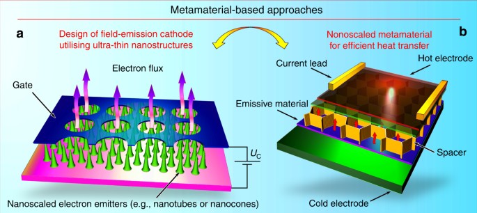
Metamaterial-based approaches. a Design of a metamaterial-inspired cold electron emitter incorporating the dense array of emitting elements (e.g., carbon nanotubes or metal-tipped nanocones) grown directly on the electrode, and the gate electrode with µ-sized orifices. Due to strong electric field enhancement on the long nanosized structures, significant current densities could be obtained without external heating. b Design of the nanoscaled metamaterial capable of reversal heat transfer by electron emission. This structure may include a nanoporous membrane (a porous insert) capable of containing some amount of a highly emissive material usually working in a liquid state (e.g., cesium). The nanoporous membrane with the emissive material in pores is placed directly onto the solid cathode, and the spacer separates this membrane and the anode with the low-emissive material. The low-emissive material (e.g., tungsten) covers the anode surface. The cathode (the cold electrode in green) has a temperature lower than that of the anode (the hot electrode in red). Electron current emitted from the cathode flows through the inter-electrode gap to the anode. It is evident that such metamaterials could create strong heat barriers in the systems where heating over some limit (e.g. Curie temperature) should be avoided. Reproduced from ref. 138. (Copyright 2016, Wiley)
Adaptive and self-healing thruster via nanomaterials
As previously mentioned, the nature of the wall material can be used to classify Hall-type thrusters as TAL featuring metallic channel walls, and thrusters with ceramic walls (stationary plasma thruster, SPT). These two types exhibit slightly different characteristics and require somewhat different design approaches, and as such, these devices could occupy specific application niches and be successfully used in space exploration for various missions. In general, the total difference in performance between ceramic-walled SPT-type thruster and metal TAL is not so significant. Nevertheless, both types are attracting attention, and among other advantages, TAL can ensure efficient operation at higher (up to several kV) voltage, so the specific pulse (exhaust velocity) will be higher. In turn, this may be advantageous for the missions requiring elevated specific impulse at somewhat lower thrust, such as orbit keeping or debris removal96 for several years at limited onboard power and limited mass. At present, the TAL-type thrusters are underexplored, yet numerous studies indeed demonstrate their better operability at significantly increased voltages97,98. Even within the same thruster type, the wall material characteristics may influence thrust, exhaust velocity, and thruster efficiency99,100.
Evidently, TAL is not congruent to a standard SPT thruster with conducting walls, and apart from the wall material state, some other adjustments (e.g., shift of the anode to shorten the discharge zone to the TAL-optimized configuration, reshaping the magnetic field by switching coil sections, and so on) will be required to ensure efficient TAL operation in the proper mode, i.e., in the anode layer regime; nevertheless, such transformations appear to be quite attainable in flight101.
Is it possible to actively control processes in thrusters by nanomaterial-based techniques? Evidently, many of the present-day nanomaterials and surface-engineered systems could be tested for the active control of the thruster operation. Acceleration channels made of various materials such as solid BN, diamond- or ultrananocrystalline diamond-coated walls, or carbon nanotubes/graphene-protected surfaces can exhibit notably different surface morphologies, roughness, and electrical conductivity, and importantly, reasonably distinct electron emission features also determined by the presence of acute tips (e.g., on carbon nanotubes), sharp edges (e.g., on graphene flakes), and sharp facets (e.g., on nanodiamond crystals). Undoubtedly, control of such a set of unique properties can lead to thrusters with a wide operational range, and moreover, could allow adaptive switching between the operational modes.
Importantly, most of the nanostructures and nanomaterials mentioned above are routinely fabricated, or could be fabricated using low-temperature plasmas with properties that are quite similar to plasma properties within operating Hall thrusters, specifically: plasma density of ≈1018–1019 m−3, electron energy up to 10–20 eV, and process voltage of about several hundreds of volts. Granted that different feedstock gases must be used to accomplish propulsion or nanosynthesis, we still find the similarities quite encouraging. Indeed, Hall thrusters have already been successfully tested for nanofabrication, and hence, desired nanostructures and nanomaterials could be in principle synthesized directly in the discharge (acceleration) channel.
Thus, we propose the concept of the so-called adaptive thruster, i.e., the thruster that is capable of changing the main discharge type (thruster type) by actively adapting the channel wall parameters by synthesizing required nanomaterials in its own discharge, then depositing them onto specific locations inside the channel, and finally modifying the channel wall surface characteristics by direct interactions with its own channel plasma. In more detail, the electric, magnetic, and gas supply systems of the thruster should be designed and tuned to be capable of ensuring temporary transition of the discharge from acceleration to nanosynthesis mode (changing the gas composition by adding the nanomaterial precursor such as, e.g., methane and hydrogen for carbon nanotube, graphene, or diamond synthesis, and preprograming synthesis protocol) to ensure optimum nanomaterial nucleation and growth conditions, and restoring discharge to the acceleration mode after adjusting the channel wall to the new required thrust/velocity conditions.
Graphane can be a key material to realize this task. The ability of switching between TAL and SPT operational modes is a possible implementation of an adaptive thruster concept. As the wall material (a ceramic or a metal) is the major discriminant of these modes, the thruster ability of adapting the conductivity of its own wall material would enable the realization of adaptive features. For instance, hydrogenation of the surfaces of graphene flakes on the channel walls by the thruster discharge plasma may ensure quick and reversible transition from insulating to conductive states and vice versa, thus would provide the ability to switch between TAL and SPT regimes directly in flight and possibly, without interruption of the thruster operation. Indeed, it was already demonstrated that graphene can react with atomic hydrogen, and this reaction transforms graphene (which is a perfect electrical conductor) into graphane, an insulator made out of a two-dimensional compound of carbon and hydrogen (i.e., hydrogenated graphene)102. This reaction is also reversible, and the graphene structure is maintained when graphane is formed by attaching hydrogen atoms to graphene. Importantly, this reaction requires low-temperature plasma similar to that present in the Hall thruster discharge. In the original experiment103, 10% admixture of hydrogen in argon was used to convert graphene into graphane. Thus, by changing the plasma parameters in the thruster discharge, it is possible to change the conductor/insulator state of the acceleration channel surface by depositing graphene flakes. Xenon, which is commonly used in EP is similar to argon (both are inert gases with close ionization potentials and both sustain the discharge in crossed E × B fields at similar voltages), could be considered as suitable for a similar hydrogenation process. The hydrogen admixture in the gas of an operating thruster could be short, since only surface hydrogenation is required. As hydrogen source, metal hydrides (i.e., MgH2) can be used. At present, there is no scientific evidence regarding graphane behavior under the effect of the energetic ion flux, but encouraging results show that graphane is relatively stable (as it requires annealing for at least 24 h at 450 °C)103. Both vertically aligned graphene flakes, as well as graphene-like inlaying films can be proposed for adaptive thruster applications. In any case, the use of such materials should be explored due to the potential importance of the proposed in-operation and in-flight conversion of TAL to SPT.
Alternatively, an insulating film could be temporarily deposited onto the metal walls to transform a TAL-type device into a SPT-type. For this purpose, a small amount of silane (silicon and hydrogen containing gas, SiH4) and oxygen (or e.g., water vapor) can be premixed with the inert propellant (xenon). Indeed, it was already experimentally demonstrated that addition of silane (10 p.p.m. only) in the low-temperature plasma results in the efficient nucleation of silicon nanocrystals with the characteristic size of several nanometers104. Figure in Box 4 shows the experimental setup, as well as a photograph of the discharge and a scanning electron microscopy image of the nucleated silicon nanoparticles (mean diameter <5 nm). By tailoring the plasma properties, different nanoparticle characteristics, such as chemical composition and crystal structure, can be achieved. Oxidation can then be easily achieved with a very small amount of oxygen or even water vapor105.
The application of a thin metal film onto the channel wall surfaces from the discharge plasma is another approach to adaptive thruster systems. Indeed, this approach will require admixture of a metal-containing gas106 or evaporated metal-containing liquids107 capable of producing suitable metal precursors in the discharge. A metal film deposited onto the wall surface will ensure the transition from insulating to conductive states, but the wear resistance of pure metal is low and thus could be used for short-term regime switching.
Deposition of such oxidized nanoparticles onto the metallic walls of the acceleration channel will create electrically insulating layer and thus transform the TAL device into SPT. Notably, Hall thrusters with a significant addition of silica on the channel walls is quite functional, albeit with somewhat lower efficiency.
Is it possible in a real thrusters? Yes, provided that an efficient control over the processes in plasma-wall sheath is ensured, e.g., by the magnetic shielding that was encouragingly demonstrated for the thruster channel. Proper control of the plasma configuration108 could make it possible to temporarily separate the main discharge zone from the nanoparticle nucleation and deposition area, thus ensuring direct growth of the nanostructures in the discharge and the following deposition onto walls. Extended experimental and theoretical studies will be required to bring these concepts to life.
Using similar design solutions, it is possible to fabricate electrodes with, for instance, thin layers of carbon mixed with layers of traditional BN. Such sophisticated structures enable active control over the near-wall conductivity109, and hence, enhance the discharge and ion acceleration. Furthermore, the replacement of thin carbon layers with the graphene (and possibly, multi-walled graphene flakes110 could potentially enhance the characteristics due to higher mechanical strength, as well as electrical111 and heat conductivities, intrinsic to graphene112).
Perspective
The NASA’s 2015 Nanotechnology Roadmap includes, among other important concepts, a new paradigm of paramount importance, a so-called concept of a self-healing spaceship. This covers several mainlines, in particular self-cleaning surfaces, self-healing repair mechanisms, and self-repairing surfaces and materials. Initial research efforts by NASA and associated research institutions have demonstrated self-healing materials that were capable of repairing the punctures in several seconds113. Moreover, other possible self-healing approaches for EP systems were explored; at the thruster level, self-healing field-emission neutralizers (cathodes) for EP devices were developed by NASA in collaboration with Aerophysics, Inc. in the framework of the NASA Small Business Innovation Research (SBIR) contracts114.
The implementation of self-healing and self-restoring materials and systems to the entire spacecraft makes the self-healing approaches compulsory for subsystems such as thrusters that are the critical elements of the propulsion system. Furthermore, just the wear-affected acceleration channel walls that actually limit the thruster life are the ultimate elements to be examined in terms of incorporation of self-healing materials and techniques. Apparently, we are currently at the stage of problem formulation and determining the general angle-of-attack to ensure the development of the most general approaches; nevertheless, reasonable efforts are to be applied now in the framework of the NASA’s self-healing spaceship concept.
Specifically, we are proposing the self-healing approach (plasma-enabled healing) similar to that suggested for modification of the acceleration channel material and in-flight switching mode of thruster operation between the TAL and SPT regimes; specifically, self-healing should be enabled by plasma nucleation and deposition of various nanostructures and nanomaterials. The difference is that in the case of self-healing, the deposition of plasma-nucleated nanomaterials (most probably, as small as possible) or appropriate ions (e.g., silicon oxide formed in plasma with silane added) should be ensured at proper places (in wear damage locations only), and moreover, certain surface processes should be activated and sophisticatedly controlled to conduct efficient wall healing, i.e., surface repair by the controlled re-deposition of the nanomaterial. Importantly, the first experiments have demonstrated this mode in the thruster-like conditions115.
Two different regimes of the thruster self-healing operation may be considered, depending on the specific wall material, propellant, thruster type, and plasma parameters, namely the concurrent mode self-healing conducted continuously during the thruster work (the worn areas are restored immediately after reaching some detection threshold), and the sessional mode based on healing/restoration sessions conducted periodically, when the wall wear reaches the critical point affecting thruster’s operational characteristics.
In any of the above modes, several key processes should be activated and controlled, such as nucleation of the appropriate nanoscaled particles (most probable for the sessional self-healing) or appropriate ions (for concurrent self-healing); delivery of thus-formed particles to the most appropriate locations (i.e., to the most worn spots on the wall surfaces), this is important for both concurrent and sessional modes; and surface processes such as material diffusion, coalescence, and incorporation in the elements of wall surface (worn pits), ensuring efficient repair of the plasma-affected surfaces. Thus, the general route could be formulated as nucleation → delivery → repair.
Detailed examination of all these processes is obviously outside the scope of our work, the aim of which is to set the general directions, suggest potential approaches, and stimulate discussion within this highly promising area of research. Nevertheless, we would like to take this opportunity to point out and briefly characterize the physical mechanisms at the heart of the above process. We should highlight that surface self-healing is essentially a manifestation of self-organization116 and self-assembly;117 moreover, self-healing is a surface-based self-organizational process118 and plasma exposure can effectively produce strong driving forces119 to drive self-organization on surfaces120.
Nucleation of the appropriate nanoscaled particles was in short discussed in the above subsections, and it was shown that the nucleation of various nanostructures and nanocrystals is possible in the plasma environment similar to that of the present-day Hall thrusters104.
The delivery of plasma-nucleated charged nanostructures to the most appropriate locations, as well as surface processes such as diffusion and material incorporation, could be achieved via non-uniform electric fields that develop at the plasma-solid interface and in particular enhanced by rough surface. It was already demonstrated that electric field could control movement of ions and nanoparticles near surfaces, and eventually ensure material deposition onto preferred locations within the nano-textured surface pattern121. Detailed numerical simulations of the electrical field patterns (Figure in Box 4) and irregular fields of adsorbed atoms (adatoms) on the plasma-exposed rough surfaces were verified by experimental studies on the plasma-driven surface restructuring and confirmed intense self-organization processes122 under actions of low-temperature plasma35 and surface electric potential123.
Briefly, strong peaks of the near-surface electric field and adatom density causes rapid, intense material redistribution resulting in healing of worn traces by filling them with the repairing material. Importantly, the efficient incorporation of the repairing material into the worn traces requires plasma and electron irradiation for degasing of the surface and for the creation of dangling bonds124. In general, surface-based processes are relatively well described and numerous studies were conducted to show how the plasma composition, surface temperature, and other parameters influence surface restructuring. Ultimately, special arrangements should be designed to fully control the entire process, e.g., heaters for ensuring the optimum temperature and additional aids to adjust the magnetic field during the self-healing session.
Apparently, significant stumbling blocks and constraints should be expected during implementation of adaptive and self-healing thruster strategies. Indeed, the adaptive and self-healing strategies for boosting mission efficiency and significant extension of the thruster lifetime would clearly complicate the entire system and hence, disadvantages should be carefully considered and taken into account. Moreover, not every thruster system could be suitable for such an upgrade, and it is quite possible that the drawbacks related to the increase in weight and complexity, and consequent lower weight efficiency and lower reliability could make some systems not appropriate for the adaptive and self-healing technologies.
In general, the alternative approach could include redundancy (installation of additional thrusters to prolong the life of the entire system and change the operation mode by switching the thrusters), which is commonly used in similar complex technical systems. Evidently, a detailed systematic analysis will be required in each specific case to determine the applicability and practicability of the adaptability and self-healing strategies, based on a spectrum of parameters. Indeed, compromise between mass increase due to additional thrusters, connections, frames, and so on, in the case of the redundancy approach, and mass increase due to additional gases, gas tanks, valves, power supply units, control systems, and so on, will be required to maintain adaptability and self-healing processes. Moreover, compromise between life increase due to self-healing and life decrease due to lower reliability of the whole system after introduction of additional self-healing subsystems should also be considered.
Detailed systematic analysis should be performed in each specific case and specific mission, and possible stumbling blocks and constraints should be detected, analyzed, and assessed to consider the applicability of the adaptability and self-healing techniques and their benefit against the increased complexity. Indeed, the self-healing and self-adjusting space system will represent a next level of complexity, in fact being in part a biomimetic system.
Moreover, the study of the critical processes within an adaptive and self-healing space thruster system presents a considerable experimental challenge, with significantly more effort required to first demonstrate some self-healing functions at the system level. However, given the potential benefits, this is a worthwhile effort since it could potentially revolutionize the entire approach to designing and building the spacecraft systems and other space-based platforms. Furthermore, while creation of the flight-ready self-healing thruster is a scientific and engineering challenge of immense complexity, the state-of-the-art techniques make it conceptually possible.
Change history
10 April 2018
The original PDF version of this Article had an incorrect volume number of ‘8’; it should have been ‘9’. This has been corrected in the PDF version of the Article. The HTML version was correct from the time of publication.
References
LoKeidarng, K. F. Deep Space Propulsion. A Roadmap to Interstellar Flight (Springer, New York, 2012)..
Dankanich, J. W., Vondra, B. & Ilin., A. V. Fast transits to Mars using electric propulsion. In 46th AIAA/ASME/SAE/ASEE Joint Propulsion Conf., Nashville TN, 26–28 July 2010. Paper AIAA-10-6771 (American Institute of Aeronautics and Astronautics), (2010).
Estublier, D., Saccoccia, G. & Amo, J. G. Electric propulsion on SMART-1. ESA Bull. 129, 40–46 (2007).
Sankaran, K., Cassady, L., Kodys, A. D. & Choueiri, E. Y. A survey of propulsion options for cargo and piloted missions to Mars. Ann. N Y Acad. Sci. 1017, 450–467 (2004).
Takahata, Y. et al. Research and development of high-power, high-specific-impulse magnetic-layer-type Hall thrusters for manned Mars exploration. In Joint 30th ISTS/34th IEPC/6th NSAT Conf., Kobe-Hyogo, Japan, 4–10 July 2015. Paper IEPC-2015-151/ISTS-2015-b-151 Electric Rocket Propulsion Society (ERPS) (2015).
Kuninaka, H. et al. Hayabusa asteroid explorer powered by ion engines on the way to Earth. In 31st International Electric Propulsion Conf. Paper IEPC-2009-267 Electric Rocket Propulsion Society (ERPS) (2009).
Kuninaka, H. & Kawaguchi, J. Lessons learned from round trip of Hayabusa asteroid explorer in deep space. In IEEE Aerospace Conf. Big Sky MT, 5 March 2011, https://doi.org/10.1109/AERO.2011.5747599 (IEEE) (2011).
Darnon, F., Arrat, D., Chesta, E., d’Escrivan, S. & Pillet, N. Overview of electric propulsion activities in France. In 29th Int. El. Prop. Conf., Princeton, 31 October 2005. Paper IEPC-2005-162 Electric Rocket Propulsion Society (ERPS) (2005).
Delgado, J. J., Baldwin, J. A. & Corey, R. L. Space systems Loral electric propulsion subsystem: 10 years of on-orbit operation. In Joint 30th ISTS/34th IEPC/6th NSAT Conf., Kobe-Hyogo, Japan, 4–10 July 2015. Paper IEPC-2015-004/ISTS-2015-b-04 (2015).
NASA Technology Roadmaps. TA10: Nanotechnology. https://www.nasa.gov/sites/default/files/atoms/files/2015_nasa_technology_roadmaps_ta_10_nanotechnology_final.pdf (2015).
Sutton, G. P. & Biblarz, O. Rocket Propulsion Elements (Wiley, New York, 2001).
Mazouffre, S. Electric propulsion for satellites and spacecraft: established technologies and novel approaches. Plasma Sources Sci. Technol. 25, 033002 (2016).
Charles, C. Plasmas for spacecraft propulsion. J. Phys. D Appl. Phys. 42, 163001 (2009).
Lukas, J., Teel, G., Kolbeck, J. & Keidar, M. High thrust-to-power ratio micro-cathode arc thruster. AIP Adv. 6, 025311 (2016).
Ilin, A. V. et al. VASIMR solar powered missions for NEA retrieval and NEA deflection. In 33rd IEPC Conf., Washington, D.C. Paper IEPC-2013-336 Electric Rocket Propulsion Society (ERPS) (2013).
Levchenko, I., Romanov, M., Keidar, M. & Beilis, I. I. Stable plasma configurations in a cylindrical magnetron discharge. Appl. Phys. Lett. 85, 2202–2204 (2004).
Charles, C., Boswell, R. W. & Takahashi, K. Investigation of radiofrequency plasma sources for space travel. Plasma Phys. Control. Fus. 54, 124021 (2012).
Khayms, V. & Martinez-Sanchez, M. Fifty-watt Hall thruster for microsatellites, micropropulsion for small spacecraft. Prog. Aeronaut. Astronaut. 187, 233–254 (2000).
Ito, T., Gascon, N., Crawford, W. S. & Cappelli, M. A. Experimental characterization of a micro-Hall thruster. J. Propul. Power 23, 1068–1084 (2007).
Hall, S. J., Cusson, S. E. & Gallimore, A. D. 30-kW Performance of a 100-kW class nested-channel Hall thruster. In 30th ISTS/34th IEPC/6th NSAT Conf., Kobe-Hyogo, Japan, 4–10 July 2015. Paper IEPC-2015-125/ISTS-2015-b-125 Electric Rocket Propulsion Society (ERPS) (2015).
Ikeda, T., Togawa, K., Tahara, H. & Watanabe, Y. Performance characteristics of very low power cylindrical Hall thrusters for the nano-satellite “PROITERES-3”. Vacuum 88, 63–69 (2013).
Turner, M. J. L. Rocket and Spacecraft Propulsion. Principles, Practices and New Developments (Springer-Verlag, Berlin–Heidelberg–New York, 2005).
Boeuf, J.-P. Tutorial: physics and modeling of Hall thrusters. J. Appl. Phys. 121, 011101 (2017).
Choueiri, E. Y. A critical history of electric propulsion: the first 50 years (1906-1956). J. Propul. Power 20, 193–203 (2004).
Patterson, M. J. & Sovey, J. S. History of electric propulsion at NASA Glenn Research Center: 1956 to present. J. Aerosp. Eng. 26, 300–316 (2013).
Hoskins, W. A. et. al. 30 years of electric propulsion flight experience at Aerojet Rocketdyne. In 33rd Int. Electric Prop. Conf., George Washington University, USA, 6–10 October 2013. Paper IEPC-2013-439. Electric Rocket Propulsion Society (ERPS) (2013).
Kim, V. Electric propulsion activity in Russia. In 27th Int. Electric Propul. Conf., Pasadena CA, 14–19 October 2001. Paper IEPC-2001-005. Electric Rocket Propulsion Society (ERPS) (2001).
Brophy, J. R. NASA's deep space 1 ion engine. Rev. Sci. Instrum. 73, 1071–1078 (2002).
Rayman, M. D. The successful conclusion of the deep space 1 mission: important results without a flashy title. Space Technol. 23, 185–198 (2003).
Edwards, C. & Mundy, D. Development and testing of the GOCE proportional xenon feed system. In 3rd Int. Conf. on Spacecraft Propulsion, 10–13 October 2000, Cannes, France. Edited by R.A. Harris. European Space Agency ESASP-465. Series: ESA report to the COSPAR meeting, Vol. 645, 571–578.
Casaregola, C. Electric propulsion for station keeping and electric orbit raising on Eutelsat platforms. In Joint 30th ISTS/34th IEPC/6th NSAT Conf., Kobe-Hyogo, Japan, 4–10 July 2015. Paper IEPC-2015-97/ISTS-2015-b-97 Electric Rocket Propulsion Society (ERPS) (2015).
Choueiri, E. Y. New dawn for electric rockets. Efficient electric plasma engines are propelling the next generation of space probes to the outer solar system. Sci. Am. 2009, 58–65 (2009).
Rayman, M. D., Fraschetti, T. C., Raymond, C. A. & Russell, C. T. Dawn: a mission in development for exploration of main belt asteroids Vesta and Ceres. Acta Astronaut. 58, 605–616 (2006).
Cubesat Design Specification. Stanford University and California Polytechnic Institute, Rev. 12. https://www.qb50.eu/index.php/tech-docs/category/13-extras?download=44:calpoly-cubesat-design-specification-rev-12 (2009).
Keidar, M. et al. Electric propulsion for small satellites. Plasma Phys. Control. Fus. 57, 014005 (2015).
Wood, D. X-47A Pegasus flight & mission systems design & performance. In 2nd AIAA Unmanned Unlimited Conf. and Workshop & Exhibit, Infotech@Aerospace Conf., 15–18 September 2003. Paper AIAA2003-6628. (American Institute of Aeronautics and Astronautics) https://doi.org/10.2514/6.2003-6628.
Habl, L. T. C., Gessini, P. & Gabriel, S. B. Design of a CubeSat propulsion system using a cylindrical Hall thruster. In Joint Conf. of 30th ISTS, 34th IEPC and 6th NSAT, Kobe-Hyogo, Japan, 4–10 July 2015. Paper IEPC-2015-304/ISTS-2015-b-304 Electric Rocket Propulsion Society (ERPS) (2005).
Staehle, R. et al. Interplanetary CubeSats: opening the solar systems to a broad community at lower cost. J. Small Sat. 2, 161186 (2013).
Bell, I. C. et. al. The potential of miniature electrodynamic tethers to enhance capabilities of femtosatellites. In 32nd Int. Electric Prop. Conf., Wiesbaden, Germany, 11–15 September 2011. Paper IEPC-2011-054 Electric Rocket Propulsion Society (ERPS) (2011).
Barnhart, D. J., Very small satellite design for space sensor networks. In Brown University ChipSat Workshop, Providence, RI, 18 February 2010. http://www.dtic.mil/dtic/tr/fulltext/u2/a486188.pdf. University of Surrey, Guildford Surrey, UK (2008).
Warneke, B. A., Scott, M. D., Leibowitz, B. S., Zhou, L. & Bellew, C. L. An autonomous 16 mm3 solar-powered node for distributed wireless sensor networks. IEEE Proc. Sens. 2, 1510–1516 (2002).
Cassady, R. J., Hoskins, W. A., Campbell, M. & Rayburn, C. A micro pulsed plasma thruster (PPT) for the “Dawgstar” spacecraft. IEEE Aerosp. Conf. Proc. 4, 7–13 (2000).
Smirnov, A., Raitses, Y. & Fisch, N. J. Plasma measurements in a 100 W cylindrical Hall thruster. J. Appl. Phys. 95, 2283–2292 (2004).
Smirnov, A., Raitses, Y. & Fisch, N. J. Parametric investigations of miniaturized cylindrical and annular Hall thrusters. J. Appl. Phys. 92, 5673–5679 (2002).
Kagota, T. et al. Performance characteristics of high-power, high-specific-impulse anode-layer-type Hall thrusters for in-space propulsion. In Joint 30th ISTS/34th IEPC/6th NSAT Conf., Kobe-Hyogo, Japan, 4–10 July 2015. Paper IEPC-2015-153/ISTS-2015-b-153. Electric Rocket Propulsion Society (ERPS) (2015).
Mito, Y., Nishida, M., Kagota, T. & Kawamura, T. Performance characteristics of high-power, high-specific-impulse Hall thrusters for Japanese in-space propulsion. In 33rd Int. Electric Prop. Conf., George Washington Univ., USA, 6–10 October 2013. Paper IEPC-2013-096. Electric Rocket Propulsion Society (ERPS) (2013).
Capacci, M. et al. Development of a double stage Hall thruster for dvanced telecom, remote sensing and scientific space missions. In The 40th AIAA/ASME/SAE/ASEE Joint Prop. Conf. and Exhibit, 11 July 2004, Fort Lauderdale, Florida, USA. Paper AIAA 2004-3771. American Institute of Aeronautics and Astronautics (2004).
Andrenucci, M., Battista, F. & Piliero, P. Hall thruster scaling methodology. In The 29th Int. Electric Prop. Conf., Princeton University, 31 October–4 November 2005, Paper IEPC-2005-187. Electric Rocket Propulsion Society (ERPS) (2005).
Dannenmayer K. & Mazouffre, S. Elementary scaling laws for the design of low and high power Hall effect thrusters. Progress Prop. Phys. 2, 601–616 (2011).
Lozano, P. C., Wardle, B. L., Moloney, P. & Rawal, S. Nanoengineered thrusters for the next giant leap in space exploration. MRS Bull. 40, 842–849 (2015).
Lemmer, K. Propulsion for CubeSats. Acta Astronaut. 134, 231–243 (2017).
Lemmer, K. M., Huang, W., Shastry R. & Kamhawi, H. Hall thruster discharge wall erosion as a function of operating condition and background pressure. In Joint 30th ISTS/34th IEPC/6th NSAT Conf., Kobe-Hyogo, Japan, 4–10 July 2015. Paper IEPC-2015-279, Electric Rocket Propulsion Society (ERPS) (2015).
Gamero-Castano, M. & Katz, I. Estimation of Hall thruster erosion using HP Hall. In 29th Int. Electric Prop. Conf. Princeton University, New Jersey, 31 October 2005. Paper IEPC-2005-303, Electric Rocket Propulsion Society (ERPS) (2005).
Burton, T. et al. Plasma-induced erosion on wall structures in Hall-effect thrusters. J. Propul. Power 30, 690–695 (2014).
Mazouffre, S., Dannenmayer, K. & Pérez-Luna, J. Examination of plasma-wall interactions in Hall effect thrusters by means of calibrated thermal imaging. J. Appl. Phys. 102, 023304 (2007).
Mayrhofer, P. H., Mitterer, C., Hultman, L. & Clemens, H. Microstructural design of hard coatings. Prog. Mater. Sci. 51, 1032–1114 (2006).
Gascon, N., Crawford, W. S., Corey, R. L. & Cappelli, M. A. Coaxial Hall thruster with diamond inner channel wall. In 42nd AIAA/ASME/SAE/ASEE Joint Propulsion Conf. and Exhibit, 9 July 2006, Sacramento, California. Paper AIAA 2006-4995, American Institute of Aeronautics and Astronautics (2006).
Auciello, O. et al. Materials science and fabrication processes for a new MEMS technology based on ultrananocrystalline diamond thin films. J. Phys. Condens. Matter 16, R539–R552 (2004).
Podgursky, V. et al. Rippling on wear scar surfaces of nanocrystalline diamond films after reciprocating sliding against ceramic balls. Tribol. Lett. 55, 493–501 (2014).
Auciello, O. & Sumant, A. Status review of the science and technology of ultrananocrystalline diamond (UNCD™) films and application to multifunctional devices. Diam. Relat. Mater. 19, 699–718 (2010).
Sumant, A. V. et al. Ultrananocrystalline diamond film as a wear-resistant and protective coating for mechanical seal applications. Tribol. Trans. 48, 24–31 (2005).
Konicek, A. R. et al. Influence of surface passivation on the friction and wear behavior of ultrananocrystalline diamond and tetrahedral amorphous carbon thin films. Phys. Rev. B 85, 155448 (2012).
Abreu, C. S. et al. Friction and wear performance of HFCVD nanocrystalline diamond coated silicon nitride ceramics. Diam. Relat. Mater. 15, 739–744 (2006).
Raitses, Y. et al. Effect of secondary electron emission on electron cross-field current in E×B discharges. IEEE Trans. Plasma Sci. 39, 995–1006 (2011).
Barral, S., Zurbach S. & Dudek, M. Experimental investigation of a layered graphite/BN channel for Hall thruster. In The 32nd Int. El. Prop. Conf., Wiesbaden, Germany, 11–15 September 2011. Paper 2011-192, Electric Rocket Propulsion Society (ERPS) (2011).
Barral, S., Makowski, K., Peradzynski, Z., Gascon, N. & Dudeck, M. Wall material effects in stationary plasma thrusters. II Near-wall and in-wall conductivity. Phys. Plasmas 10, 4137–4152 (2003).
Raitses, Y., Staack, D., Dunaevsky, A. & Fisch, N. J. Operation of a segmented Hall thruster with low-sputtering carbon-velvet electrodes. J. Appl. Phys. 99, 036103 (2006).
Lee, C., Wei, X., Kysar, J. W. & Hone, J. Measurement of the elastic properties and intrinsic strength of monolayer graphene. Science 320, 385–388 (2008).
Yap, Y. K. et al. Testing multiwall carbon nanotubes on ion erosion for advanced space propulsion. MRS Proc. 821, P3.7 (2004).
Goebel, D. M. et al. Conducting wall Hall thrusters. IEEE Trans. Plasma Sci. 43, 118–124 (2015).
Levchenko, I., Ostrikov, K. & Murphy, A. B. Plasma-deposited Ge nanoisland films on Si: is Stranski–Krastanow fragmentation unavoidable? J. Phys. D Appl. Phys. 41, 092001 (2008).
Lee, S. & Choi, W. S. Growth of carbon nanowalls on metal-coated substrates via microwave plasma enhanced chemical vapor deposition. J. Nanosci. Nanotechnol. 14, 9174–9177 (2014).
Davami, K. et al. Synthesis and characterization of carbon nanowalls on different substrates by radio frequency plasma enhanced chemical vapor deposition. Carbon 72, 372–380 (2014).
Mikellides, I. G., Katz, I., Hofer, R. R. & Goebel, D. M. Magnetic shielding of walls from the unmagnetized ion beam in a Hall thruster. Appl. Phys. Lett. 102, 023509 (2013).
Conversano, R. W. et al. Magnetically shielded miniature Hall thruster: design improvement and performance analysis. In Joint 30th ISTS, 34th IEPC and 6th NSAT Conf., Kobe-Hyogo, Japan, 4–10 July 2015. Paper IEPC-2015-100/ISTS-2015-b-100, Electric Rocket Propulsion Society (ERPS) (2015).
Trent, K. R. & Gallimore, A. D. EEDF Control of a Hall thruster plasma using a downstream reverse orientation cathode. In Joint 30th ISTS, 34th IEPC and 6th NSAT Conf., Hyogo-Kobe, Japan, 4–10 July 2015. Paper IEPC-2015-41/ISTS-2015-b-41, Electric Rocket Propulsion Society (ERPS) (2015).
Qing, S., Xia, G., Tang, M.-C. & Duan, P. Optimized electrode placement along the channel of a Hall thruster for ion focusing. J. Appl. Phys. 115, 33301–33307 (2014).
Goebel, D. M. & Polk, J. E. Lanthanum hexaboride hollow cathode for the asteroid redirect robotic mission 12.5 kW Hall thruster. In Joint 30th ISTS, 34th IEPC and 6th NSAT Conf., Hyogo-Kobe, Japan, 4–10 July 2015. Paper IEPC-2015-43/ISTS-2015-b-43, Electric Rocket Propulsion Society (ERPS) (2015).
Gessini, P., Gabriel, S. B. & Fearn, D. G. The hollow cathode as a micro-ion thruster. In 27th Int. Electric Propul. Conf., Pasadena CA, 14–19 October 2001. Paper IEPC-01-233, Electric Rocket Propulsion Society (ERPS) (2001).
Rovey, J. L. & Gallimore, A. D. Dormant cathode erosion in a multiple-cathode gridded ion thruster. J. Propul. Power 24, 1361–1368 (2008).
Milne, W. I. et al. Carbon nanotubes as field emission sources. J. Mater. Chem. 14, 933–943 (2004).
Aplin, K. L., Kent, B. J. & Castelli, C. Field emission performance of macroscopically gated multiwalled carbon nanotubes for a spacecraft neutralizer. In 30th Int. Electric Prop. Conf., Florence, Italy, 17–20 September 2007. Paper IEPC 2007-123, Electric Rocket Propulsion Society (ERPS) (2007).
Singh, L. A. et al. Operation of a carbon nanotube field emitter array in a Hall effect thruster plume environment. IEEE Trans. Plasma Sci. 43, 95–102 (2015).
Krauss, A. R. et al. Electron field emission for ultrananocrystalline diamond films. J. Appl. Phys. 89, 2958–2967 (2001).
Garguilo, J. M. et al. Thermionic field emission from nanocrystalline diamond-coated silicon tip arrays. Phys. Rev. B 72, 165404 (2005).
Raitses, Y., Kaganovich, I. D. & Sumant, A. V. Electron emission from nano- and micro-engineered materials relevant to electric propulsion. In 33rd Int. Electric Prop. Conf., George Washington University, USA, 6–10 October 2013. Paper IEPC-2013-390, Electric Rocket Propulsion Society (ERPS) (2013).
Jacob, M. V. et al. Catalyst-free plasma enhanced growth of graphene from sustainable sources. Nano. Lett. 15, 5702–5708 (2015).
Malesevic, A. et al. Field emission from vertically aligned few-layer graphene. J. Appl. Phys. 104, 084301 (2008).
Williams, L., Walker, M., Kumsomboone, V. & Ready, J. Lifetime and failure mechanisms of an arrayed carbon nanotube field emission cathode. IEEE Trans. Electron Devices 57, 3163–3168 (2010).
Kumar, S., Levchenko, I., Ostrikov, K. & McLaughlin, J. A. Plasma-enabled, catalyst-free growth of carbon nanotubes on mechanically-written Si features with arbitrary shape. Carbon 50, 325–329 (2012).
Fang, J., Levchenko, I., Ostrikov, K. & Prawer, S. Sonochemical nanoplungers: crystalline gold nanowires by cavitational extrusion through nanoporous alumina. J. Mater. Chem. C 1, 1727–1731 (2013).
Ostrikov, K., Levchenko, I., Cvelbar, U., Sunkara, M. & Mozetic, M. From nucleation to nanowires: a single-step process in reactive plasmas. Nanoscale 2, 2012–2027 (2010).
Cvelbar, U. et al. Sub-oxide-to-metallic, uniformly-nanoporous crystalline nanowires by plasma oxidation and electron reduction. Chem. Commun. 48, 11070 (2012).
Fang, J., Levchenko, I., Han, Z. J., Yick, S. & Ostrikov, K. Carbon nanotubes on nanoporous alumina: from surface mats to conformal pore filling. Nanoscale Res. Lett. 9, 390–398 (2014).
Keidar, M., Shashurin, A., Delaire, S., Fang, X. & Beilis, I. I. Inverse heat flux in double layer thermal metamaterial. J. Phys. D Appl. Phys. 48, 485104 (2015).
Ruggiero, A., Pergola, P. & Andrenucci, M. Small electric propulsion platform for active space debris removal. IEEE Trans. Plasma Sci. 43, 4200–4209 (2015).
Sengupta, A. et al. An overview of the VHITAL program: a two-stage bismuth-fed very high Isp thruster with anode layer. In 29th Int. El. Prop. Conf., Princeton NJ, 2005. Paper IEPC-05-238, Electric Rocket Propulsion Society (ERPS) (2005).
Marrese-Reading, C. et al. The VHITAL program to demonstrate the performance and lifetime of a bismuth-fueled very high Isp Hall thruster. AIAA Paper 2005-4564, ISSN:10877215 (2005).
Choueiri, E. Y. Fundamental difference between the two Hall thruster variants. Phys. Plasmas 8, 5025–5033 (2001).
Dunaevsky, A., Raitses, Y. & Fisch, N. J. Secondary electron emission from dielectric materials of a Hall thruster with segmented electrodes. Phys. Plasmas 10, 2574–2577 (2003).
Keidar, M. & Beilis, I. I. Electron transport phenomena in plasma devices with E×B drift. IEEE Trans. Plasma Sci. 34, 804–814 (2006).
Ryu, S. et al. Reversible basal plane hydrogenation of graphene. Nano. Lett. 8, 4597–4602 (2008).
Elias, D. C. et al. Control of graphene's properties by reversible hydrogenation: evidence for graphane. Science 323, 610–613 (2009).
Macias-Montero, M. et al. Energy band diagram of device-grade silicon nanocrystal. Nanoscale 8, 6623–6628 (2016).
Askari, S., Svrcek, V., Maguire, P. & Mariotti, D. The interplay of quantum confinement and hydrogenation in amorphous silicon quantum dots. Adv. Mater. 27, 8011–8016 (2015).
Bahlawane, N., Kohse-Höinghaus, K., Premkumara, P. A. & Lenoble, D. Advances in the deposition chemistry of metal-containing thin films using gas phase processes. Chem. Sci. 3, 929–941 (2012).
Lombarski, M. & Allison, J. The gas-phase chemistry of metal and metal-containing ions with multifunctional organic molecules—investigating the utility of such ions as chemical-ionization reagents. Ion Phys. 49, 281–299 (1983).
Mikellides, I. et. al. Magnetic shielding of the acceleration channel walls in a long-life Hall thruster. In 46th Joint Propulsion Conf., Nashville, TN, 25–28 July 2010. Paper AIAA-2010-6942, American Institute of Aeronautics and Astronautics (2010).
Shastry, R., Kamhawi, H., Huang, W. & Haag, T. Experimental investigation of the near-wall region in the NASA HIVHAC EDU2 Hall thruster. In Joint 30th ISTS, 34th IEPC and 6th NSAT Conf., Kobe-Hyogo, Japan, 4–10 July 2015. Paper IEPC-2015-246/ISTS-2015-b-246, Electric Rocket Propulsion Society (ERPS) (2015).
Shrivastva, S. K., Shukla, A. K., Vannkar, V. D. & Kumar, V. Growth structure and field emission characterization of petal like carbon nano structured thin films. Thin Solid Films 492, 124–130 (2005).
Rani, A., Nam, S., Oh, K. A. & Park, M. Electrical conductivity of chemically reduced graphene powders under compression. Carbon Lett. 11, 90–95 (2010).
Pop, E., Varshney, V. & Roy, A. K. Thermal properties of graphene: fundamentals and applications. MRS Bull. 37, 1273–1281 (2012).
Zavada, S. R., McHardy, N. R., Gordon, K. L. & Scott, T. F. Rapid, puncture-initiated healing via oxygen-mediated polymerization. ACS Macro Lett. 4, 819–824 (2015).
Polk, J. E. et al. An overview of NASA’s electric propulsion programs 2010-11. In 32nd Int. Electric Prop. Conf., Wiesbaden, Germany, 11–15 September 2011. Paper IEPC-2011-330, Electric Rocket Propulsion Society (ERPS) (2011).
Teel, G., Fang, X., Shashurin, A. & Keidar, M. Discharge ignition in the micro-cathode arc thruster. J. Appl. Phys. 121, 023303 (2017).
Chang, Y.-M., Jian, S.-R. & Juang, J.-Y. Nanogrids and beehive-like nanostructures formed by plasma etching the self-organized SiGe islands. Nanoscale Res Lett. 5, 1456–1463 (2010).
Levchenko, I., Bazaka, K., Keidar, M., Xu, S. & Fang, J. Hierarchical multi-component inorganic metamaterials: intrinsically driven self-assembly at nanoscale. Adv. Mater. https://doi.org/10.1002/adma.201702226 (2017).
Koepf, M., Chérioux, F., Wytko, J. A. & Weiss, J. 1D and 3D surface-assisted self-organization. Coord. Chem. Rev. 256, 2872–2892 (2012).
Levchenko, I. et al. Self-organization in arrays of surface-grown nanoparticles: characterization, control, driving forces. J. Phys. D Appl. Phys. 44, 174020 (2011).
Bazaka, K., Jacob, M. V. & Ostrikov, K. Sustainable life cycles of natural-precursor-derived nanocarbons. Chem. Rev. 116, 163–214 (2016).
Levchenko, I., Korobov, M., Romanov, M. & Keidar, M. Ion current distribution on a substrate during nanostructure formation. J. Phys. D 37, 1690–1695 (2004).
Sanduloviciu, M. On the physical basis of self-organization. J. Mod. Phys. 4, 364–372 (2013).
Nakamura, Y., Murayama, A., Watanabe, R., Iyoda, T. & Ichikawa, M. Self-organized formation and self-repair of a two-dimensional nanoarray of Ge quantum dots epitaxially grown on ultrathin SiO2-covered Si substrates. Nanotechnology 21, 095305 (2010).
Schofield, S. R. et al. Quantum engineering at the silicon surface using dangling bonds. Nat. Commun. 4, 1649–1656 (2013).
Andreussi, C. T. et al. Telemicroscopy erosion measurements of 5 kW-Class Hall effect thruster channel walls. In Joint 30th ISTS/34th IEPC/6th NSAT Conf., Kobe-Hyogo, Japan, 4–10 July 2015. Paper IEPC-2015-348, Electric Rocket Propulsion Society (ERPS) (2015).
De Grys, K. H., Mathers, A., Welander, B. & Khayms, V. Demonstration of >10,400 hours of operation on 4.5 kW qualification model Hall thruster. In 46th AIAA/ASME/SAE/ASEE Joint Propulsion Conf. and Exhibit, 25–28 July 2010. Paper AIAA 2010-6698, American Institute of Aeronautics and Astronautics. https://doi.org/10.2514/6.2010-6698 (2010).
Wirz, R. E., Anderson, J. R., Goebel, D. M. & Katz, I. Decel grid effects on ion thruster grid erosion. IEEE Trans. Plasma Sci. 36, 2122–2129 (2008).
Kumar, N. et al. Tribological properties of nanocrystalline diamond films deposited by hot filament chemical vapor deposition. AIP Adv. 2, 032164 (2012).
Fang, J., Levchenko, I., Laan, T., van der Kumar, S. & Ostrikov, K. Multipurpose nanoporous alumina–carbon nanowall bi-dimensional nano-hybrid platform via catalyzed and catalyst-free plasma CVD. Carbon 78, 627–632 (2014).
Yick, S. et al. The effects of plasma treatment on bacterial biofilm formation on vertically-aligned carbon nanotube arrays. RSC Adv. 5, 5142–5148 (2015).
Meezan, N. B., Gascon, N., & Cappelli, M. A. Linear geometry Hall thruster with boron nitride and diamond walls. In Proc. 27th Int. Electric Propulsion Conf., Worthington, OH, Pasadena, CA, 15–19 October 2001. Paper IEPC-01-039, Electric Rocket Propulsion Society (ERPS) (2001).
Walker, M. Electric propulsion. Aerosp. Am. 12, 54–55 (2005).
Tsikata, S., Honoré, C., Héron, A., Pétin, A. & Mazouffre, S. Plasma-wall interaction and Hall thruster microturbulence. In Proc. 34th Internat. Electric Propuls. Conf., Hyogo-Kobe, Japan, 4–10 July 2010. Paper IEPC-2015-339, Electric Rocket Propulsion Society (ERPS) (2015).
Grimaud, L. & Mazouffre, S. Ion behavior in low-power magnetically shielded and unshielded Hall thrusters. Plasma Sources Sci. Technol. 26, 055020 (2017).
Singh, L. A., Walker, M. L. R., Sanborn, G. P., Turano, S. P. & Ready, W. J. Operation of spindt-type, carbon nanotube cold cathodes in a Hall effect thruster environment. In 33rd Int. El. Prop. Conf., Washington D.C., USA, 6–10 October 2013. Paper IEPC-2013-348, Electric Rocket Propulsion Society (ERPS) (2013).
Trent, K. R., McDonald, M. S., Lobbia, R. B. & Gallimore, A. D. Time-resolved Langmuir probing of a new lanthanum hexaboride (LaB6) hollow cathode. In 32nd Int. El. Prop. Conf., Wiesbaden, Germany, 11–15 September 2011. Paper IEPC-2011-245, Electric Rocket Propulsion Society (ERPS) (2011).
Poroykov, A. Y. et al. Nanocrystalline graphite: advanced field emission cathode material for a spacecraft neutralizer. In 32nd Int. El. Prop. Conf., Wiesbaden, Germany, 11–15 September 2011. Paper IEPC-2011-083, Electric Rocket Propulsion Society (ERPS) (2011).
Levchenko, I., Beilis, I. & Keidar, M. Nanoscaled high-temperature metamaterial as an advanced heat pump and cooling media. Adv. Mater. Technol. 1, 1600008 (2016).
Tondu, T., Chardon, J.-P. & Zurbach, S. Sputtering yield of potential ceramics for Hall effect thruster discharge channel. In 32nd Int. Electric Prop. Conf., Wiesbaden, Germany, 11–15 September 2011. Paper IEPC-2011-106, Electric Rocket Propulsion Society (ERPS) (2011).
Satonik, A. J., Rovey, J. L. & Hilmas, G. Effects of plasma exposure of boron nitride ceramic insulators for Hall effect thrusters. J. Propul. Power 30, 656–663 (2014).
Gascon, N., Dudeck, M. & Barral, S. Wall material effects in stationary plasma thrusters. I. Parametric studies of SPT-100. Phys. Plasmas 10, 4123–4136 (2003).
Raitses, Y. & Sumant, A. Plasma interactions with ultrananocrystalline diamond coating. In XXI Int. Mater. Research Congress, Cancun, Mexico, August. Materials Research Society (MRS) (2012).
Lubey, D. P., Bilén, S. G., Micci, M. M. & Taunay, P.-Y. Design of the miniature microwave-frequency ion thruster. In 32nd Int. Electric Prop. Conf., Wiesbaden, Germany, 11–15 September 2011. Paper IEPC-2011-164, Electric Rocket Propulsion Society (ERPS) (2011).
Hurley, S. et al. Thruster subsystem for the United States Naval Academy's (USNA) ballistically reinforced communication satellite (BRICSat-P). Trans. JSASS Aerosp. Technol. Jpn. 14, Pb_157–Pb_163 (2016).
Hundt, M. et al. Real-time monitoring of nucleation-growth cycle of carbon nanoparticles in acetylene plasmas. J. Appl. Phys. 109, 123305 (2011).
Wang, X.-P. et al. The synthesis of vertically oriented carbon nanosheet–carbon nanotube hybrid films and their excellent field emission properties. Carbon 58, 170–174 (2013).
Levchenko, I. et al. Scalable graphene production: perspectives and challenges of plasma applications. Nanoscale 8, 10511–10527 (2016).
Levchenko, I. et al. Nanoherding: plasma-chemical synthesis and electric-charge-driven self organization of SiO2 nanodots. J. Phys. Chem. Lett. 4, 681–686 (2013).
Golberg, D., Bando, Y., Tang, C. & Zhi, C. Boron nitride nanotubes. Adv. Mater. 19, 2413–2432 (2007).
Golberg, D. et al. Structural peculiarities of in situ deformation of a multi-walled BN nanotube inside a high-resolution analytical transmission electron microscope. Acta Mater. 55, 1293–1298 (2007).
Acknowledgements
This work was supported by EDB (OSTIn), National Research Foundation, Singapore, and by the Australian Research Council. Work at GWU was sponsored in part by AFOSR grant and GW Institute for Nanotechnology. I.L. acknowledges support from the School of Chemistry, Physics and Mechanical Engineering, Science and Engineering Faculty, Queensland University of Technology.
Ethics declarations
Competing interests
The authors declare no competing financial interests.
Additional information
Publisher's note: Springer Nature remains neutral with regard to jurisdictional claims in published maps and institutional affiliations.
Rights and permissions
Open Access This article is licensed under a Creative Commons Attribution 4.0 International License, which permits use, sharing, adaptation, distribution and reproduction in any medium or format, as long as you give appropriate credit to the original author(s) and the source, provide a link to the Creative Commons license, and indicate if changes were made. The images or other third party material in this article are included in the article’s Creative Commons license, unless indicated otherwise in a credit line to the material. If material is not included in the article’s Creative Commons license and your intended use is not permitted by statutory regulation or exceeds the permitted use, you will need to obtain permission directly from the copyright holder. To view a copy of this license, visit http://creativecommons.org/licenses/by/4.0/.
About this article

Cite this article
Levchenko, I., Xu, S., Teel, G. et al. Recent progress and perspectives of space electric propulsion systems based on smart nanomaterials. Nat Commun 9, 879 (2018). https://doi.org/10.1038/s41467-017-02269-7
Received:
Accepted:
Published:
DOI: https://doi.org/10.1038/s41467-017-02269-7
Subjects
This article is cited by
Comments
By submitting a comment you agree to abide by our Terms and Community Guidelines. If you find something abusive or that does not comply with our terms or guidelines please flag it as inappropriate.
The vastness of space has always beckoned humanity to explore its mysteries, and as technology advances, the race to conquer new frontiers intensifies. The roar of chemical rockets is fading into the annals of history. A new, electrifying era is dawning, fueled by silent thrusters and the unyielding ambition of nations locked in a thrilling race for the cosmos. In this era of space exploration, countries worldwide are engaged in a fervent competition to develop cutting-edge electric and ion propulsion technologies. These advancements hold the key to unlocking the potential for future Mars and Mercury missions, space planes, and Anti-Satellite (ASAT) capabilities.
Electric Propulsion: Revolutionizing Space Travel
The primary function of the space propulsion system is to provide thrust, which helps in the functioning of the launch vehicle or satellite. In propulsion systems, the fluid (either solid, liquid, or electric) reacts to initiate acceleration and provide force in the system.
An ion thruster, ion drive, or ion engine is a form of electric propulsion used for spacecraft propulsion. It creates thrust by accelerating ions using electricity. As the ionised particles escape from the aircraft, they generate a force moving in the other direction. Power supplies for ion thrusters are usually electric solar panels, but at sufficiently large distances from the sun, nuclear power is used.
Ion Propulsion Vs Chemical propulsion
As NASA explain: “An ion thruster ionizes propellant by adding or removing electrons to produce ions. Most thrusters ionize propellant by electron bombardment: a high-energy electron (negative charge) collides with a propellant atom (neutral charge), releasing electrons from the propellant atom and resulting in a positively charged ion. ” The gas produced consists of positive ions and negative electrons in proportions that result in no over-all electric charge. This is called a plasma. Plasma has some of the properties of a gas, but it is affected by electric and magnetic fields. Common examples are lightning and the substance inside fluorescent light bulbs. Ion thrusters have an input power need of 1–7 kW, exhaust velocity 20–50 km/s, thrust 25–250 millinewtons and efficiency 65–80%.
These thrusters have high specific impulses—ratio of thrust to the rate of propellant consumption, so they require significantly less propellant for a given mission than would be needed with chemical propulsion,” says NASA. These can be more than 10 times as fuel efficient as other rocket engines. Another attraction of using this kind of thruster is that it does not need the kind of high temperatures required by forms of chemical propulsion. This kind of electric propulsion system is also lighter in weight, meaning that future space trips could be more feasible. A xenon based EPS can be five to six times more efficient than chemical-based propulsion on spacecraft and has many uses, according to Dr Annadurai, whose centre assembles all Indian spacecraft. A 3,500-kg EPS-based satellite, for example, can do the work of a conventional spacecraft weighing 5,000 kg, but cost far less.
The advantages include : Highest specific impulse offers substantial mass saving (>3000s); High performance at low complexity; Reduced power processing unit mass; Narrow beam divergence; Robust design concept with a large domain of operational stability; Large throttle range and adaptable to available electric power; Excellent thrust stability and fast thrust response and Highest growth potential with increasing electric power in near and medium-term future
However Ion thrust engines create small thrust levels (the thrust of Deep Space 1 is approximately equal to the weight of one sheet of paper ) compared to conventional chemical rockets. They are practical only in the vacuum of space and cannot take vehicles through the atmosphere because ion engines do not work in the presence of ions outside the engine. Besides, the engine’s minuscule thrust would not matter when air resistance comes into play.
Michael Patterson, senior technologist for NASA’s In-Space Propulsion Technologies Program compared ion and chemical propulsion with “Tortoise and the Hare”. “The hare is a chemical propulsion system and a mission where you might fire the main engine for 30 minutes or an hour and then for most of the mission you coast.” “With electric propulsion, it’s like the tortoise, in that you go very slow in the initial spacecraft velocity but you continuously thrust over a very long duration — many thousands of hours — and then the spacecraft ends up picking up a very large delta to velocity.”
Ion Thruster technology
As NASA explain: “An ion thruster ionizes propellant by adding or removing electrons to produce ions. Most thrusters ionize propellant by electron bombardment: a high-energy electron (negative charge) collides with a propellant atom (neutral charge), releasing electrons from the propellant atom and resulting in a positively charged ion. ” The gas produced consists of positive ions and negative electrons in proportions that result in no over-all electric charge. This is called a plasma. Plasma has some of the properties of a gas, but it is affected by electric and magnetic fields. Common examples are lightning and the substance inside fluorescent light bulbs. Ion thrusters are categorized by how they accelerate the ions, using either electrostatic or electromagnetic force. Electrostatic thrusters use the Coulomb force and accelerate the ions in the direction of the electric field. Electromagnetic thrusters use the Lorentz force.
The most common propellant used in ion propulsion is xenon, which is easily ionized and has a high atomic mass, thus generating a desirable level of thrust when ions are accelerated. It also is inert and has a high storage density; therefore, it is well suited for storing on spacecraft. In most ion thrusters, electrons are generated with the discharge hollow cathode by a process called thermionic emission.
Electrons produced by the discharge cathode are attracted to the discharge chamber walls, which are charged to a high positive potential by the voltage applied by the thruster’s discharge power supply. Neutral propellant is injected into the discharge chamber, where the electrons bombard the propellant to produce positively charged ions and release more electrons. High-strength magnets prevent electrons from freely reaching the discharge channel walls. This lengthens the time that electrons reside in the discharge chamber and increases the probability of an ionizing event. The positively charged ions migrate toward grids that contain thousands of very precisely aligned holes (apertures) at the aft end of the ion thruster. The first grid is the positively charged electrode (screen grid). A very high positive voltage is applied to the screen grid, but it is configured to force the discharge plasma to reside at a high voltage. As ions pass between the grids, they are accelerated toward a negatively charged electrode (the accelerator grid) to very high speeds (up to 90,000 mph).
“The positively charged ions are accelerated out of the thruster as an ion beam, which produces thrust. The neutralizer, another hollow cathode, expels an equal amount of electrons to make the total charge of the exhaust beam neutral. Without a neutralizer, the spacecraft would build up a negative charge and eventually ions would be drawn back to the spacecraft, reducing thrust and causing spacecraft erosion.”
The primary parts of an ion propulsion system are the ion thruster, power processing unit (PPU),propellant management system (PMS), and digital control and interface unit (DCIU). The PPU converts the electrical power from a power source—usually solar cells or a nuclear heat source—into the voltages needed for the hollow cathodes to operate, to bias the grids,and to provide the currents needed to produce the ion beam. The PMS may be divided into a high-pressure assembly (HPA) that reduces the xenon pressure from the higher storage pressures in the tank to a level that is then metered with accuracy for the ion thruster components by a low-pressure assembly (LPA). The DCIU controls and monitors system performance,and performs communication functions with the spacecraft computer.
Generally, an ion thruster has a few advantages over a chemical-powered rocket. Ion thruster can drive a spacecraft to speeds of up to 40 kilometers per second; its chemical counterpart can only manage 5 kilometers per second. Secondly, an ion thruster has ten times more fuel efficiency which is ideal for space travel. Chemical rockets need to bring their fuel supply for the whole journey and that load means more mass and additional fuel requirement for take-off.
The use of electric propulsion (EP) for space applications is currently undergoing rapid expansion.
There are hundreds of operational spacecraft employing EP technologies with industry projections showing that nearly half of all commercial launches in the next decade will have a form of electric propulsion.
Current ion engines, predominantly solar-powered, represent a breakthrough in space propulsion technology, requiring minimal propellant for extended missions. Successfully employed in missions like Esa’s SMART-1 to the Moon and the ongoing Bepi-Colombo mission to Mercury, these engines showcase their reliability and efficiency. NASA is actively advancing ion propulsion, developing a high-power electric system tailored for the Lunar Gateway, an orbital station set to revolutionize lunar exploration.
Beyond their roles in attitude control and satellite deorbiting, ion thrusters are versatile tools, crucial for maintaining satellite positions and propelling spacecraft across the solar system. NASA emphasizes the mission-enabling potential of ion propulsion, envisioning applications where traditional chemical propellants fall short. With the prospect of fueling return trips to Mars without refueling and utilizing recycled space debris, ion propulsion stands poised as a transformative force in the future of space exploration.
Charging Toward Mars
Mars, the Red Planet, has long been a focal point for space exploration. Traditional chemical propulsion systems have their limitations, prompting a shift toward electric propulsion. Countries like the United States, China, and Russia are at the forefront of developing electric propulsion technologies that promise increased efficiency and extended mission durations.
Electric propulsion systems, such as ion drives, operate by expelling charged particles to generate thrust. This allows spacecraft to reach higher speeds with significantly less fuel consumption compared to conventional rocket engines. As nations gear up for future Mars missions, electric propulsion emerges as a game-changer, enabling spacecraft to navigate the vast distances of interplanetary space more efficiently.
Mercury’s Mysteries Unveiled
While Mars captures our imagination, Mercury, the closest planet to the Sun, remains a tantalizing target for exploration. The extreme conditions near the Sun pose challenges for spacecraft, making electric propulsion particularly advantageous. Countries envision utilizing ion drives and other electric propulsion systems to navigate the intense solar environment and unravel the secrets hidden within Mercury’s scorching atmosphere.
Ion Propulsion: Pioneering Interstellar Travel
Space Planes: Taking Flight Beyond Earth’s Boundaries
The concept of space planes, once relegated to the realm of science fiction, is gaining traction as countries strive to develop ion propulsion technologies capable of powering these futuristic vehicles. Ion drives, with their ability to provide continuous, low-thrust propulsion, open up new possibilities for sustained and efficient space plane operations.
As nations explore the potential of space planes, the ability to take off from conventional runways, enter orbit, and navigate beyond Earth’s atmosphere becomes a realistic vision. This paradigm shift in space transportation could revolutionize the way we approach travel within our planet’s gravitational embrace.
New Space: Ion Propulsion Powers Smaller, More Affordable Satellites
The traditionally expensive realm of space exploration has witnessed a dramatic shift with the emergence of “New Space” companies. These private ventures prioritize cost-effectiveness and shorter development cycles, aiming to democratize access to space. This has led to a surge in smaller, more affordable satellites, creating a demand for efficient and low-cost propulsion solutions.
Enter ion propulsion. Unlike traditional chemical rockets, ion thrusters use electricity to accelerate charged ions, resulting in significant fuel savings and extended mission durations. This technology is perfectly suited for smaller satellites, enabling them to maneuver efficiently and maintain their positions in large orbital constellations.
New Space companies are driving the demand for smaller, cheaper satellites, creating a market for efficient and cost-effective propulsion solutions. Ion thrusters, with their fuel-efficient and maneuverable capabilities, are ideally suited for these smaller spacecraft, paving the way for a new era of accessible and affordable space exploration.
Companies like SENER, in collaboration with ESA, are actively developing compact, electrodeless ion thrusters like the Helicon Plasma Thruster. This innovative design promises low voltage operation and minimal thruster erosion, making it ideal for small satellite applications. The success of such initiatives paves the way for a future where smaller, more affordable satellites equipped with advanced ion propulsion systems become the norm, revolutionizing space exploration and pushing the boundaries of scientific discovery.
Race to develop Ion Thrusters
Many countries led by US are developing Ion thrusters. University of Michigan researchers have developed an ion thruster that has the potential to power manned missions to Mars. Dubbed the X3, the ion thruster has already surpassed current thrusters in its category in terms of power output, thrust and operating current. China has finished building the world’s most powerful ion thruster and will soon use it to improve the mobility and lifespan of its space assets, according to a state media report. India has launched a 2,195-kg, GSAT-9 or the South Asia Satellite om May 5 carrying an electric propulsion or EP system, the first on an Indian spacecraft. The European Space Agency (ESA) has successfully tested a prototype ion engine powered by air that could provide propulsion for orbiting satellites almost indefinitely, and could even help power future missions to Mars.
An Australian-designed ion thruster, developed by Dr. Paddy Neumann and two professors, is embarking on a transformative journey to the International Space Station (ISS) for a critical year-long experiment. Fueled by magnesium using a “cathodic arc” process akin to welding, this innovative engine holds the promise of revolutionizing space travel, particularly for future Mars missions. The thruster boasts advantages such as remarkable fuel efficiency due to magnesium’s high specific impulse, accessibility of abundant fuel in aerospace materials, and minimal emissions, contributing to a cleaner space environment. The year-long ISS experiment aims to rigorously assess the thruster’s performance and endurance in space, with success potentially paving the way for expedited and cost-effective Mars voyages and ushering in a new era of efficient and sustainable space exploration.
Europe: ESA’s Solar Electric Propulsion Leads the Way
The European Space Agency (ESA) reigns supreme in the realm of Solar Electric Propulsion (SEP). Missions like BepiColombo to Mercury and Smart-1 to the Moon showcase the power of harnessing the sun’s energy for efficient, long-duration space travel. Powering missions like BepiColombo to Mercury and the ongoing Smart-1 lunar mission, SEP utilizes solar panels to generate electricity for thrusters, achieving high fuel efficiency and longer mission durations.
But ESA isn’t resting on its laurels. NEXT-STEP, its ambitious project, seeks to develop high-power electric engines capable of slashing travel times to Mars, making it a mere months-long journey.
United States: NASA Chases Speed with Ion Engines
NASA, the eternal rival, counters with its mastery of ion engines. The Dawn mission, a testament to their prowess, used ion thrust to meticulously explore the asteroid belt, proving the technology’s versatility and fuel efficiency.
• Dawn Mission: This successful exploration of Vesta and Ceres utilized ion engines, showcasing their ability for complex, low-thrust maneuvers and efficient travel over long distances.
• EmDrive Project: This controversial project investigated a purported propellantless propulsion system, though independent testing has not yet validated its claims.
• DARPA’s XS-1 Experimental Spaceplane: Aimed at developing a reusable, hypersonic spaceplane for rapid global transportation, this project explores electric and combined propulsion options.
In August 2022, NASA’s Psyche spacecraft embarked on a trailblazing mission, powered not by fiery chemical propulsion, but by the sun’s boundless energy.
This mission targets Psyche 16, a giant metallic asteroid, promising to unlock secrets of planetary formation and redefine deep space exploration through audacious solar electric propulsion (SEP) technology.
Harnessing Sunlight for Thrust: Eschewing traditional propellants, Psyche boasts two mammoth solar arrays – the largest ever flown – that convert sunlight into electricity. This energy feeds four high-efficiency ion thrusters, descendants of those employed on Dawn and Deep Space 1. By harnessing the sun’s inexhaustible power, Psyche achieves exceptional fuel efficiency, enabling extended missions and deeper ventures into the cosmos.
Tripling Thrust, Expanding Horizons: Compared to its predecessors, Psyche’s ion thrusters pack a punch, generating three times the thrust. This translates to faster travel and the ability to explore multiple celestial objects within a single mission. Imagine a fleet of solar-powered probes flitting between asteroids, gathering data on diverse environments, a testament to Psyche’s pioneering spirit.
The success of Psyche holds immense potential. Imagine a future where solar-powered probes swarm the asteroid belt, mining resources for space infrastructure. Envision sun-driven spacecraft orbiting distant planets for years, searching for biosignatures and unraveling the mysteries of distant worlds.
Private Sector: SpaceX and Blue Origin Push Innovation
SpaceX, the disruptor, has already begun rewriting the rules with its Starlink satellites. These marvels of miniaturization use electric propulsion for orbit maintenance, providing internet access to even the remotest corners of the globe. Meanwhile, Blue Origin, with its methane-powered BE-4 engine, offers a potentially cheaper and reusable alternative to traditional rockets, fueling its New Shepard spaceplane and future lunar ambitions.
Asian Advancements: China and Japan Join the Race
China, the rising star, is making waves with its Plasma Drive prototype. This clean and sustainable technology utilizes microwaves to ionize air for thrust, though it’s still in its early stages. Japan, the tech giant, isn’t far behind. Its Ikeda Thruster, another microwave-powered marvel, uses heated helium to generate thrust, pushing the boundaries of electric propulsion design.
• China’s Plasma Drive Prototype: While still in its infancy, this prototype utilizes microwaves to ionize air for propulsion, offering a potential clean and sustainable option.
China’s Tiangong space station boasts a futuristic feature: ion propulsion. This technology ditches fiery chemical rockets for electrically charged ions, offering major benefits like extended missions, reduced fuel needs, and even lower costs. The station’s four ion thrusters adjust its orbit and keep it stable, showcasing China’s technological prowess.
Tiangong’s Ion Thrusters:
The Tianhe core module of the Tiangong station is equipped with four ion thrusters, offering a total thrust of 50 mN (millinewtons). These thrusters are primarily used for station-keeping, adjusting the station’s orbit and counteracting the effects of atmospheric drag. During its testing phase, one of the thrusters ran continuously for over 8,240 hours without issue, demonstrating its reliability and durability.
• Japan’s Ikeda Thruster: This unique design uses microwaves to heat helium, creating thrust through plasma expansion, showcasing another innovative approach to electric propulsion.
Russia plan to use a nuclear reactor to power an electric ion propulsion system
Engineers, seeking to enhance the scalability of power-demanding electric thrusters, have explored the replacement of traditional heavy solar panels with nuclear power sources. Unlike solar-dependent systems, nuclear sources offer a sustained and reliable power supply, making them advantageous for prolonged missions in remote and cold regions of the Solar System. The Transport and Energy Module (TEM), a large space tug project revealed in 2020 by KB Arsenal, integrates a nuclear reactor at its core to generate heat, which is then converted into electrical power. The TEM concept, rooted in the early days of the Space Age, aims to marry a nuclear reactor with an electric rocket engine for efficient and enduring space travel.
Nuclear energy can be used in two ways in powering propulsion systems: either its energy can be used to generate heat that is turned into energy or it may provide power directly. Russia is targeting this latter technology for development. They plan to use a nuclear reactor to power an electric ion propulsion system.
The TEM tug employs a nuclear reactor to produce heat, with heat-to-electricity conversion achieved through a mechanical turbine or the thermo-emission method. While less efficient than a turbine, the thermo-emission method, simpler and familiar to the Russian industry, was observed in the 2020 TEM vehicle. Excess heat generated during reactor operation is dissipated into space through radiators, equipped with technologies to function in weightlessness. Russia’s pursuit of nuclear energy for powering electric ion propulsion systems positions it strategically in the space race, aiming to overcome the limitations of fuel-carrying capacity for extended deep space missions, where solar power becomes impractical due to distance from the Sun. If successful, this technology could give Russia a significant edge in space exploration by 2025.
If Russia is able to harness nuclear energy to power long-duration space missions by 2025, it would give them a significant lead in the modern space race. “Nuclear energy has significant advantages for deep space missions, in which the ability to carry fuel is a limiting factor in determining a mission’s duration. Solar power can be used for extended missions within the inner Solar System, but outer system missions are too far from the Sun to make this a practical energy source,” writes Ines Hernandez
ISRO Embraces Electric Propulsion for Lighter, More Efficient Satellites
Marking a significant shift in its approach, the Indian Space Research Organisation (ISRO) is actively developing electric propulsion systems (EPS) for its satellites. This technology, unlike traditional chemical rockets, utilizes electric fields to accelerate ions, offering several advantages:
- Reduced fuel dependence: Electric propulsion requires significantly less propellant compared to chemical rockets, leading to lighter satellites and potentially lower launch costs.
- Extended mission duration: The low-thrust, continuous operation of EPS allows for longer satellite lifetimes, maximizing their effectiveness and return on investment.
- Greater payload capacity: With less fuel onboard, satellites can accommodate more transponders and other equipment, boosting their functionality and value.
ISRO successfully tested its initial EPS implementation on the GSAT-9 satellite in 2017, demonstrating the technology’s viability. Now, the agency is focused on developing higher-thrust EPS systems, aiming to significantly reduce reliance on chemical propulsion and its limitations. This advancement could enable ISRO to:
- Launch heavier satellites: With reduced fuel weight, ISRO’s rockets could carry heavier payloads, potentially eliminating dependence on foreign launch facilities and boosting India’s space independence.
- Reach distant destinations faster: Higher-thrust EPS would shorten travel times to more distant locations in the solar system, opening up new exploration possibilities for ISRO.
Field-Emission Electric Propulsion (FEEP): A Precise Thrust for Small Satellites
What is FEEP?
FEEP, or Field-Emission Electric Propulsion, is a type of ion thruster that uses liquid metal (usually caesium, indium, or mercury) to generate thrust. This technology works by applying a strong electric field to the metal, causing ions to be emitted and then accelerated to high speeds.
Advantages of FEEP:
- Highly precise: FEEP thrusters can produce very small thrust forces, making them ideal for fine-tuning the position and orientation of satellites.
- Efficient: FEEP thrusters use very little fuel, allowing satellites to operate for longer periods with less propellant onboard.
- Scalable: FEEP systems can be easily adapted to different sizes and applications, making them suitable for a wide range of small satellites.
- Environmentally friendly: FEEP thrusters use non-toxic propellants and generate minimal emissions.
Challenges and Opportunities:
- Low thrust: FEEP thrusters are not powerful enough for large-scale maneuvers, limiting their use to smaller satellites and specific applications.
- Technical complexity: FEEP technology is still relatively new and complex, requiring careful design and manufacturing.
- Commercialization potential: Austrian startup Enpulsion is leading the way in commercializing FEEP thrusters, offering solutions for small satellite manufacturers. Their “porous tungsten crown emitter” technology promises mass-production scalability and cost-effectiveness.
Future of FEEP:
With increasing demand for small satellites and the advancements made by Enpulsion, FEEP is poised to play a significant role in the future of space exploration. Its ability to provide precise and efficient thrust makes it ideal for applications like satellite constellation management, in-orbit servicing, and deep space missions.
ASAT Technology: Safeguarding Space Assets
In addition to advancements in propulsion for exploration and travel, the development of Anti-Satellite (ASAT) technology has emerged as a strategic focus for several countries. ASAT capabilities, utilizing electric and ion propulsion systems, provide the means to protect essential space assets by deterring potential threats.
Space-faring nations recognize the vulnerability of satellites to intentional or accidental collisions and attacks. As a result, the race is on to deploy sophisticated ASAT technologies capable of safeguarding vital communication, navigation, and Earth observation satellites that form the backbone of modern technological infrastructure.
Ion propulsion technology, while promising for deep space exploration and satellite operations, introduces complexities in the context of its potential application in anti-satellite (ASAT) weapons. The advantages of ion thrusters in this role include precise maneuverability for accurate satellite approach, stealth through quiet operation and low emissions, and extended mission duration, providing ample time for tracking and disabling enemy satellites.
However, the technology faces challenges such as low thrust compared to traditional rockets, limiting its effectiveness against highly maneuverable satellites. Moreover, the complex nature of ion thrusters and their susceptibility to damage from lasers or other countermeasures pose vulnerabilities. Advances in space surveillance technology may also counteract the stealth advantage of ion-powered ASAT systems by enabling detection and prediction of their movements. Balancing the capabilities and limitations of ion propulsion in ASAT applications is essential for responsible development and fostering international collaboration.
Challenges and Collaborations: Navigating the Cosmos Together
The pursuit of electric and ion propulsion technologies comes with its share of challenges. Power scalability, efficiency improvements, and overcoming the constraints of current technologies are paramount concerns. However, the shared goal of unraveling the cosmos has sparked collaborations among nations and space agencies.
International partnerships, such as those witnessed in the International Space Station (ISS) program, exemplify the collaborative spirit that propels humanity into the cosmos. As countries pool their resources and expertise, the race to develop advanced propulsion technologies becomes a collective endeavor, transcending geopolitical boundaries.
Beyond Mars and Mercury: A Universe Awaits
Electric and ion propulsion technologies hold the key to unlocking the true potential of space travel, propelling us beyond the limitations of our current era.
In the race to develop electric and ion propulsion technologies, countries are not merely competing; they are pioneering a new era of space exploration. Whether the destination is Mars, Mercury, the far reaches of interstellar space, or the safeguarding of critical space assets, the technologies being developed today hold the promise of reshaping our understanding of the cosmos.
References and Resources also include:
http://www.nasa.gov/centers/glenn/about/fs21grc.html
http://www.satnews.com/story.php?number=828181721&menu=1
http://wallstreetpit.com/114321-nasas-new-propulsion-system-breaking-important-records/


No comments:
Post a Comment