Summary
Researchers from the DIII-D National Fusion Facility run by General Atomics in San Diego and the Experimental Advanced Superconducting Tokamak (EAST) in China have made significant progress towards stable and economically viable nuclear fusion power generation.
Key achievements:
- - Siye Ding, Andrea Garofalo and colleagues at General Atomics were able to contain the fusion plasma at higher densities and temperatures for over 2 seconds in the DIII-D tokamak. This brings the energy gain factor and confinement properties into an economically feasible range for a fusion reactor.
- - They achieved this by carefully controlling the plasma density profile - higher in the core but lower at the edges to avoid instabilities. Strategic puffing of deuterium gas also helped stabilize the plasma.
- - These conditions were maintained stably despite the plasma having strong internal transport barriers, which improves performance but often drives instabilities.
- - Good plasma confinement was demonstrated even at reduced levels of toroidal rotation in the plasma, which is more reactor-relevant. Transport models are being improved to understand this regime.
- - Building on the DIII-D results, the EAST tokamak in China, which has superconducting coils enabling longer pulses, is working to extend these high performance plasmas to demonstrate steady-state operation for many seconds, as will be needed in fusion power plants.
The significance is that the integrated approach of density profile control, conducting wall stabilization, and lower toroidal rotation is enabling tokamaks to simultaneously achieve reactor-relevant energy gain factors, plasma stability, and steady-state operation. This marks important progress towards the ultimate goal of practical and economic fusion energy production.
Two important parameters they achieved in their fusion reactor experiments were increases in the FGR (Fusion Gain Ratio) and the H98Y factor.
The FGR is a measure of how much fusion energy is produced compared to the energy put into the reactor. An FGR of 1.2 means that the reactor is producing 20% more energy than is being put in. This is a significant milestone, as it demonstrates the potential for fusion reactors to generate more energy than they consume.
The H98Y factor, on the other hand, is a measure of how well the reactor can confine and control the extremely hot plasma needed for fusion reactions to occur. A higher H98Y factor means better plasma confinement and control.
Garofalo explained that increasing the H98Y factor from 0.5 to 1.0 is crucial because it marks the transition from an economically unfeasible reactor to an economically feasible one. In other words, at an H98Y factor of 1.0, the reactor becomes capable of producing energy in a cost-effective manner.
Furthermore, pushing the H98Y factor even higher to 1.5 allows for the reactor to be more compact. This is important because smaller, more compact reactors are generally more cost-effective and easier to build and maintain than larger ones.
In summary, the researchers are highlighting that even seemingly small improvements in these key parameters (FGR and H98Y) can have a significant impact on the economic viability and practical design of fusion reactors, bringing us closer to the goal of practical, cost-effective fusion power.
Researchers from the DIII-D National Fusion Facility and the Experimental Advanced Superconducting Tokamak (EAST) have made significant advancements in achieving simultaneous high normalized fusion performance, internal transport barrier (ITB) strength, and plasma stability in the high poloidal beta (βp), high bootstrap current fraction tokamak regime. This progress is attributed to an improved understanding of stability and transport physics.
Key technical achievements include:
- - Attaining high average densities 20% above the Greenwald limit for 2.2 seconds with H98(y,2) factors ≥ 1, indicating reactor-relevant energy confinement. This was enabled by density profile optimization - peaked core density with low edge density.
- - Sustaining βN values 3-4 times the internal inductance (li) and βp ∼ 4 for ≥ 5 energy confinement times, facilitated by close-fitting conducting walls to stabilize low-n kink modes despite strong ITBs. The maximum experimentally achieved βN agrees well with the ideal wall limit predicted by the GATO stability code.
- - Demonstrating good normalized confinement (H98y2 ∼ 1.5) at low toroidal rotation (∼1.1 Nm) and low toroidal Mach numbers, relevant to low input torque conditions in reactors. Ion thermal transport is found to be dominated by neoclassical physics in these plasmas.
- - Testing and improving predictive turbulent transport models like TGLF and developing the TGLF-SAT1 model incorporating multi-scale zonal flow effects to better capture the electron transport in high βp plasmas with strong ITBs.
- - Extending discharge duration on EAST by utilizing the DIII-D physics basis, with the aim of demonstrating fully non-inductive current drive and high performance at long pulse lengths in subsequent campaigns.
These results enhance confidence in the viability of the high bootstrap fraction, high βp tokamak for steady-state fusion reactors, while providing crucial experimental data to validate and refine the theoretical and computational models used to design and predict the performance of future devices.
Greenwald Limit
The Greenwald limit, also known as the Greenwald density limit, is an empirically derived upper limit on the average electron density (ne) achievable in a tokamak plasma before disruptive instabilities occur. It was first described by Martin Greenwald in 1988 and is given by the formula:
nG [10^20 m^-3] = Ip [MA] / (πa^2 [m^2])
where:
- nG is the Greenwald density limit in units of 10^20 particles per cubic meter
- Ip is the plasma current in mega-amperes (MA)
- a is the minor radius of the plasma in meters (m)
In physical terms, the Greenwald limit suggests that the maximum achievable density scales linearly with the plasma current density (Ip/a2). Plasmas with densities exceeding this limit are prone to disruptive instabilities that can rapidly terminate the plasma discharge and potentially damage the device.
The Greenwald limit is thought to arise from a combination of factors, including the balance between particle sources and sinks, the plasma edge physics, and the magnetohydrodynamic (MHD) stability of the plasma column. While the exact physical mechanisms setting the limit are still an area of active research, it has proven to be a robust empirical scaling across a wide range of tokamak devices.
Exceeding the Greenwald limit and maintaining plasma stability is a key challenge for achieving high fusion performance in tokamaks, as fusion power output scales strongly with plasma density. Advanced operating scenarios, such as those with peaked density profiles and internal transport barriers, have demonstrated the ability to surpass the Greenwald limit while maintaining MHD stability, as seen in the recent DIII-D and EAST experiments.
Look EAST young man
The Experimental Advanced Superconducting Tokamak (EAST) is a major fusion research facility located at the Institute of Plasma Physics, Chinese Academy of Sciences (ASIPP) in Hefei, China. ASIPP is responsible for the operation, maintenance, and scientific programs of the EAST tokamak.
Key personnel and their roles in the EAST project include:
- Jiangang Li (李建刚): Dr. Li is the current director of ASIPP and has been actively involved in the EAST project. He has contributed to the design, construction, and operation of EAST, as well as the development of advanced plasma control and diagnostic systems.
- Baonian Wan (万宝年): Prof. Wan is a former director of ASIPP and played a crucial role in the conception, design, and construction of the EAST tokamak. He has led numerous experiments on EAST and has been instrumental in establishing international collaborations, such as the joint experiments with the DIII-D team.
- Xianzu Gong (龚先祖): Prof. Gong is the deputy director of ASIPP and the head of the EAST tokamak team. He has been actively involved in the operation and physics experiments on EAST, focusing on the development of advanced scenarios for steady-state operation and the study of plasma-wall interactions.
- Yunfeng Liang (梁云峰): Prof. Liang is a senior researcher at ASIPP and has been involved in the EAST project since its early stages. He has contributed to the development of the EAST plasma control system and has led experiments on plasma-wall interactions and edge localized mode (ELM) control.
- Guosheng Xu (徐国盛): Prof. Xu is a senior researcher at ASIPP and has been involved in the EAST project, focusing on edge plasma physics and the development of advanced diagnostics. He has led experiments on the study of edge turbulence and transport in EAST plasmas.
These are just a few examples of the key personnel involved in the EAST project. The EAST team consists of numerous scientists, engineers, and technicians working together to advance the understanding of fusion physics and the development of steady-state operation scenarios for future fusion reactors. The team also actively collaborates with international partners, such as the DIII-D team in the United States, to share knowledge and expertise in fusion research.
Two seconds of hope for fusion power | Ars Technica
What Siye Ding, Andrea M Garofalo, and their colleagues achieved was the FGR of 1.2 and the H98Y of 1.5. “It doesn’t seem like a big difference,” said Garofalo. “But even with this H number, going from 0.5 to 1.0 takes you from an economically unfeasible reactor to an economically feasible reactor. And going from 1.0 to 1.5 really allows the reactor to be more compact, and that is the key thing.”
Then there's the question of safety. Many different things can go wrong in a working tokamak. Turbulence can transport immense amounts of heat from the plasma to the outside. It takes just a few milliseconds for phenomena called ELMs, magnetohydrodynamic instabilities occurring in the edge region of a tokamak, to deliver several tens of megawatts of heat per square meter to the wall. “These would melt tungsten, bring the temperature very rapidly beyond a few thousand degrees Celsius on the wall, which would definitely melt it,” explained Garofalo. But in their configuration, both turbulent transports and ELMs seemed suppressed.
“Further, the high-poloidal-beta scenario maximizes the self-generated plasma current, known as the bootstrap current. You don’t need a lot of external power to drive the plasma current. The plasma drives its own current. And this self-generated current is right where you need it to stabilize the turbulence. All puzzles fall in the right place,” Garofalo said.
The total time those puzzles stayed in the right place was 2.2 seconds—by nuclear fusion standards, that’s a pretty good result. “Compared to the turbulent transport time scale and to the energy confinement time, those 2.2 seconds of good performance is very long. It’s meaningful in respect to the important time scales,” Garofalo said. The question is if the same trick will work outside of DIII-D tokamak in San Diego.
Trial and error
“Historically, other machines that switched from graphite walls to tungsten, like, for example, JET, had trouble recovering the good performance,” Garofalo said. “It took many years to improve the performance to the level they were having with graphite.” With so many variables in the fusion process, you typically can’t just copy/paste a good scenario from one machine to the other. So Ding and his team aim to try their approach at other tokamaks, especially the ones with metal walls.
“The wall material people envision for future fusion pilot plants is probably metal,” said Ding. The issue is serious because, even with the best confinement, some of the plasma eventually will hit the wall and erode it. This means the material from the wall will mix with the plasma in the machine. “Different wall materials define what kind of impurity you will get in the plasma. The impurity you get from a metal wall may affect the plasma differently,” Ding added. And metal, specifically beryllium, is the material for the walls of ITER.
“Our findings really advance the ITER physics. We know that ITER is now seeking some additional plan for its operation goals, and I think we have a very good scenario for this additional goal,” Ding said.
“Will our scenario make ITER more efficient, produce more energy? I don’t think so necessarily. But for ITER, it promises a safer way to operate,” said Garofalo.
Right now, the goal for ITER is Q=10 which means making 10 times the energy it needs to run. The plan to achieve this involves using a plasma current reaching over 15 MA. “One problem with 15 MA is that you have very large [instabilities called] ELMs that can melt the wall,” Garofalo said. “The other problem is that there is increased probability of plasma collapsing very quickly and damaging the machine—we call that disruption. Our scenario reduces the plasma current, which makes the ELMs smaller, makes the probability of the disruption smaller, and makes the consequences of disruption more benign. It’s potentially a safer path to this Q=10 goal.”
Nature, 2024. DOI: 10.1038/s41586-024-07313-3
Tokamak Operations and Engineering
The DIII-D National Fusion Facility, operated by General Atomics for the U.S. Department of Energy, is a world-class facility capable of carrying out a wide range of experiments to explore high-performance tokamak discharges as well as fundamental fusion science. At the heart of the facility is the DIII-D tokamak, which is renowned for its operational flexibility, enabling a wide range of research in highly shaped limiter and divertor plasma configurations. The DIII-D diagnostics set consists of over 50 diagnostic systems capable of making definitive measurements of plasma parameters in the core, edge/pedestal, and boundary regions of the plasma.
The productivity and long-term viability of a research program is closely tied to its ability to provide new capabilities for pursuing scientific challenges and addressing new questions that arise from ongoing research. Since the 1980s, GA has maintained a comprehensive program of refurbishment, modernization, and system enhancements to keep DIII-D at the forefront of fusion science. This effort has become more demanding due to continually increasing complexity and capabilities, but it has made DIII-D one of the most productive tokamak facilities in the world, with an average availability of nearly 80%.
GA is also pursuing a proactive improvement program designed to promote DIII-D’s position as a state-of-the-art facility for the fusion community. This effort includes the introduction of technology advancement, new capabilities, and pursuing opportunities to improve operational efficiency. This will ensure that DIII-D’s contributions to fusion science continue well into the future.
GA’s decades of expertise in operating DIII-D have led to the development of a wide range spinoff technologies in medical diagnostics, transportation, semiconductors, electronics, and defense applications, including the Electromagnetic Aircraft Launch System (EMALS) being deployed on the next generation of U.S. Navy aircraft carriers. GA has also developed a variety of commercial systems and products for fusion tokamaks, from gas injection systems to diagnostics, microwave components, and imaging systems.
For more information on GA’s tokamak operations, visit the DIII-D site.
Physics
Two important barriers to a stable, powerful fusion reaction have been leapt by an experiment in a small tokamak reactor, but we don’t yet know if the technique will work in larger devices
One of the main avenues being explored in efforts to achieve fusion power is using tokamak reactors. These have a doughnut-shaped chamber where plasma hotter than the surface of our sun is contained by vast magnets.
It had been thought that there was a point – known as the Greenwald limit – above which you couldn’t raise the density of the plasma without it escaping the clutches of the magnets, potentially damaging your reactor. But raising density is crucial to increasing output, as experiments have shown that the output of tokamak reactors rises proportionally with the square of the fuel density.
Now, Siye Ding at General Atomics in San Diego, California, and his colleagues have shown that there is a way to raise the plasma density, and proved that it can be stable, by running the DIII-D National Fusion Facility tokamak reactor for 2.2 seconds with an average density that is 20 per cent above the Greenwald limit. While this barrier has been passed before, with less stability and for shorter durations, this experiment crucially also ran with a metric known as H98(y,2) of above 1.
H98(y,2) is a complex blend of measurements and values that shows how well the plasma is contained by the magnets, says Gianluca Sarri at Queen’s University Belfast, with a value of 1.0 or above signifying that plasma is being successfully held in place.
“You’re now starting to show some sort of stable operation where you can consistently be in the sweet spot,” says Sarri. “This was done in a small machine. If you take these results and extrapolate it to a larger machine… that is expected to put you in a situation where gain and significant power production can be achieved over a significant amount of time.”
The DIII-D experiment relied on a mix of approaches that aren’t themselves new, says Sarri, but together seem to have created a promising approach. The team used higher density in the core of the doughnut shaped plasma, to increase output, while allowing it to dip at the edges nearest the containment vessel to drop below the Greenwald limit, therefore avoiding any plasma escape. They also puffed deuterium gas into the plasma to calm reactions in specific spots.
DIII-D’s plasma chamber has an outside radius of just 1.6 metres, and isn’t yet know whether the same method would work for ITER, the next-generation tokamak under construction in France, which will have a radius of 6.2 metres and is expected to create plasma as soon as 2025.
“These plasmas are very complicated,” says Sarri. “A small change in conditions leads to a big change in behaviour. And experimentally it has been more like a trial-and-error sort of approach, where you try many different configurations and basically see which one is best. It’s all about forcing the plasma to do something that is completely against its nature, that it really doesn’t want to do.”
Ding says the experiment bodes well for the future of fusion power. “Many reactor designs require simultaneous high confinement and high density. Experimentally, this is the first time it is realised,” he says. “The next step is expensive, and currently research is going in many different directions. My hope is that this paper will help focus the efforts worldwide.”
The work is another step towards a practical fusion power plant, says Sarri, but nobody should expect to see a commercial reactor in the next five, or even 10, years.
General Atomics Researcher Receives Prestigious Award
Dr. Siye Ding to be presented with the Young Researcher (Under 40) Award by the Association of Asia Pacific Physical Societies – Division of Plasma Physics for significant research contributions to Magnetic Fusion Plasma Physics

Dr. Siye Ding, a collaborating researcher at General Atomics (GA), has been selected to receive the 2021 Young Researcher (Under 40) Award by the Association of Asia Pacific Physical Societies – Division of Plasma Physics (AAPPS-DPP) in the Magnetic Fusion Plasma category. Established in 2016, the award recognizes young research scientists for their significant contributions to plasma physics research.
The AAPPS-DPP citation recognizes Dr. Ding “for his fundamental contributions to the understanding and experimental development of advanced tokamak scenarios towards a steady state fusion reactor, and for elucidating, through integrated simulations, the synergism between internal transport barrier and divertor detachment in the high poloidal beta plasmas.”
Dr. Ding is currently a post-doctoral researcher at the DIII-D National Fusion Facility, in partnership with Oak Ridge Associated Universities, where he has focused his research on developing an experimental approach to improve plasma confinement within a fusion tokamak. By studying and modeling methods for improving the quality of a magnetically confined plasma, Dr. Ding’s research will support improvements to the economic feasibility of future commercialized fusion energy.
In a separate line of research at DIII-D, Dr. Ding has studied the interactions between the super-heated plasma core and plasma edge. Protecting the interior tokamak walls from the intense heat of the fusion reaction is a fundamental challenge facing future compact fusion reactors, and Dr. Ding’s research discovered a new internal configuration that will make the plasma more suitable for such devices.
“I am deeply honored to receive this recognition. By continuously improving our scientific understanding of plasma confinement and the interactions within the different areas of the tokamak, we will be able to develop important improvements that will make future fusion reactors safer and more cost effective,” said Dr. Ding. “It is really exciting to be part of a team of scientists working to fulfil the dream of the ultimate energy source, and I must acknowledge the support I have received from so many researchers at both DIII-D and the Experimental Advanced Superconducting Tokamak.”
“The evolution of our collective understanding of plasma physics has been many decades in the making, and it is incredibly gratifying to see early-career scientists at DIII-D continue to make groundbreaking impacts in research,” said Richard Buttery, Director of the DIII-D National Fusion Facility. “I know I speak for everyone here at DIII-D when I say we are incredibly proud of Dr. Ding for receiving this well-deserved and prestigious honor.”
DIII-D is the largest magnetic fusion research facility in the U.S. and is operated as a national user facility by General Atomics for the U.S. Department of Energy’s Office of Science. Researchers come to DIII-D from across the globe to investigate a wide range of topics from fundamental plasma science to how future fusion power plants will work.
About General Atomics:
Since the dawn of the atomic age, General Atomics innovations have advanced the state of the art across the full spectrum of science and technology – from nuclear energy and defense to medicine and high-performance computing. Behind a talented global team of scientists, engineers, and professionals, GA’s unique experience and capabilities continue to deliver safe, sustainable, economical, and innovative solutions to meet growing global demands.
About the DIII-D National Fusion Facility.
DIII-D is the largest magnetic fusion research facility in the U.S. and has been the site of numerous pioneering contributions to the development of fusion energy science. DIII-D continues the drive toward practical fusion energy with critical research conducted in collaboration with more than 600 scientists representing over 100 institutions worldwide. For more information, visit www.ga.com/diii-d.
For more information contact:
Zabrina Johal
Senior Director of Strategic Development
858-455-4004
Zabrina.Johal@ga.com
Progress toward steady-state tokamak operation exploiting the high bootstrap current fraction regime
Note: Paper KI2 4, Bull. Am. Phys. Soc. 60, 211 (2015). This article was originally scheduled as part of Physics of Plasmas' special issue devoted to the APS Division of Plasma Physics 2015 meeting. Click here to access this special issue. Phys. Plasmas 23, 062511 (2016)
Recent DIII-D experiments have increased the normalized fusion performance of the high bootstrap current fraction tokamak regime toward reactor-relevant steady state operation. The experiments, conducted by a joint team of researchers from the DIII-D and EAST tokamaks, developed a fully noninductive scenario that could be extended on EAST to a demonstration of long pulse steady-state tokamak operation. Improved understanding of scenario stability has led to the achievement of very high values of and , despite strong internal transport barriers. Good confinement has been achieved with reduced toroidal rotation. These high plasmas challenge the energy transport understanding, especially in the electron energy channel. A new turbulent transport model, named TGLF-SAT1, has been developed which improves the transport prediction. Experiments extending results to long pulse on EAST, based on the physics basis developed at DIII-D, have been conducted. More investigations will be carried out on EAST with more additional auxiliary power to come online in the near term.
Topics
Energy production, transmission and distribution, Fusion reactors, Cyclotrons, Leptons, Relaxation oscillations, Plasma confinement, Plasma heating, Plasma instabilities, Plasma waves, Tokamaks
I. BACKGROUND
As one of the most promising candidates to fusion energy, the tokamak, despite its superiority in plasma confinement owing to the geometrical symmetry, has the drawback of pulsed operation due to the transformer current induction. For a fusion reactor, steady-state operation is one of the basic requirements due to the need to provide continuous electrical power. In addition, the economic cost consideration requires steady-state operation with high performance plasmas.1,2
One of the fundamental challenges for steady state tokamak operation is to sustain the plasma current fully by noninductive means. Noninductive current drive by external means, for example, Neutral Beam Injection (NBI),3 wave injection (including lower hybrid wave,4 electron cyclotron,5 etc.), has been validated extensively. Each technique has advantages and disadvantages.6 As pointed out in Ref. 1, for a reactor, either “a current-drive scheme with much higher efficiency” will be needed or “the amount of current to be driven by external means” needs to be reduced.
Fortunately, successful utilization of the bootstrap current, a self-generated current in tokamak, provides the possibility of fully noninductive current steady-state operation by reducing the external-driven current. The formation of internal transport barriers (ITBs),7,8 radially localized regions of improved confinement, could greatly take advantage of the bootstrap current and make up the weakness of external current drive. One advantage of the high bootstrap current scenario is that it would improve the prospects for energy production.9 As shown in Figure 3 of Ref. 9, analysis of the DIII-D disruptivity database of about 6000 cases (all flattop disruptions) indicates that the disruptivity is constant or decreasing with higher and decreases strongly with the increasing q95. Here, is the normalized beta defined as , and q95 is the value of the safety factor at the flux surface enclosing 95% of the poloidial magnetic flux within the last-closed-flux-surface. Similar trends were also observed for NSTX database.10 It is known that the fraction of bootstrap current is proportional to (poloidal beta), which means the higher fusion energy production should be possible with higher fraction of bootstrap current. However, the same strong gradients, which drive the bootstrap current, also drive the dangerous global ideal magnetohydrodynamic (MHD) kink instability. This ITB associated instability will limit the maximum achievable normalized pressure ().
After the proposal of a steady state tokamak fusion reactor based on the bootstrap current,11 extensive efforts have been devoted to advance the relevant physics.12–14 The so-called weak-shear and negative-shear steady-state regimes,15,16 which are classified according to the current profile, have been developed and extensive investigations have been conducted on many devices, for example, ASDEX Upgrade,17 JT-60U,18 Tore-Supra,19 etc. Recently, the potentially important role of fast ions on confinement and fusion performance at high beta plasmas has been explored on DIII-D.20,21
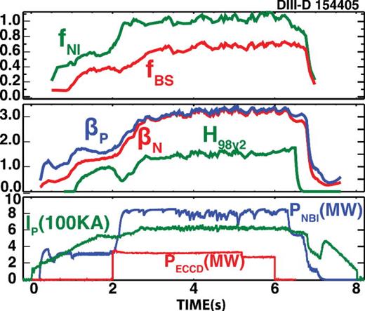
Experimental Advanced Superconducting Tokamak (EAST) is a fully superconducting tokamak with an ITER-like divertor configurations, positioned to give key demonstrations of 100 s H-mode discharges. Discharges in high confinement over 30 s have been demonstrated.22 Significant upgrades, including heating and current drive power of over 20 MW, Resonant Magnetic Perturbations (RMP) coils, and a tungsten divertor, have been implemented in order to further extend these results to the first demonstration of long-pulse steady-state H-mode with reactor relevant boundary conditions. The interest motivated the joint experiments on DIII-D aiming at the development of a fully noninductive high performance plasma scenario with EAST-similar plasma cross section shape (i.e., upper biased double-null divertor shape with elongation κ ∼ 1.86 and average triangularity δ ∼ 0.6), plasma current formation consistent with the superconductive coils on EAST (i.e., ∼0.25 mA/s plasma ramp-up rate), and values of plasma current (i.e., ∼600 kA), toroidal field (i.e., ∼2.0 T),and heating power consistent with the new EAST capabilities (i.e., ∼11 MW). By building on earlier high experiments,23 the first joint experiments conducted on DIII-D have achieved and sustained a fully noninductive scenario at the high bootstrap current fraction about ∼5 s with a large radius ITB under the EAST-similar condition, as shown in Figure 1. In Figure 1, are the ratios of inductive and bootstrap current to the total plasma current (Ip), respectively. and are the heating powers by neutral beam injection (NBI) and electron cyclotron current drive (ECCD), respectively. is the confinement enhancement factor over the H-mode confinement scaling. The experiments increase the confidence in the potential of the high bootstrap fraction approach for application to steady state fusion reactor.
This paper discusses the progress toward steady-state tokamak operation exploiting the high bootstrap current fraction regime. In Sec. II, we show our improved understanding of the scenario stability, and based on that, very high values of βp and βN have been achieved in the presence of the strong internal transport barriers (ITB). In Sec. III, exploration of lower torque discharges with good confinement is shown. We also discuss the challenges for transport modeling of high βp plasmas. In Sec. IV, the efforts of extending the results to long pulse on EAST to demonstrate the steady state operation for fusion reactor are given.
II. IMPROVED UNDERSTANDING OF SCENARIO STABILITY LEADS TO ACHIEVEMENT OF VERY HIGH VALUES OF βp AND βN DESPITE STRONG ITB
The previous efforts by Politzer et al.23 for the development of high performance stationary high bootstrap fraction plasmas in DIII-D have shown that “relaxation oscillations” would limit the achievable current and pressure. These relaxation oscillations were attributed to growth and collapse of an internal transport barrier at .23 Utilizing new DIII-D capabilities and diagnostics with high time and spatial resolutions, the recent joint experiments have shown instead that the ITB is usually maintained during these oscillations, and that the repetitive drops in the stored energy come from collapses of the edge pedestal driven by an n = 1 ideal MHD external kink mode.24
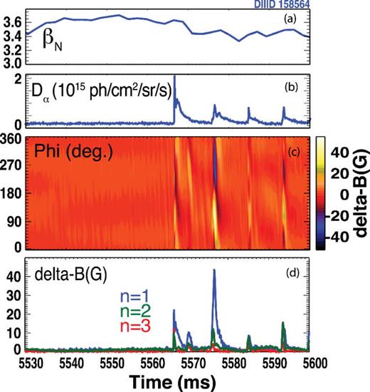
As discussed in Ref. 24, the relaxation oscillations have strong impact on , commonly observed in these high discharges. Figure 2 shows the typical behavior of the relaxation oscillation on for discharge 158564. The magnitude and toroidal structure of perturbed magnetic field clearly indicate that the stored energy drop is caused by bursts of n = 1 mode.
FIG. 2.
Time evolution of (a) ; (b) light; (c) contour plot of the perturbed poloidal magnetic field versus time and toroidal angle; (d) n = 1, 2, and 3 components of the perturbed magnetic field at the outer midplane.
It is important to note that accurate equilibrium reconstructions are needed in order to carry out reliable stability studies. These high βp discharges presented unique challenges for the equilibrium reconstructions. On DIII-D, the calculated edge current density with the Sauter bootstrap model is normally used to constrain the equilibrium reconstruction because of a lack of detailed edge current measurements. During the equilibrium reconstructions of these high plasmas, magnetic measurements were found to be very sensitive to the large edge bootstrap current while much less sensitive in low plasmas. Detailed analysis indicated that the magnetic measurements can be used to discriminate between the different bootstrap current models in high plasmas.25 It was shown that the Sauter model26 overestimates the edge bootstrap current in high , high collisionality plasmas; conversely, the first principle kinetic NEO27 model yields close agreement with the magnetics.
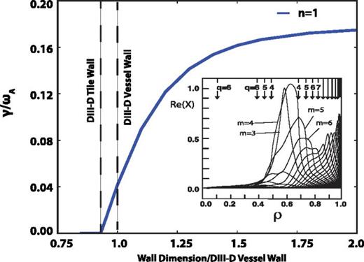
With the improved equilibrium reconstruction, we scan the wall distance to test the effect of plasma-wall distance on stability using the ideal stability code GATO,28 as shown in Figure 3. The plasma is found to be marginally stable with the ideal wall at the position of DIII-D vessel. The mode structure shows that, despite large internal components, the mode can be stabilized by a sufficiently close conducting wall.
FIG. 3.
Relationship between calculated growth rate of the n = 1 ideal kink mode normalized to the Alfven frequency and the ideal wall radius multiplier relative to the DIII-D vessel wall for discharge 158564 at t = 5.53 s (multiplier = 1 indicates an ideal wall at the position of DIII-D vessel). Inset shows the mode structure for the ideal wall far away from the plasma. The plasma surface is located at ∼0.74 on the horizontal axis, corresponding to an outer gap (as defined in the text) of 12 cm.
Close modal
The above findings further strengthen the understanding of relaxation oscillation discussed in Ref. 24 and also suggest that we can increase the ideal wall limit by reducing the plasma wall distance. But a large distance is usually needed to avoid wall overheating by large fast ion losses. As pointed out in Ref. 20, fast ion transport is a critical issue for advanced tokamak scenario development using the neutral beam injection current drive. At relatively low plasma current and large neutral beam injection (NBI) power, the compound losses from classical (due to large orbits) and anomalous [due to Alfvén eigenmodes (AEs) and possibly other instabilities] effects can be significant and can lead to overheating and damage of the limiter tiles. However, recent detailed analysis21 has shown that the anomalous fast ion losses are high mostly during the and density ramp-up phase. Higher density means shorter fast ion slowing down time and lower fast ion pressure gradient, thus reducing the drive for Alfvénic modes. It is worthwhile to point out that raising the pedestal density is particularly effective at slowing down the fast ions due to higher collisionality.
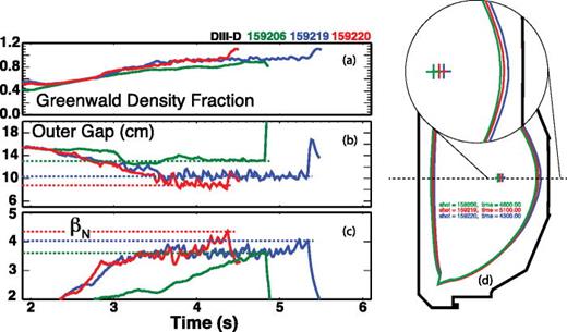
The above understanding has offered the possibility of developing an optimized waveform of the outer gap that could increase the ideal-wall limit without leading to unacceptable levels of wall over-heating by fast ion losses. Here, the “outer gap” is the distance between the plasma surface and the limiter surface, and it is the parameter controlled in the experiment. Note that the vessel wall is at an additional 8.5 cm larger radius than the limiter surface. Combining smaller outer gap and high density successfully enables higher beta in the experiment as shown in Figure 4. From Figure 4(b), we can see that the outer gap is normally around 15 cm. While reducing the gap to about 10 cm, higher beta has been successfully achieved. The minor radius of DIII-D is about 60 cm, and the ratio of the outer gap to the plasma minor radius is about 0.17–0.25. It is important to note that the plasma shape is kept similar when the outer gap is reduced as shown in Figure 4(d).
FIG. 4.
Time traces of Greenwald density fraction (a), plasma-limiter outer gap (b), and (c) for discharges 159206, 159219, and 159220; plasma shape is kept nearly the same as the plasma-limiter outer gap is reduced (d).
In discharge 159206, reaches about 3.6, i.e., about 5 times the internal inductance li, at t ∼ 4830 ms when the plasma disrupts due to a rapidly growing instability. As discussed in Ref. 24, the instability is consistent with an n = 1 kink mode occurring at the ideal MHD stability limit, and the experimentally observed growth time is consistent with an ideal kink mode slowly driven through the ideal-wall limit.29
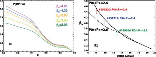
Reducing the plasma-limiter outer gap (and thus the plasma-wall distance) yields strong coupling between the ideal kink mode and the wall, leading to steady operation at higher . The ideal MHD stability code GATO allows us to vary the minor radius of the ideal wall, to test the effect of the plasma-wall distance on the instability. Based on a kinetic equilibrium from a DIII-D discharge, is increased artificially while keeping the plasma current constant at the same pressure peaking factor, as shown in Figure 5(a). A series of equilibria with increasing and almost fixed plasma safety factor profile is then obtained. For each equilibrium, stability analysis for n = 1 mode is carried out with a different minor radius of the ideal wall to investigate the relationship between the achievable and the plasma wall distance. The measured maximum agrees with the ideal wall limit prediction by GATO as shown in Figure 5(b). In Figure 5(b), the black solid line is the ideal wall limit prediction based on a kinetic equilibrium with the pressure peaking factor P0/ = 2.4. The experimental maximum is plotted in color bars with labels indicating the discharge and its corresponding pressure peaking factor. Experimentally, we noticed a slight reduction in the pressure peaking factor (i.e., from 2.5 to 2.4) with the reduction in the outer gap as shown in Figure 5(b). As pointed out in Ref. 30, broadening the pressure leads to improvements in the ideal wall limit. This small difference causes a big effect in the ideal wall limit prediction, especially at smaller outer gap, as can be seen from the black dashed line which shows the ideal wall limit prediction based on a kinetic equilibrium with the pressure peaking factor P0/ = 2.6.
FIG. 5.
(a) Scaled pressure profiles with increasing ; (b) the measured maximum in DIII-D agrees with the ideal wall limit prediction by GATO. The black solid line shows the prediction based on a kinetic equilibrium with the pressure peaking factor P0/ = 2.4. The experimental maximum is plotted in color bars with labels indicating the discharge and its corresponding pressure peaking factor. The black dashed line shows the prediction based on a kinetic equilibrium with the pressure peaking factor P0/ = 2.6.
Close modal
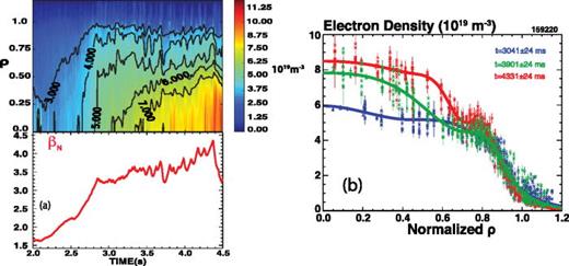
During the joint experiments, it was observed that the radius of the ITB expands with increasing as shown in Figure 6(a). With increasing , the foot of the ITB expands to a larger minor radius, as can also be seen from the density profiles at three time windows (24 ms) shown in Figure 6(b). Larger minor radius of the ITB foot improves wall-stabilization of the external kink mode, thus enabling higher if a conducting wall is sufficiently close to the plasma. It is worthwhile to point out that high values of and (∼4) have been sustained for several (≥5) energy confinement times with large radius ITBs (in ion and electron profiles) and close conducting wall, as shown in Ref. 24.
FIG. 6.
(a) Contour plot of electron density versus ρ and time (upper) and time trace of (bottom) and (b) electron density profile at three time intervals.
III. GOOD CONFINEMENT ACHIEVED AT REDUCED ROTATION
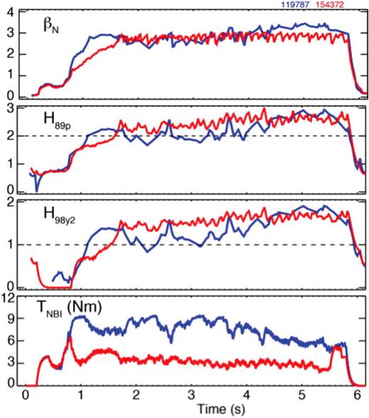
EAST has two NBI beam lines in the balanced injection configuration, providing maximum toroidal torque of ∼3 Nm.31 This motivates a related investigation on DIII-D to extend previous high torque studies (∼7 Nm)23 to low torque (∼3 Nm) studies similar with EAST. The new experiments reproduced excellent confinement similar to that achieved in the 2004 experiments (∼7 Nm) as shown in Figure 7.23 Figure 7 shows the time histories of several plasma parameters of high torque discharge 119787 with NBI torque about 7 Nm and low torque discharge 154372 with NBI torque about 3 Nm with counter neutral beam sources applied.
FIG. 7.
Time histories of several plasma parameters of high torque discharge 119787 and low torque discharge 154372.
At even lower torque (∼1.1 Nm) noninductive high plasmas, good normalized confinement has been obtained. In Figure 8(a), the profiles of the toroidal rotation with different torque (∼4.8 Nm for 163791 and ∼1.1 Nm for 163552) are shown. The experimental results indicate that the neoclassical thermal transport dominates the ion channel, while anomalously high thermal transport dominates the electron channel. However, as shown in Figure 8(b), reducing toroidal rotation causes little turbulence change in these high plasmas. In both higher and lower rotation discharges, our fluctuation diagnostics find no measurable low-k turbulence, in the range of frequency and fluctuation magnitude where low-k turbulence is generally observed.
FIG. 8.
(a) Toroidal rotation profiles and (b) spectra of density fluctuations for low and high torques at ρ = 0.6. The frequency range where low-k turbulence is generally observed is f > 100 kHz (fluctuation peaks around 50 kHz are associated with low level Alfvén eigenmode activity having little effect on thermal transport with H98y2 ∼ 1.48 for 163791 and H98y2 ∼ 1.46 for 163552).
Close modal
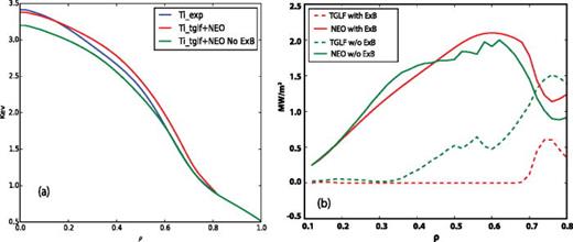
To explain the curious results shown above, energy transport modeling with quasi-linear turbulent transport code TGLF32 for turbulent transport and neoclassical and classical collision transport with NEO has been carried out for high torque discharge #154406. Modeling where only the ion temperature is evolved (with self-consistent ion-electron exchange terms) shows less sensitivity on toroidal rotation, and the predicted ion temperature agrees well with the experimental value with or without ExB shear as shown in Figure 9(a). From the ion energy fluxes predicted by TGLF and NEO as shown in Figure 9(b), it can be seen that the neoclassical transport dominates the ion thermal transport.
FIG. 9.
(a) Predicted ion temperature with ExB shear (red) and without ExB shear (green) agrees well with experimental value (blue); (b) predicted ion energy fluxes with and without ExB shear show that neoclassical transport dominates the ion thermal transport.
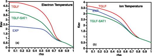
However, if we evolve electron and ion temperatures together, TGLF can dramatically underpredict the electron transport as shown in Figure 10(a). The predicted electron temperature (the red line) is much larger than the experimental value (the blue line). Recent nonlinear multi-scale analysis shows that when the ion temperature gradient (ITG) mode is reduced, the zonal flow is also reduced, thus allowing the electron temperature gradient (ETG) mode to grow stronger.33 A new model, named TGLF-SAT1,34 for the saturated turbulence intensity spectrum based on the multi-scale GYRO simulations has been developed. It includes zonal flow regulation of multi-scale turbulence in TGLF and improves the transport prediction as can be seen in Figure 10(a). Figure 10(b) shows the comparison of predicted ion temperature profiles from TGLF and TGLF-SAT1 with the experimental value. It is necessary to mention that though the new model TGLF-SAT1 improves the transport prediction, the model is still under development.
FIG. 10.
(a) Comparison of predicted electron temperature by TGLF (red) and TGLF-SAT1 (green) with the experimental value (blue). (b) Comparison of predicted ion temperature by TGLF (red) and TGLF-SAT1 (green) with the experimental value (blue).
IV. EXTENDING RESULTS TO LONG PULSE STEADY STATE ON EAST WILL DEMONSTRATE STEADY STATE OPERATION FOR FUSION REACTOR
The goal of the joint experiments carried out on DIII-D is to extend the integrated high performance results to long pulse steady state on EAST. Due to the limitation of device capabilities, DIII-D can only run discharges of order 10 s. However, the joint experiments on DIII-D24,35 with EAST-similar operational conditions can provide the physics basis for long pulse scenario on EAST. Based on studies on DIII-D, high performance plasmas are being extended to long pulse steady-state operations on EAST.
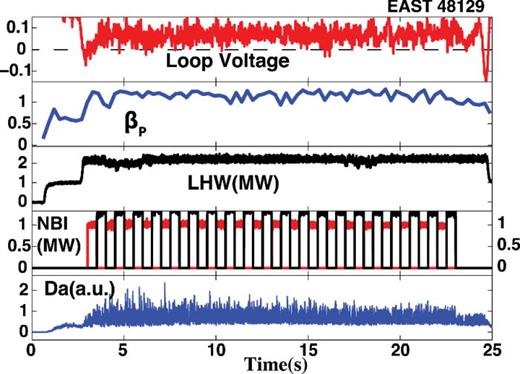
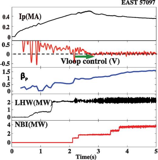
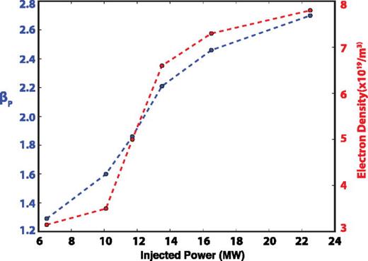
Figure 11 shows a 25 s H-mode discharge with lower hybrid wave (LHW) and NBI heating obtained on EAST in 2014. As can be seen from the time trace of the loop voltage, the discharge is not fully noninductive. An algorithm for loop voltage control has successfully been developed and deployed in the EAST plasma control system. In Figure 12, we can clearly see that the loop voltage has been controlled to be about zero using the LHW and NBI heating. is not high (∼1.5) due to insufficient power injection. If we assume that H98y2 = 1.3 and total noninductive current is about 500 kA, 0D modeling analysis indicates higher , and fully noninductive operation can be expected with more injected power as shown in Figure 13. Thus, with more power injection, EAST will have the ability to carry out the long pulse steady state exploration. In Table I, we list the injected power in discharge 57097 and the available power (including electron cyclotron heating (ECH), Ion Cyclotron Heating (ICH), lower hybrid heating (LH), and neutral beam injection (NBI)) for the next campaign in 2016.
FIG. 11.
Time traces of several plasma parameters for EAST 25 s H-mode discharge 48129 with Ip ∼ 300 kA, Bt ∼ 2.3 T, and q95 ∼ 7.8.
FIG. 12.
Time traces of several plasma parameters for EAST fully noninductive discharge 57097 with loop voltage control algorithm applied (Ip ∼ 350 kA, Bt ∼ 2.7 T and q95 ∼ 8).
FIG. 13.
0D modeling analysis shows expected higher fully noninductive operation with more injected power with assumed H98y2 = 1.3, total noninductive current about 500 kA, and Bt ∼ 2.7 T.
TABLE I.
Auxiliary heating capability of EAST for discharge 57097 and the next campaign in 2016.
| #57097 | 2016 | |
|---|---|---|
| PECH (MW) | 0 | 1–3 |
| PICH (MW) | 0 | 3–6 |
| PNBI (MW) | 4 | 5–8 |
| PLH (MW) | 2.1 | 3–5.5 |
| PTOT (MW) | 6.1 | 12–22.5 |
| #57097 | 2016 | |
|---|---|---|
| PECH (MW) | 0 | 1–3 |
| PICH (MW) | 0 | 3–6 |
| PNBI (MW) | 4 | 5–8 |
| PLH (MW) | 2.1 | 3–5.5 |
| PTOT (MW) | 6.1 | 12–22.5 |
V. SUMMARY
In summary, joint experiments carried out both at DIII-D and EAST have advanced the development of high bootstrap current scenario toward an attractive fusion reactor scenario.
An improved understanding of the scenario stability leads to the achievement of very high values of and in concert with strong ITBs. Combining high density and small plasma wall outer distance enables higher β. The measured maximum agrees well with the ideal wall limit prediction. High values of sustained and have been achieved with large radius ITB and close conducting wall. Good confinement has been achieved at reduced toroidal rotation. These experiments challenge the present understanding of energy transport. A new turbulent transport model, named TGLF-SAT1, has been developed including zonal flow regulation of multi-scale turbulence in TGLF and proved to improve the transport prediction. Though the transport prediction improves, this is still under development. Based on the physics basis developed on DIII-D, these high experimental results are being extended on EAST toward long pulse steady state operation.
ACKNOWLEDGMENTS
This paper was supported in part by the National Magnetic Confinement Fusion Program of China (Nos. 2015GB110001 and 2015GB102000) and the U.S. Department of Energy under DE-FC02-04ER54698, DE-AC52-07NA27344, DE-FG02-08ER54999, DE-AC02-09CH11466, DE-FG02-07ER54917, and DE-FG02-06ER54871. DIII-D data shown in this paper can be obtained in digital format by following the links in Ref. 36.
References
1.
T.
Luce
,Phys. Plasmas
18
,
030501
(
2011
).
2.
M.
Kikuchi
andM.
Azumi
,Rev. Mod. Phys.
84
,
1807
(
2012
).
3.
T.
Oikawa
,Y.
Kamada
,A.
Isayama
,T.
Fujita
,T.
Suzuki
,N.
Umeda
,M.
Kawai
,M.
Kuriyama
,L. R.
Grishama
,Y.
Ikeda
et al,Nucl. Fusion
41
,
1575
(
2001
).
4.
S.
Shiraiwa
,G.
Baek
,P. T.
Bonoli
,I. C.
Faust
,A. E.
Hubbard
,O.
Meneghini
,R. R.
Parker
,G. M.
Wallace
,J. R.
Wilson
,R. W.
Harvey
et al,Nucl. Fusion
53
,
113028
(
2013
).
5.
R.
Prater
,Phys. Plasmas
11
,
2349
(
2004
).
6.
G.
Gormezaon
,A. C. C.
Sips
,T. C.
Luce
,S.
Ide
,A.
Becoulet
,X.
Litaudon
,A.
Isayama
,J.
Hobirk
,M. R.
Wade
,T.
Oikawa
et al,Nucl. Fusion
47
,
S285
(
2007
).
7.
R. C.
Wolf
,Plasma Phys. Controlled Fusion
45
,
R1
(
2003
).
8.
J. W.
Connor
,T.
Fukuda
,X.
Garbet
,C.
Gormezano
,V.
Mukhovatov
,M.
Wakatani
,the ITB Database Group
, and
the ITPA Topical Group on Transport and Internal Barrier Physics
,
Nucl. Fusion
44
,
R1
(
2004
).
9.
A. M.
Garofalo
,M. A.
Adboud
,J. M.
Cankie
,V. S.
Chan
,A. W.
Hyatta
,D. N.
Hill
,N. B.
Morley
,G. A.
Navratile
,M. E.
Sawanf
,T. S.
Taylor
et al,Fusion Eng. Des.
89
,
876
(
2014
).
10.
S. P.
Gerhardt
,D. S.
Darrow
,R. E.
Bell
,B. P.
LeBlanc
,J. E.
Menard
,D.
Mueller
,A. L.
Roquemore
,S. A.
Sabbagh
, andH.
Yuh
,Nucl. Fusion
53
,
063021
(
2013
).
11.
M.
Kikuchi
,Nucl. Fusion
30
,
265
(
1990
).
12.
M.
Kikuchi
, inProceedings of the 15th International Conference on Plasma Physics and Controlled Nuclear Fusion Research (Seville)
(
IAEA
,
Vienna
,
1995
), Vol. 1, p.
31
.
13.
M.
Hugon
,B. Ph.
van Milligen
,P.
Smeulders
,L. C.
Appel
,D. V.
Bartlett
,D.
Boucher
,A. W.
Edwards
,L.-G.
Eriksson
,C. W.
Gowers
,T. C.
Hender
et al,Nucl. Fusion
32
,
33
(
1992
).
14.
F.
Levinton
,M. C.
Zarnstorff
,S. H.
Batha
,M.
Bell
,R. E.
Bell
,R. V.
Budny
,C.
Bush
,Z.
Chang
,E.
Fredrickson
,A.
Janos
et al,Phys. Rev. Lett.
75
,
4417
(
1995
).
15.
M.
Kikuchi
,Plasma Phys. Controlled Fusion
35
,
B39
(
1993
).
16.
T.
Ozeki
,M.
Azumi
,T.
Tsunematsu
,K.
Tani
,M.
Yagi
, andS.
Tokuda
, inProceedings of the 14th International Conference on Plasma Physics and Controlled Nuclear Fusion Research (Wurzburg)
(
IAEA
,
Vienna
,
1993
), Vol. 2, p.
187
.
17.
A.
Sips
,R.
Arslanbekov
,C.
Atanasiu
,W.
Becker
,G.
Becker
,K.
Behler
,K.
Behringer
,A.
Bergmann
,R.
Bilato
,D.
Bolshukhin
,K.
Borrass
et al,Plasma Phys. Controlled Fusion
44
,
B69
(
2002
).
18.
T.
Fujita
,S.
Ide
,H.
Shirai
,M.
Kikuchi
,O.
Naito
,Y.
Koide
,S.
Takeji
,H.
Kubo
, andS.
Ishida
,Phys. Rev. Lett.
78
,
2377
(
1997
).
19.
X.
Litaudon
,R.
Arslanbekov
,G. T.
Hoang
,E.
Joffrin
,F.
Kazarian-Vibert
,D.
Moreau
,Y.
Peyssondag
,P.
Bibet
,P.
Froissard
,M.
Goniche
,G.
Rey
et al,Plasma Phys. Controlled Fusion
38
,
1603
(
1996
).
20.
W. W.
Heidbrink
,J. R.
Ferron
,C. T.
Holcomb
,M. A.
Van Zeeland
,X.
Chen
,C. M.
Collins
,A. M.
Garofalo
,X.
Gong
,B. A.
Grierson
,M.
Podestà
et al,Plasma Phys. Controlled Fusion
56
,
095030
(
2014
).
21.
C. T.
Holcomb
,W. W.
Heidbrink
,J. R.
Ferron
,M. A.
Van Zeeland
,A. M.
Garofalo
,W. M.
Solomon
,X.
Gong
,D.
Mueller
,B.
Grierson
,E. M.
Bass
et al,Phys. Plasmas
22
,
055904
(
2015
).
22.
J.
Li
,H. Y.
Guo
,B. N.
Wan
,X. Z.
Gong
,Y. F.
Liang
,G. S.
Xu
,K. F.
Gan
,J. S.
Hu
,H. Q.
Wang
,L.
Wang
et al,Nat. Phys.
9
,
817
(
2013
).
23.
P. A.
Politzer
,A. W.
Hyatt
,T. C.
Luce
,F. W.
Perkins
,R.
Prater
,A. D.
Turnbull
,D. P.
Brennan
,J. R.
Ferron
,C. M.
Greenfield
,J.
Jayakumar
et al,Nucl. Fusion
45
,
417
(
2005
).
24.
A. M.
Garofalo
,X.
Gong
,B. A.
Grierson
,Q.
Ren
,W. M.
Solomon
,E. J.
Strait
,M. A.
Van Zeeland
,C. T.
Holcomb
et al,Nucl. Fusion
55
,
123025
(
2015
).
25.
Q.
Ren
,L. L.
Lao
,A. M.
Garofalo
,C. T.
Holcomb
,W. M.
Solomon
,E. A.
Belli
,S. P.
Smith
,O.
Meneghini
,J.
Qian
,G.
Li
et al,Plasma Phys. Controlled Fusion
57
,
025020
(
2015
).
26.
O.
Sauter
,C.
Angioni
, andY. R.
Lin-Liu
,Phys. Plasmas
9
,
5140
(
2002
).
27.
E. A.
Belli
andJ.
Candy
,Plasma Phys. Controlled Fusion
54
,
015015
(
2012
).
28.
L. C.
Bernard
,F. J.
Helton
, andR. W.
Moore
,Comput. Phys. Commun.
24
,
377
(
1981
).
29.
J. D.
Callen
,C. C.
Hegna
,B. W.
Rice
,E. J.
Strait
, andA. D.
Turnbull
,Phys. Plasmas
6
,
2963
(
1999
).
30.
A. D.
Turnbull
,T. S.
Taylor
,M. S.
Chu
,R. L.
Miller
, andY. R.
Lin-Liu
,Nucl. Fusion
38
,
1467
(
1998
).
31.
B. N.
Wan
,J.
Li
,H.
Guo
,Y.
Liang
,G.
Xu
,X.
Gong
, andA. M.
Garofalo
, inOV/3-3, 25th Fusion Energy Conference (FEC)
(
2014
).
32.
G. M.
Staebler
,J. E.
Kinsey
, andR. E.
Waltz
,Phys. Plasmas
14
,
055909
(
2007
).
35.
X.
Gong
,A. M.
Garofalo
,B.
Wan
,J.
Li
,J.
Qian
,Q.
Ren
,S.
Ding
,C. T.
Holcomb
,W. M.
Solomon
,A.
Hyatt
et al, “Development of fully noninductive scenario at high bootstrap current fraction for steady state tokamak operation on EAST and DIII-D,”Nucl. Fusion
(submitted).
© 2016 Author(s).
2016
Author(s)




No comments:
Post a Comment