[2405.10540] Radar Positioning for Accurate Sensing of Pulse Waves at Multiple Sites Using a 3D Human Model
Electrical Engineering and Systems Science > Signal Processing
This study proposes a sensing method using a millimeter-wave array radar and a depth camera to measure pulse waves at multiple sites on the human body. Using a three-dimensional shape model of the target human body measured by the depth camera, the method identifies reflection sites on the body through electromagnetic scattering simulation. On the basis of the simulation, the radar system can be positioned at a suitable location for measuring pulse waves depending on the posture of the target person.
Through measurements using radar and depth camera systems, we demonstrate that the proposed method can estimate the body displacement waveform caused by pulse waves accurately, improving the accuracy by 14% compared with a conventional approach without a depth camera. The proposed method can be a key to realizing an accurate and noncontact sensor for monitoring blood pressure.
Submission history
From: Takuya Sakamoto [view email][v1] Fri, 17 May 2024 04:57:46 UTC (13,830 KB)
Summary
This paper proposes a novel method for accurately measuring pulse waves at multiple body sites using a millimeter-wave radar system and a depth camera. The key points are:
- A 3D human body model is obtained using a depth camera to identify reflection sites on the body through electromagnetic scattering simulation.
- The radar system can be optimally positioned based on the simulation to measure pulse waves accurately depending on the person's posture.
- Experiments with two participants demonstrate the proposed method improves pulse wave estimation accuracy by 14% compared to a conventional approach without using a depth camera.
- The radar estimates body displacement waveforms caused by pulse waves, which are compared against laser sensor references.
- An array radar with beamforming is used to measure displacements at multiple body sites simultaneously.
- Software was developed to visualize reflection sites on the 3D body model and guide optimal radar positioning.
In summary, the depth camera enables intelligent positioning of the radar to maximize pulse wave signal quality based on the individual's body shape and posture. This allows accurate, multi-site, non-contact monitoring of pulse waves, which could enable convenient blood pressure tracking in the future.
Authors
The authors of this paper are Takehito Koshisaka and Takuya Sakamoto, both associated with the Department of Electrical Engineering, Graduate School of Engineering, Kyoto University, Kyoto, Japan.
Takehito Koshisaka received his B.E. degree in electrical and electronic engineering from Kyoto University in 2021 and his M.E. degree in electrical engineering from the Graduate School of Engineering, Kyoto University, in 2023.
Takuya Sakamoto (Senior Member, IEEE) has a more extensive background:
- B.E. degree in electrical and electronic engineering from Kyoto University in 2000
- M.I. and Ph.D. degrees in communications and computer engineering from the Graduate School of Informatics, Kyoto University, in 2002 and 2005, respectively
- Assistant Professor at the Graduate School of Informatics, Kyoto University from 2006 to 2015
- Visiting Researcher at Delft University of Technology, Delft, the Netherlands from 2011 to 2013
- Associate Professor at the Graduate School of Engineering, University of Hyogo, Himeji, Japan from 2015 to 2019
- Visiting Scholar at University of Hawaii at Manoa, Honolulu, HI, USA in 2017
- Associate Professor at the Graduate School of Engineering, Kyoto University from 2019 to 2022
- PRESTO researcher of the Japan Science and Technology Agency, Japan from 2018 to 2022
- Professor at the Graduate School of Engineering, Kyoto University since 2022
Prof. Sakamoto's research interests include wireless human sensing, radar signal processing, and radar measurement of physiological signals. He has received numerous awards for his work, including several best paper and achievement awards from various conferences and societies.
The authors have referenced several prior works related to non-contact pulse wave measurement using radar, electromagnetic simulation with human body models, and the use of depth cameras in these contexts. However, the specific integration of a depth camera to guide optimal radar positioning for accurate multi-site pulse wave monitoring appears to be a novel contribution of this paper building upon the prior work in the field.
Artifacts
The paper does not mention any publicly available artifacts or datasets for independent verification of the results. The authors conducted experiments with two human participants and compared their radar-based pulse wave measurements against reference laser displacement sensors. However, they did not specify making the experimental data openly available.
To enable independent verification and reproducibility, it would be beneficial for the authors to publish:
1. The 3D human models obtained from the depth camera during the experiments
2. The raw radar data collected during the pulse wave measurements
3. The synchronized reference measurements from the laser displacement sensors
4. The software code used for electromagnetic scattering simulation, visualization, and pulse wave estimation from the radar data
Without access to these artifacts, it would be difficult for other researchers to exactly reproduce the results or directly compare their own methods against this work. The paper's findings would be strengthened by providing these resources and promoting open science practices.
However, given that the experiments involve human subjects and potentially identifiable biometric data, there may be ethical or legal constraints on releasing the full experimental data. In such cases, the authors should at least strive to make their data analysis and visualization code openly available, along with any non-sensitive or anonymized data that can be shared.
Clinical Application
The proposed system using millimeter-wave radar and a depth camera could potentially be suitable for certain clinical monitoring applications, particularly in measuring parameters related to cardiovascular health. However, further validation and refinement would likely be necessary before widespread clinical adoption.
The key parameters that could potentially be monitored using this system include:
- Pulse Wave Velocity (PWV): By measuring the arrival times of pulse waves at multiple body sites, the system could estimate PWV, which is an indicator of arterial stiffness and a predictor of cardiovascular risk.
- Blood Pressure: As mentioned in the paper, pulse transit time (PTT) derived from multi-site pulse wave measurements can be correlated with blood pressure. With proper calibration, this system could potentially enable continuous, non-invasive blood pressure monitoring.
- Heart Rate: The periodic waveforms detected by the radar system directly correspond to the heart rate, allowing for continuous heart rate monitoring without the need for contact sensors.
- Respiratory Rate: Although not the primary focus of this paper, radar-based systems have also been used to measure respiratory rate by detecting chest wall motion. This functionality could potentially be integrated into the proposed system.
However, before clinical adoption, the system would need to be rigorously validated against gold-standard clinical measurements in a diverse patient population. Factors such as different body types, ages, and health conditions may affect the system's accuracy and reliability.
Moreover, the system's suitability for continuous, long-term monitoring in real-world clinical settings would need to be assessed, considering factors such as patient comfort, mobility, and ease of use for healthcare providers.
Nonetheless, the proposed system represents a promising step towards non-invasive, contactless monitoring of vital cardiovascular parameters, which could have significant applications in telemedicine, home healthcare, and continuous monitoring of high-risk patients.
Pulse Wave Velocity (PWV)
Pulse Wave Velocity (PWV) is a measure of the speed at which a pressure wave propagates through the arterial system. It is widely recognized as a key indicator of arterial stiffness and a powerful predictor of cardiovascular risk.
In healthy arteries, the arterial walls are elastic, allowing them to expand and contract with each heartbeat. This elasticity helps to absorb the pressure wave and slow down its propagation. However, with age and certain cardiovascular risk factors (such as hypertension, diabetes, and obesity), the arterial walls can become stiffer, leading to faster propagation of the pressure wave.
PWV is typically measured by detecting the arrival of the pulse wave at two different sites along the arterial tree (such as the carotid and femoral arteries) and measuring the time delay between these two points. The distance between the two sites divided by the time delay gives the PWV.
In clinical practice, PWV is used for several purposes:
1. Risk Stratification: PWV is an independent predictor of cardiovascular morbidity and mortality. Patients with higher PWV values are at increased risk of heart attack, stroke, and other cardiovascular events. PWV can help identify high-risk patients who may benefit from more aggressive risk factor management.
2. Early Detection of Subclinical Organ Damage: Increased arterial stiffness can lead to damage in various organ systems, such as the heart, brain, and kidneys. PWV can detect this subclinical organ damage before overt clinical symptoms appear, allowing for earlier intervention.
3. Monitoring Treatment Effects: Interventions that reduce cardiovascular risk, such as lifestyle modifications, blood pressure control, and lipid-lowering therapy, can also improve arterial stiffness. PWV can be used to monitor the effectiveness of these interventions over time.
4. Research and Drug Development: PWV is often used as an endpoint in clinical trials of new cardiovascular drugs or interventions, as it provides a more sensitive and mechanistic measure of cardiovascular health compared to traditional risk factors alone.
Traditionally, PWV has been measured using dedicated devices that require skilled operators, such as applanation tonometry or oscillometric devices. The proposed radar-based system in this paper could potentially offer a more convenient, non-contact method for PWV assessment, which could facilitate its wider adoption in clinical practice and research.
However, as mentioned earlier, rigorous validation against established PWV measurement techniques would be necessary before this radar-based approach could be recommended for routine clinical use. Nonetheless, the potential for continuous, non-invasive PWV monitoring represents an exciting frontier in cardiovascular risk assessment and management.
Radar Positioning for Accurate Sensing of Pulse Waves at Multiple Sites Using a 3D Human Model
Takehito Koshisaka and Takuya Sakamoto Manuscript received April 16, 2023; revised May 31, 2024; accepted May 31, 2024. Date of publication May 31, 2024; date of current version May 31, 2024.This work was supported in part by JST under Grants JPMJCE1307 and JPMJMI22J2, by SECOM Science and Technology Foundation, and JSPS KAKENHI under Grants 19H02155, 21H03427, and 23H01420.T. Koshisaka and T. Sakamoto are with the Department of Electrical Engineering, Graduate School of Engineering, Kyoto University, Kyoto, Kyoto 615-8510, Japan (e-mail: sakamoto.takuya.8n@kyoto-u.ac.jp).
Abstract
This study proposes a sensing method using a millimeter-wave array radar and a depth camera to measure pulse waves at multiple sites on the human body. Using a three-dimensional shape model of the target human body measured by the depth camera, the method identifies reflection sites on the body through electromagnetic scattering simulation. On the basis of the simulation, the radar system can be positioned at a suitable location for measuring pulse waves depending on the posture of the target person. Through measurements using radar and depth camera systems, we demonstrate that the proposed method can estimate the body displacement waveform caused by pulse waves accurately, improving the accuracy by 14% compared with a conventional approach without a depth camera. The proposed method can be a key to realizing an accurate and noncontact sensor for monitoring blood pressure.
Index Terms:
Electromagnetic scattering, pulse wave, millimeter-wave radar, depth camera
I Introduction
Hypertension increases the risk of cardiovascular diseases [1], and the percentage of hypertensive patients aged 30–79 years was 33.1% in 2019 [2]. Because regular blood pressure measurement is necessary to keep blood pressure within an appropriate range [3], it is necessary to have a sensing system for constant monitoring of blood pressure.
Blood pressure is related to pulse transit time, which is calculated from the arrival time of pulse waves measured at multiple sites on the human body [4]. This has been achieved mostly using contact sensors [5, 6, 7]. Research on noncontact pulse wave measurement has been conducted intensively to make the system unobtrusive and easy to set up; the use of millimeter-wave radar systems has been reported for such purposes [14, 8, 9, 10, 11, 12, 13, 15]. For example, Oyamada et al. measured the body displacement waveform at the back and thigh simultaneously using a 79-GHz frequency-modulated continuous-wave (FMCW) radar system, and the accuracy was evaluated through simultaneous measurements with laser displacement sensors. To apply this technique in practice, we need to adjust the position of the radar system or the target person to receive echoes from the target sites on the body.
In this study, we propose a new approach for determining the position of the radar system depending on the target person’s position and posture using electromagnetic scattering simulation to estimate which part of the body the reflected waves are received from. We reduce the computational complexity using a simplified approximation instead of full-wave electromagnetic simulation. Some studies on electromagnetic simulations with a human body are also based on the physical optics (PO) approximation because of its simplicity and practicality [17, 18, 19, 20, 21, 22]. Some studies use geometrically simplified human models [23, 24], while other studies use precise human models obtained from a 3D laser scanner [25, 26, 27].
Konishi et al. reported electromagnetic wave scattering analysis with a human model obtained by a depth camera, assuming a radar frequency of 60 GHz, and visualized the reflection sites on the human body [28, 29]. Although the method proposed by Konishi et al. enables estimation of reflection sites on the human body surface, the method has not been applied to pulse wave measurement. In this study, we propose a method to achieve accurate pulse wave measurement without prior adjustment of the participant’s body posture by estimating the reflection sites on the target human body using electromagnetic wave scattering analysis to determine an appropriate radar position.
To obtain 3D human body shape data, Vahidpour and Sarabandi [27] used a 3D laser scanner to obtain a precise human model, which requires several cameras and a sufficiently large space. In this study, we use a depth camera to acquire a human model following the approach of Konishi et al. [28, 29]. Although some studies have used both a depth camera and a radar system [30, 31], they used the depth data only to estimate the position of the target person, whereas we consider the shape of the human body for radar measurement.
In this study, we propose a system to measure pulse waves at multiple locations with high accuracy by combining a depth camera and millimeter-wave radar. In Section II, we investigate the characteristics of millimeter-wave scattering from the human body surface by performing electromagnetic wave scattering analysis based on the PO approximation using a precise human model. In Section III, we propose a measurement system that integrates a depth camera and a millimeter-wave radar system, and evaluate its performance through experiments with two participants in the supine and prone positions.
II Electromagnetic Scattering Analysis and Estimation of Reflection Sites
II-A Electromagnetic Scattering Analysis with the PO Approximation
The PO approximation is used for electromagnetic wave scattering analysis. This approximation calculates the current distribution on the target surface caused by the incident magnetic field and the normal vector of the surface. If the target material is modeled as a perfect electric conductor, the current density at position on the target surface is approximated as
| (1) |
where is a unit normal vector, and is an incident magnetic field.
Assuming that the polarization directions of the transmitting and receiving elements are both in the -direction and the current density at each position is approximated by an infinitesimal dipole, the -component of the radiated electric field at antenna position is approximated as
| (2) |
where is a unit vector, is an imaginary unit, is the length of the dipole, is the impedance of free space, and is the wave number. Here we assume is sufficiently large compared with the reflection area.
Shijo et al.[32] proposed a PO-based method for visualizing high-frequency diffraction using a weighting function, called the eye function, defined as
| (3) |
where is the radius of the eye function and should be sufficiently larger than the wavelength [32]. Using (3), we can approximate the intensity of the electric field received from the vicinity of the scattering point as
| (4) |
where is the entire target boundary surface.
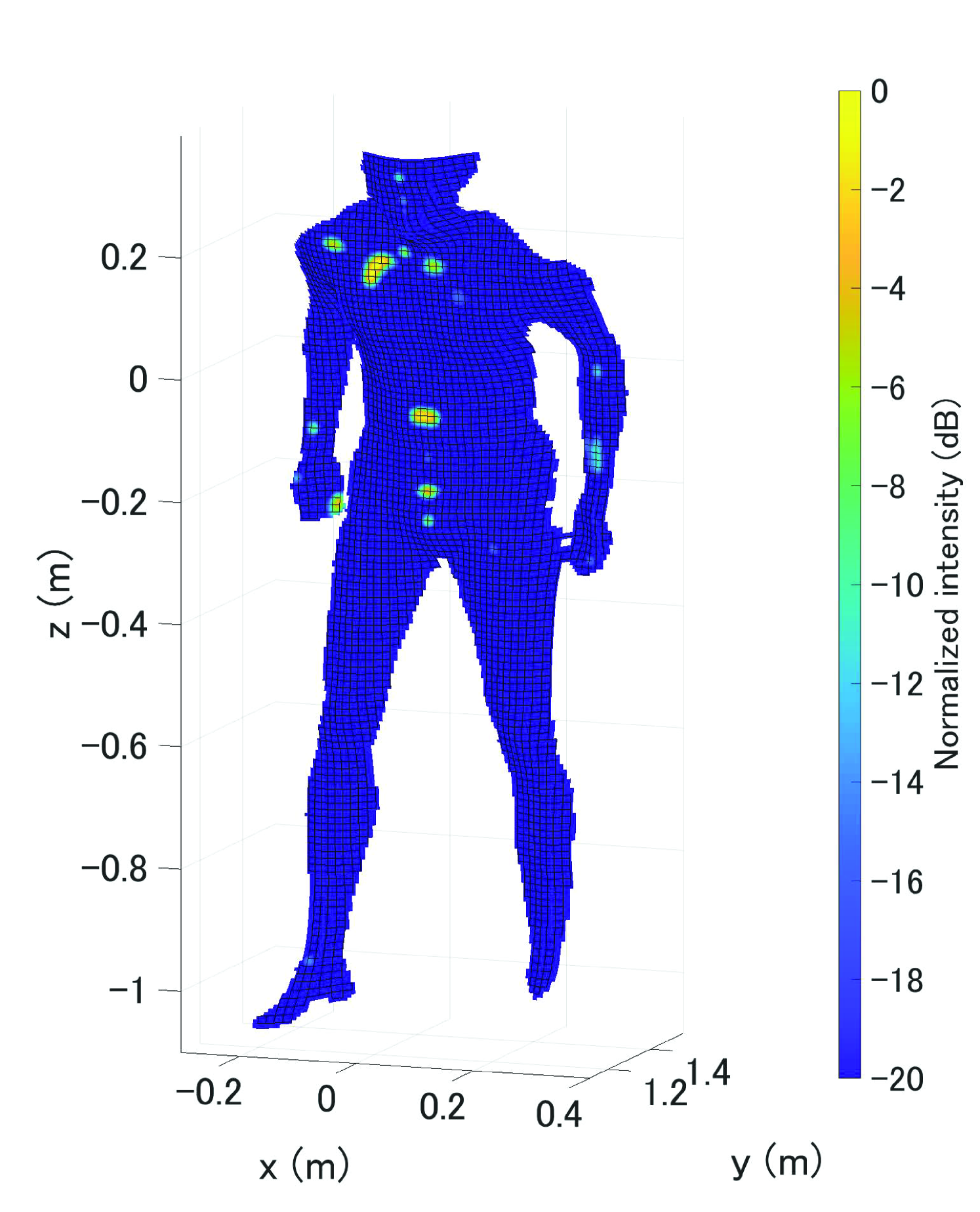
A human 3D model is obtained using an iReal 2E laser scanner (SCANTECH Co., Ltd., Hangzhou, China), whose parameters are given in Table I. Fig. 1 shows for the human model in a supine position, where we set and is the wavelength. In the figure, we see that reflection occurs mainly at several spots around the chest and abdomen. In addition, each area contributing reflection is small compared to the size of the human body.
II-B Simplified Method for Estimation of Reflection Spots
Because the calculation of using the PO approximation according to Eq. (4) contains a double integral over an area much larger than the wavelength, the computational cost can be unacceptably large in practice. To address this issue, we introduce an even simpler method as follows: Let be a radar antenna position and be a position on the target surface. We define
| (5) |
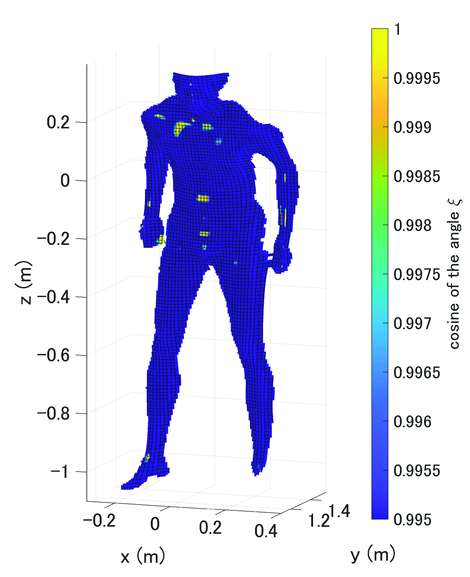
where is the angle between the radar line-of-sight direction and the normal vector . Note that satisfies .
If a point located at on the target surface has a large , the electric field scattered from the point is unlikely to contribute to the radar signal. Fig. 2 shows for a human model in a supine position with the same condition as in Fig. 1. Comparing this with Fig. 1, we see that is large close to the reflection area on the target surface, which indicates that can be used approximately to estimate the reflection areas instead of the PO approximation, and the computational cost in calculating is much smaller than that of PO-based calculation.
III Proposed Measurement System and Performance Evaluation
III-A Experimental Setup
In this study, we propose a method to determine an appropriate location of the radar system to obtain echoes from target sites on the human body. The method assumes a system with a millimeter-wave radar and depth camera installed over a target person lying in a prone position on a bed. We use an Intel RealSense D435 depth camera (Intel Corp., Santa Clara, California, U.S.) instead of the laser scanner used in the previous section. The parameters of the depth camera are given in Table II. Although the precision of a human model obtained with a depth camera is lower than that obtained with a laser scanner, a depth camera can acquire a human model in a shorter time and is suitable in practice.
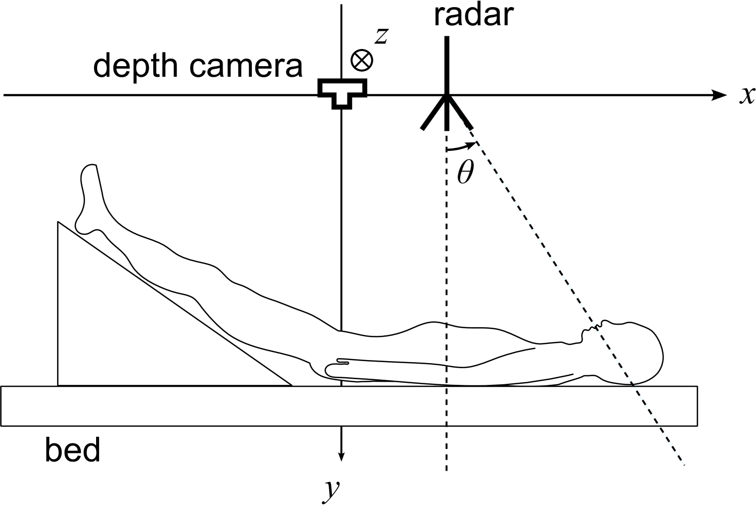
Fig. 3 shows a diagram of the proposed measurement system with a coordinate system with the -axis in the direction of the body axis and the -axis vertical to the floor. The depth camera is fixed at the top of the bed and set as the origin of the coordinate system. The millimeter-wave radar can scan along the -axis, where the -axis is 1.1 m from the bed top.
The measurement procedure using the proposed method is as follows:
-
1.
Obtain a human 3D model using a depth camera.
-
2.
Visualize the radiated power distribution.
-
3.
Locate the radar position to obtain echoes from the desired sites.
-
4.
Measure a body displacement waveform using the radar system.
In this study, we used a radar module (T14_01120112_2D, S-Takaya Electronics Industry, Okayama, Japan) that comprises a single-chip millimeter-wave sensor (IWR 1443, Texas Instruments Inc., Dallas, Texas, United States). The parameters of the radar module are given in Table III. We used a multiple-input and multiple-output (MIMO) array radar. If the distance to a target from the radar antennas is sufficiently greater than the antenna aperture size, the array can be approximated as a virtual array with elements, where and are the numbers of transmitting and receiving elements, respectively. The element spacing of the virtual array of the radar module was half the wavelength, and the angular resolution was approximately . We used laser displacement sensors (CDX-150, OPTEX FA Co., Ltd., Kyoto, Japan) as a reference for body displacement measurement. The parameters of the laser displacement sensors are shown in Table IV.
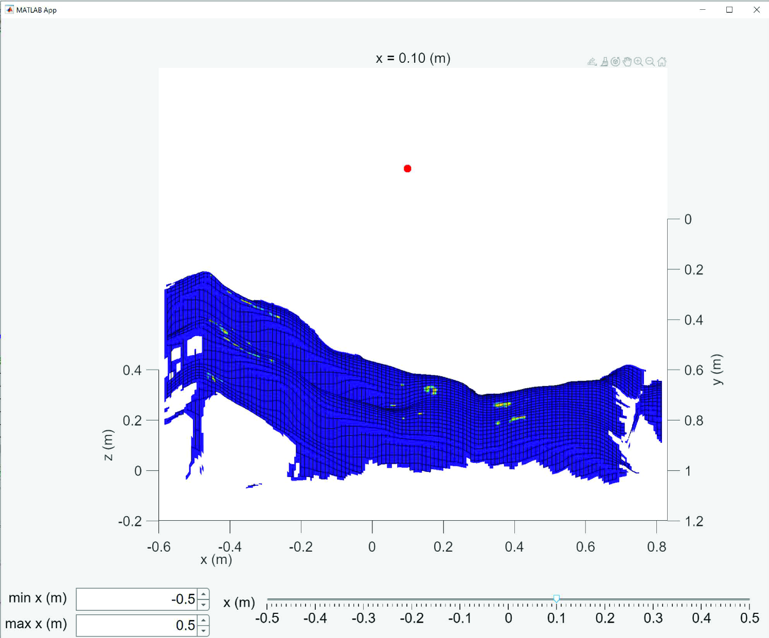
In this study, we developed software that displays an image of the human body with and indicates the intensity of the reflected electric field. With this software, the reflection sites on the body can be confirmed immediately when the radar position changes. The software runs on MATLAB as shown in Fig. 4, in which the image corresponds to calculated using the simplified method in Section II-B. The -coordinate of the radar position can be changed with the slider at the bottom of the screen. The radar position is expected to be optimized automatically if an appropriate objective function is defined. Despite this, the implementation of the optimization process is out of the scope of this study and will be an important topic to study in the future. In this study, we selected the radar position manually using this software.
III-B Array Radar Measurement of Pulse Waves
We propose a method for measuring a displacement waveform at multiple sites on the human body using a millimeter-wave radar system. Let us assume reflections points on the target human body, and let be the direction of arrival of the th echo with the corresponding displacement for . The th echo is phase-modulated by the body motion as . For simplicity, we assume hereafter.
For a radar system with a virtual array comprising elements with an element spacing of , the signal received from the th element is expressed as a function of range and slow time , where is a fast time. The received signal is then modeled as
| (6) |
where is a complex constant corresponding to the propagation path between the th target and th antenna element. Then, we define signal vector , which is used to estimate the th echo as using an appropriate weight vector for the th echo, where superscripted and represent a transpose operator and a complex-conjugate transpose operator, respectively. By selecting range for the th echo, we can estimate the displacement as .
To determine weight vector , we use a minimum variance distortionless response (MVDR) method, which is also called directionally constrained minimization of power (DCMP) [33]. Let be a steering vector for direction of arrival expressed as , where for an array with antenna spacing .
The MVDR (DCMP) weight vector is determined by
| (7) |
where is a correlation matrix of formulated as with the measurement time length .
For example, when measuring the displacements at two sites and on the target body, we used the MVDR weight vectors and to estimate the displacements and .
III-C Experimental Evaluation of the Proposed Method
We performed experiments using a depth camera, a millimeter-wave radar system, and a pair of laser displacement sensors with two participants lying on a bed in supine and prone positions. The measurement was performed six times for each participant. For three out of the six times, the position of the radar system was adjusted using the proposed method (case A), and for the other three times, the position was not adjusted (case B). The radar position in case B was shifted by m from the position in case A. The target sites on the body were selected to be the chest and the front of the thigh when the participants were in supine positions, and were selected to be the back and the back of the thigh when the participants were in prone positions. The radar and laser measurements were performed simultaneously for s while the participants were holding their breaths to prevent respiratory effects.
The accuracy of the proposed method is evaluated in terms of the correlation coefficient of the estimated and reference displacement waveforms and defined as
| (8) |
where and assuming for s.
We also evaluate the root-mean-square (RMS) error between and defined as
| (9) |
where is adjusted properly to compensate for the inclination of the laser displacement sensors. The range for the measurement and definition of slow time are also adjusted to compensate for the imperfect synchronization of the radar and laser data.
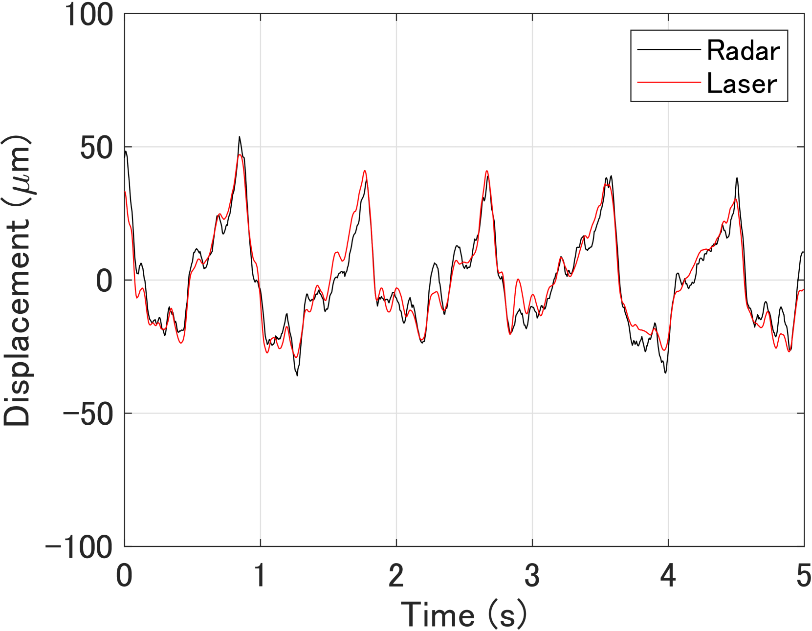
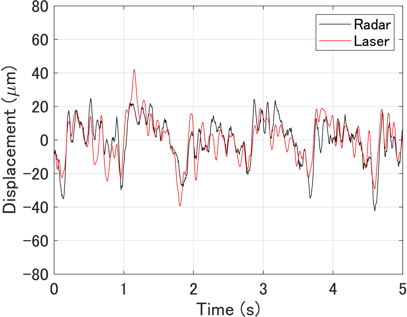
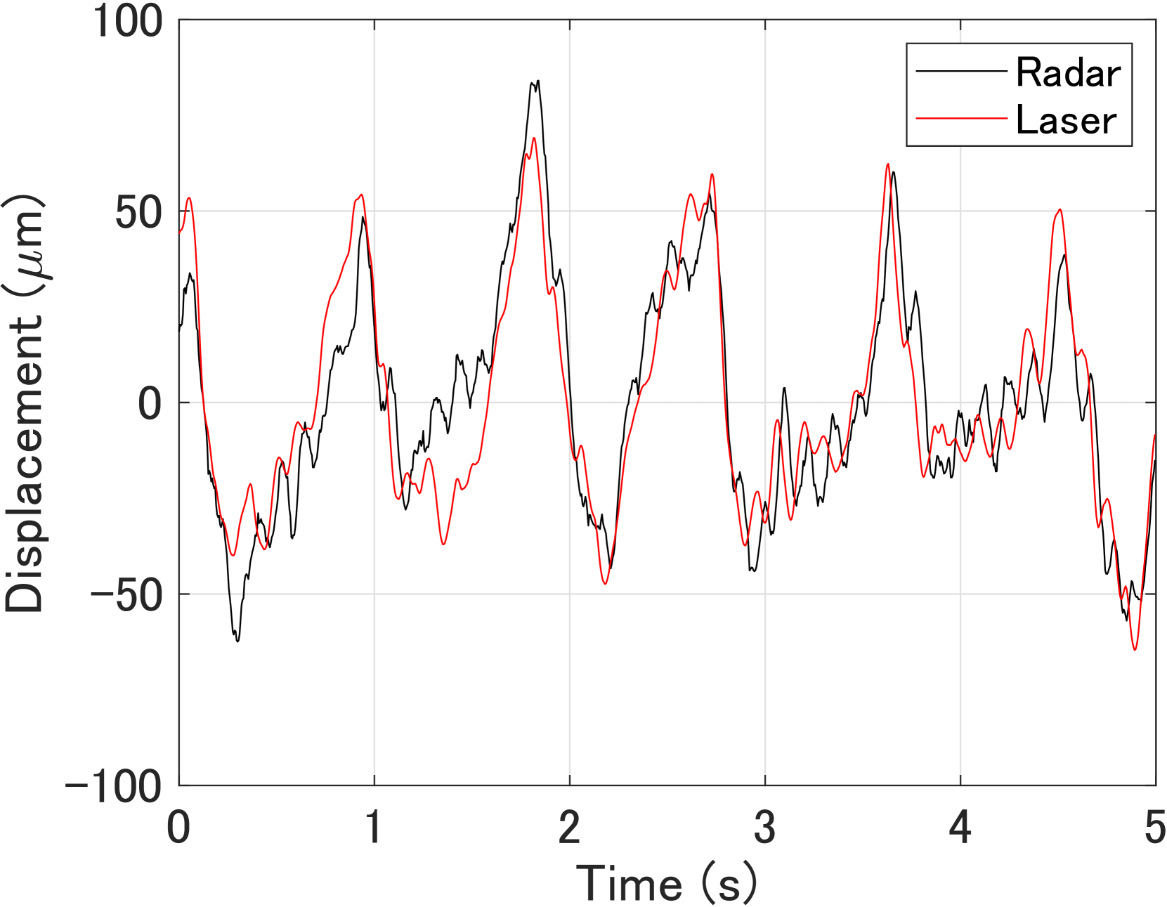
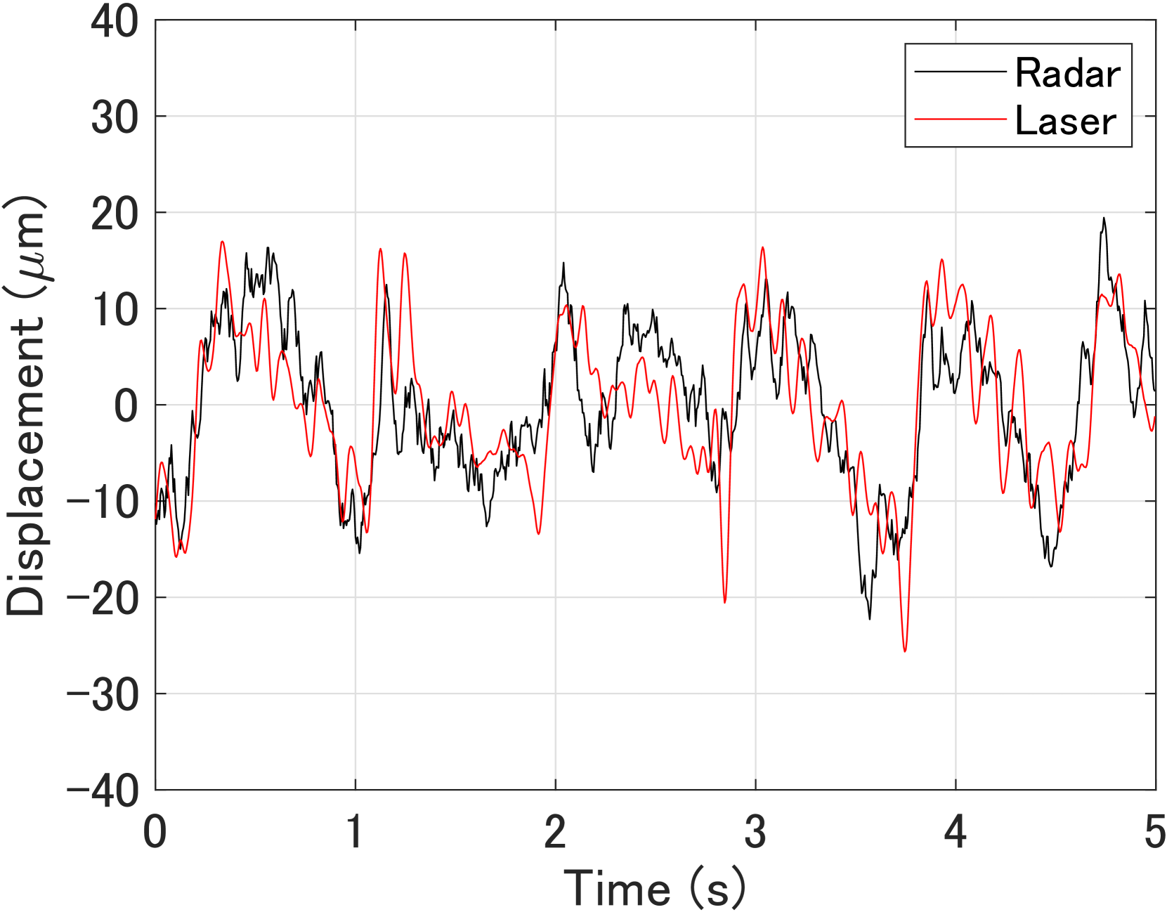
Figs. 5 and 6 show the estimated displacements when the radar position was adjusted using the proposed method for participant A in supine and prone positions, respectively. Here, the black and red lines represent the estimated and reference displacements, respectively. Figs. 7 and 8 show the estimated displacements when the radar position was shifted by m from the case in Figs. 5 and 6.
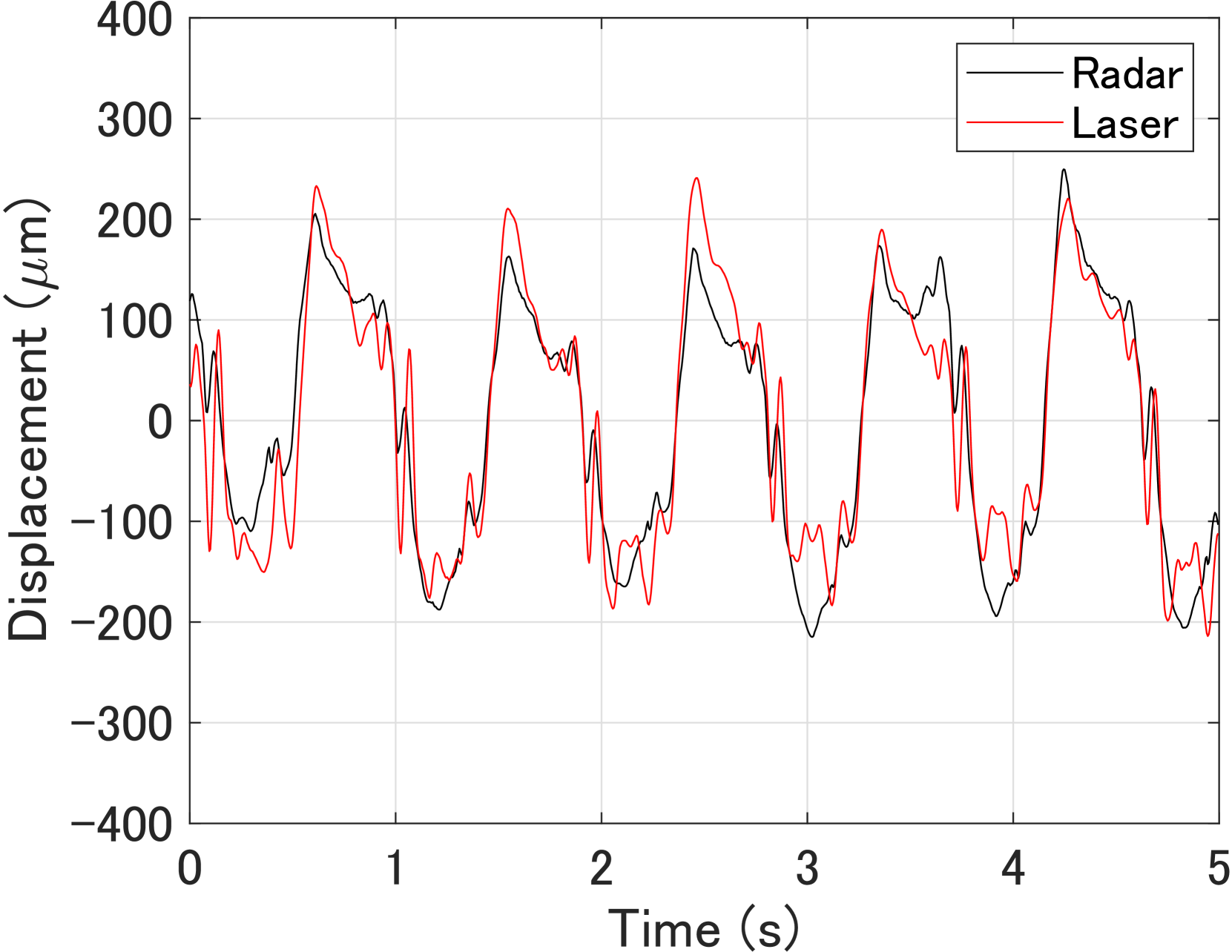
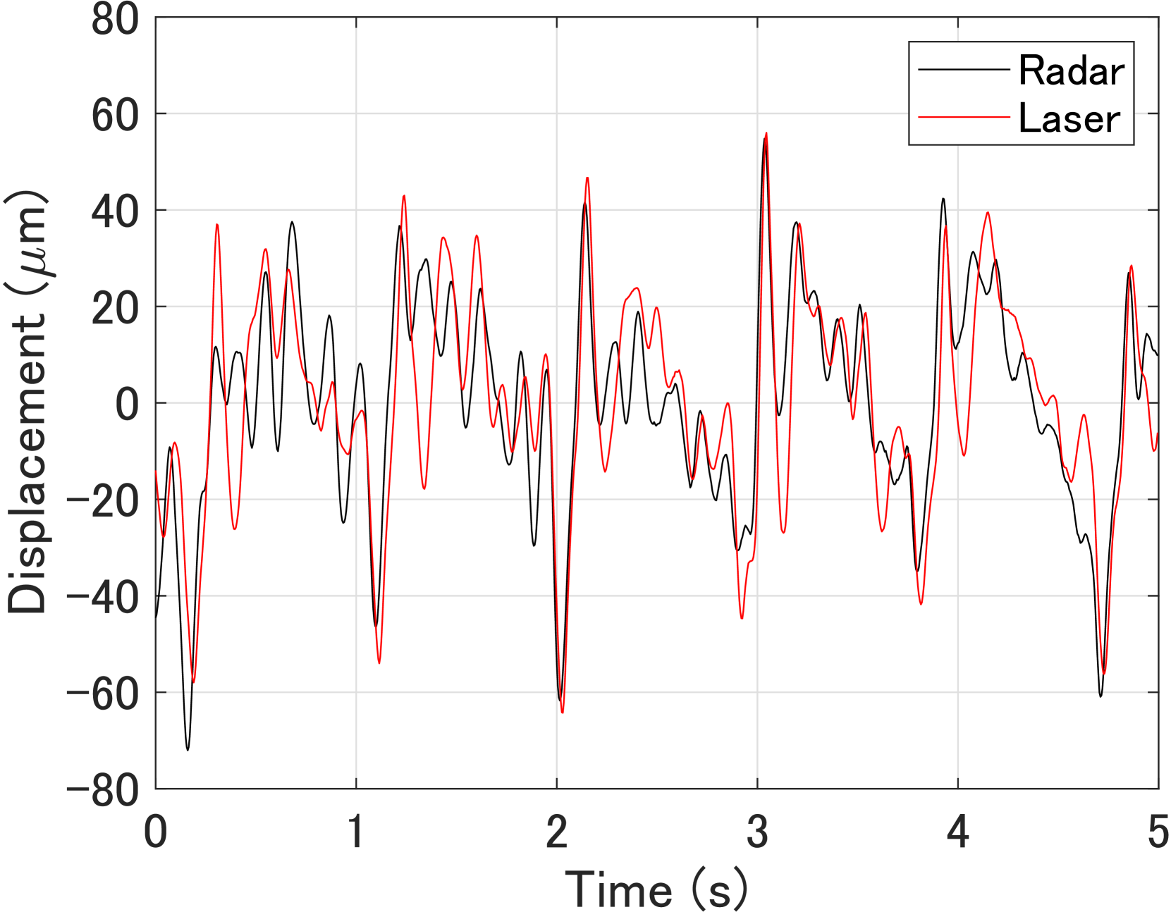
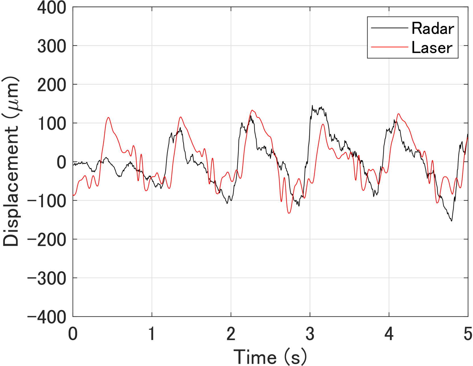
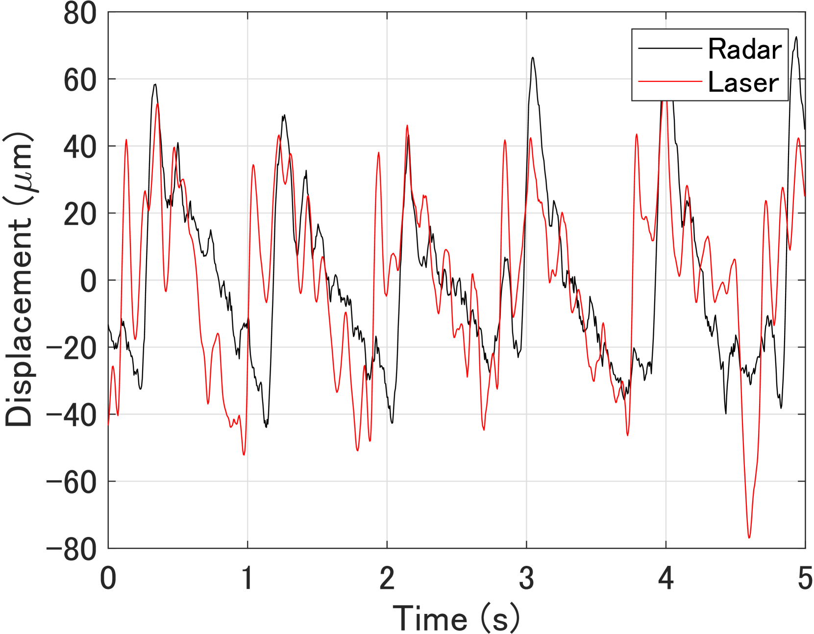
First, Table V summarizes and for six measurements of participant A in a supine position, where and correspond to the chest and front of the thigh, respectively. The average correlation coefficients were and for the conventional and proposed methods, respectively. The average RMS errors were µm and µm for the conventional and proposed methods, respectively. Although the RMS error of the proposed method was 16% larger than that of the conventional method, the correlation coefficient of the proposed method was improved by 19% compared with that of the conventional method.
Next, Table VI summarizes results for participant B in a supine position. The average correlation coefficients were and for the conventional and proposed methods, respectively. The average RMS errors were µm and µm for the conventional and proposed methods, respectively. The proposed method improved the correlation coefficient and RMS error by factors of 1.6 and 2.8, respectively.
Then, Table VII summarizes results for participant A in a prone position. The average correlation coefficients were 0.78 and 0.88 for the conventional and proposed methods, respectively. The average RMS errors were µm and µm for the conventional and proposed methods, respectively. The proposed method improved the correlation coefficient and RMS error by factors of 1.1 and 2.3, respectively.
Finally, Table VIII summarizes results for participant B in a prone position. The average correlation coefficients were and for the conventional and proposed methods, respectively. The average RMS errors were µm and µm for the conventional and proposed methods, respectively. In this case, the RMS error of the proposed method was worse than that of the conventional method by a factor of , whereas the correlation coefficient was improved by a factor of using the proposed method. In this case, the estimation accuracy was degraded with the proposed method, partly owing to the significantly low accuracy in one of the six measurement datasets. If we exclude the last measurement, the average correlation coefficient and RMS error for the proposed method were and µm, respectively.
IV Conclusion
In this study, we proposed a radar sensing system and method for measuring heart pulse waves at multiple sites on the human body using a depth camera and electromagnetic wave scattering analysis. To evaluate the performance of the proposed method, we conducted measurement involving two participants in supine and prone positions using both the proposed and conventional methods. The performances of the methods were evaluated in terms of the correlation coefficient and RMS error in estimating displacement waveforms using reference data taken with laser displacement sensors. Compared with the conventional method, the proposed method improved the estimation accuracy of the body displacement at two positions by 14% and 19% on average with respect to the correlation coefficient and RMS error, respectively. These results indicate that the proposed method can achieve accurate measurement of pulse waves at multiple sites. It will be important to study and develop a method for automatic optimization of the radar position using the proposed approach.
Ethics Declarations
The experimental protocol involving human participants was approved by the Ethics Committee of the Graduate School of Engineering, Kyoto University (permit no. 201916). Informed consent was obtained from all human participants in the study.
References
- [1] R. S. Vasan, M. G. Larson, E. P. Leip, J. C. Evans, C. J. O’Donnell, W. B. Kannel, and D. Levy, “Impact of high-normal blood pressure on the risk of cardiovascular disease,” N. Eng. J. Med., vol. 345, no. 18, pp. 1291–1297, Nov. 2001.
- [2] “World health statistics 2023: monitoring health for the SDGs, sustainable development goals,” World Health Organization, 2023. [Online]. Available: https://www.who.int/data/gho/publications/world-health-statistics. Accessed on: May 8, 2024.
- [3] K. B. Bryant, J. P. Sheppard, N. Ruiz-Negrón, I. M. Kronish, V. Fontil, J. B. King, M. J. Pletcher, K. Bibbins-Domingo, A. E. Moran, R. J. McManus, and B. K. Bellows, “Impact of self-monitoring of blood pressure on processes of hypertension care and long-term blood pressure control,” J. Am. Heart Assoc., vol. 9, no. 15, Jul. 2020.
- [4] R. Mukkamala, J.-O. Hahn, O. T. Inan, L. K. Mestha, C.-S. Kim, H. Töreyin, and S. Kyal, “Toward ubiquitous blood pressure monitoring via pulse transit time: theory and practice,” IEEE Trans. Biomed. Eng., vol. 62, no. 8, pp. 1879–1901, Aug. 2015, DOI: 10.1109/TBME.2015.2441951.
- [5] P. C.-P. Chao, C.-C. Wu, D. H. Nguyen, B.-S. Nguyen, P.-C. Huang, and V.-H. Le, “The machine learnings leading the cuffless PPG blood pressure sensors into the next stage,” IEEE Sens. J., vol. 21, no. 11, pp. 12498–12510, Jun. 2021, DOI: 10.1109/JSEN.2021.3073850.
- [6] X. He, R. A. Goubran, and X. P. Liu, “Secondary peak detection of PPG signal for continuous cuffless arterial blood pressure measurement,” IEEE Trans. Instrum. Meas., vol. 63, no. 6, pp. 1431–1439, Jun. 2014, DOI: 10.1109/TIM.2014.2299524.
- [7] M. S. Roy, R. Gupta, and K. D. Sharma, “BePCon: A photoplethysmography-based quality-aware continuous beat-to-beat blood pressure measurement technique using deep learning,” IEEE Trans. Instrum. Meas., vol. 71, Oct. 2022, DOI: 10.1109/TIM.2022.3212750.
- [8] F. Michler, K. Shi, S. Schellenberger, T. Lenhard, F. Dassel, B. Scheiner, F. Lurz, R. Weigel, and A. Koelpin, “A radar-based vital sign sensing system for in-bed monitoring in clinical applications,” in Proc. 2020 German Microw. Conf. (GeMiC), Cottbus, Germany, 2020, pp. 188–191.
- [9] D. Buxi, J.-M. Redouté, and M. R. Yuce, “Blood pressure estimation using pulse transit time from bioimpedance and continuous wave radar,” IEEE Trans. Biomed. Eng., vol. 64, no. 4, pp. 917–927, Apr. 2017, DOI: 10.1109/TBME.2016.2582472.
- [10] M. P. Ebrahim, F. Heydari, T. Wu, K. Walker, K. Joe, J.-M. Redoute, and M. R. Yuce, “Blood pressure estimation using on-body continuous wave radar and photoplethysmogram in various posture and exercise conditions,” Sci. Rep., vol. 9, Nov. 2019, DOI: 10.1038/s41598-019-52710-8.
- [11] H. Zhao, X. Gu, H. Hong, Y. Li, X. Zhu, and C. Li, “Non-contact beat-to-beat blood pressure measurement using continuous wave Doppler radar,” in 2018 IEEE/MTT-S Int. Microw. Symp. (IMS), Philadelphia, PA, USA, 2018, pp. 1413–1415.
- [12] J. E. Johnson, O. Shay, C. Kim, and C. Liao, “Wearable millimeter-wave device for contactless measurement of arterial pulses,” IEEE Trans. Biomed. Circuits Syst., vol. 13, no. 6, pp. 1525–1534, Dec. 2019, DOI: 10.1109/TBCAS.2019.2948581.
- [13] L. Lu, C. Li, and D. Y. C. Lie, “Experimental demonstration of noncontact pulse wave velocity monitoring using multiple Doppler radar sensors,” in Proc. 2010 Annual Int. Conf. IEEE Eng. Med. and Biol., Buenos Aires, Argentina, 2010, pp. 5010–5013.
- [14] F. Michler, K. Shi, S. Schellenberger, B. Scheiner, F. Lurz, R. Weigel, and A. Koelpin, “Pulse wave velocity detection using a 24 GHz six-port based Doppler radar,” in Proc. 2019 IEEE Radio Wireless Symp., Orlando, FL, USA, 2019.
- [15] Y. Oyamada, T. Koshisaka, and T. Sakamoto, “Experimental demonstration of accurate noncontact measurement of arterial pulse wave displacements using 79-GHz array radar,” IEEE Sens. J., vol. 21, no. 7, pp. 9128–9137, Apr. 2021, DOI: 10.1109/JSEN.2021.3052602.
- [16] Y. Oyamada, T. Koshisaka, G. Stankaitis, S. M. M. Islam, V. M. Lubecke, O. Borić-Lubecke, and T. Sakamoto, “Laser-based noncontact blood pressure estimation using human body displacement waveforms,” in Proc. 2022 IEEE/MTT-S Intl. Microw. Symp. - IMS 2022, Denver, CO, USA, 2022, pp. 1020–1022.
- [17] E. R. Ranjbar and M. Dehmollaian, “Scattering of an object with impedance surfaces using IPO and MLFMM,” in Proc. 2014 22nd Iranian Conf. Electr. Eng. (ICEE), Tehran, Iran, 2014, pp. 1610–1613.
- [18] E. R. Ranjbar and M. Dehmollaian, “Target above random rough surface scattering using a parallelized IPO accelerated by MLFMM,” IEEE Geosci. Remote Sens. Lett., vol. 12, no. 7, pp.1481–1485, Jul. 2015, DOI: 10.1109/LGRS.2015.2409555.
- [19] A. Mazzinghi, L. Facheris, F. Cuccoli, and A. Freni, “2.5D physical optics based algorithm for vehicles classification through a FM-CW radar,” in Proc. 2018 15th European Radar Conf. (EuRAD), Madrid, Spain, 2018, pp. 257–260.
- [20] W. Zhang, H. Gomez-Sousa, J. Heredia-Juesas, and J. A. Martinez-Lorenzo, “Single-frequency imaging and material characterization using reconfigurable reflectarrays,” IEEE Trans. Microwave Theory Tech., vol. 69, no. 7, pp. 3360–3371, July 2021, DOI: 10.1109/TMTT.2021.3061597.
- [21] M. Arias, L. Perez-Eijo, Y. Rodriguez-Vaqueiro, B. Gonzalez-Valdes, J. Vázquez-Cabo, O. Rubiños-Lopez, A. Pino, and Y. Álvarez, “A physical optics simulator for dielectric bodies characterization using a multistatic radar,” in Proc. 2019 IEEE Int. Symp. Antennas Propag. and USNC-URSI Radio Sci. Mtg., Atlanta, GA, USA, 2019, pp. 819–820.
- [22] L. Corucci, E. Giusti, M. Martorella, and F. Berizzi, “Near field physical optics modelling for concealed weapon detection,” IEEE Trans. Antennas Propag., vol. 60, no. 12, pp.6052–6057, Dec. 2012, DOI: 10.1109/TAP.2012.2210017.
- [23] G. Manfredi, J.-P. Ovarlez, and L. Thirion-Lefevre, “Features extraction of the Doppler frequency signature of a human walking at 1 GHz,” in Proc. IGARSS 2019 - 2019 IEEE Intl. Geosci. and Remote Sens. Symp., Yokohama, Japan, 2019, pp. 2260–2263.
- [24] N. Keerativoranan, P. Hanpinitsak, K. Saito, and J.-I. Takada, “Analysis of non-intrusive hand trajectory tracking by utilizing micro-Doppler signature obtained from Wi-Fi channel state information,” IEEE Access, vol. 8, pp. 176430–176444, Sept. 2020, DOI: 10.1109/ACCESS.2020.3026743.
- [25] L. Perez-Eijo, B. Gonzalez-Valdes, M. Arias, D. Tilves, Y. Rodriguez-Vaqueiro, O. Rubiños-López, A. Pino, F. García-Rial, and J. Grajal, “A physical optics simulator for multireflector THz imaging systems,” IEEE Trans. THz Sci. Technol., vol. 9, no. 5, pp. 476–483, Sept. 2019, DOI: 10.1109/TTHZ.2019.2930918.
- [26] F. Mokhtari-Koushyar and A. A. Shishegar, “Scattering analysis of human body modeled by NURBS surfaces in MM-wave band,” in Proc. 2014 Third Conf. Millimeter-Wave and THz Technol. (MMWATT), Tehran, Iran, 2014/2015.
- [27] M. Vahidpour and K. Sarabandi, “Millimeter-wave Doppler spectrum and polarimetric response of walking bodies,” IEEE Geosci. Remote Sens. Lett., vol. 50, no. 7, pp. 2866–2879, Jul. 2012, DOI: 10.1109/TGRS.2011.2176342.
- [28] K. Konishi and T. Sakamoto, “Automatic tracking of human body using millimeter-wave adaptive array radar for noncontact heart rate measurement,” in Proc. 2018 Asia-Pacific Microw. Conf., Kyoto, Japan, 2018, pp. 836–838.
- [29] T. Sakamoto, K. Konishi, K. Yamashita, M. Muragaki, S. Okumura, and T. Sato, “Adaptive array radar imaging of a human body for vital sign measurement,” in Proc. 2018 IEEE Int. Symp. Antennas Propag. & USNC/URSI National Radio Sci. Mtg., Boston, MA, USA, 2018, pp.617–618.
- [30] A. Shokouhmand, S. Eckstrom, B. Gholami, and N. Tavassolian, “Camera-augmented non-contact vital sign monitoring in real time,” IEEE Sens. J., vol. 22, no. 12, pp. 11965–11978, Jun. 2022, DOI: 10.1109/JSEN.2022.3172559.
- [31] I. V. Mikhelson, P. Lee, S. Bakhtiari, T. W. Elmer, A. K. Katsaggelos, and A. V. Sahakian, “Noncontact millimeter-wave real-time detection and tracking of heart rate on an ambulatory subject,” IEEE Trans. Inf. Technol. Biomed., vol. 16, no. 5, pp. 927–934, Sept. 2012, DOI: 10.1109/TITB.2012.2204760.
- [32] T. Shijo, T. Itoh, and M. Ando, “Visualization of high frequency diffraction based on physical optics,” IEICE Trans. Electron., vol. E87-C, no.9, pp.1607–1614, Sept. 2004.
- [33] K. Takao, M. Fujita, and T. Nishi, “An adaptive antenna array under directional constraint,” IEEE Trans. Antennas Propag., vol. 24, no. 5, pp. 662–669, Sept. 1976, DOI: 10.1109/TAP.1976.1141411.
![[Uncaptioned image]](https://arxiv.org/html/2405.10540v1/x13.png) |
Takehito Koshisaka received the B.E. degree in electrical and electronic engineering from Kyoto University, Kyoto, Japan, in 2021 and the M.E. degree in electrical engineering from the Graduate School of Engineering, Kyoto University, in 2023. |
![[Uncaptioned image]](https://arxiv.org/html/2405.10540v1/x14.png) |
Takuya Sakamoto (Senior Member, IEEE) received a B.E. degree in electrical and electronic engineering from Kyoto University, Kyoto, Japan, in 2000 and M.I. and Ph.D. degrees in communications and computer engineering from the Graduate School of Informatics, Kyoto University, in 2002 and 2005, respectively. From 2006 through 2015, he was an Assistant Professor at the Graduate School of Informatics, Kyoto University. From 2011 through 2013, he was also a Visiting Researcher at Delft University of Technology, Delft, the Netherlands. From 2015 until 2019, he was an Associate Professor at the Graduate School of Engineering, University of Hyogo, Himeji, Japan. In 2017, he was also a Visiting Scholar at University of Hawaii at Manoa, Honolulu, HI, USA. From 2019 until 2022, he was an Associate Professor at the Graduate School of Engineering, Kyoto University. From 2018 through 2022, he was also a PRESTO researcher of the Japan Science and Technology Agency, Japan. Since 2022, he has been a Professor at the Graduate School of Engineering, Kyoto University. His current research interests lie in wireless human sensing, radar signal processing, and radar measurement of physiological signals. Prof. Sakamoto was a recipient of the Best Paper Award from the International Symposium on Antennas and Propagation (ISAP) in 2004; the Young Researcher’s Award from the Information and Communication Engineers of Japan (IEICE) in 2007; the Best Presentation Award from the Institute of Electrical Engineers of Japan in 2007; the Best Paper Award from the ISAP in 2012; the Achievement Award from the IEICE Communications Society in 2015, 2018, and 2023; the Achievement Award from the IEICE Electronics Society in 2019; the Masao Horiba Award in 2016; the Best Presentation Award from the IEICE Technical Committee on Electronics Simulation Technology in 2022; the Telecom System Technology Award from the Telecommunications Advancement Foundation in 2022; and the Best Paper Award from the IEICE Communication Society in 2007 and 2023. |


No comments:
Post a Comment