Summary of New Chinese Hypersonic Heat Management Technology

1. Innovative Cooling Device: A Chinese military research team led by Li Shibin from the National University of Defence Technology has developed a new cooling device capable of managing intense heat during hypersonic flight. Key features include:
- Operating duration of up to 2.5 hours
- Suitable for long-duration, high-speed missions
- Uses thermal energy from aerodynamic heating to drive an active cooling cycle
- Ensures proper functioning of critical components under strenuous flight conditions
2. Cylindrical Cooling System: This system was designed for new generation hypersonic aircraft and underwent ground tests in 2022 or earlier. It features:
- A water storage container at the top filled with an aerogel that can absorb water
- Ability to control cabin temperature below 100°C during the first 50 minutes of flight
- After 50 minutes, the coolant boils and vaporizes, transferring heat faster
- High-temperature steam is slowly released from a pressure relief valve
- The aerogel structure ensures stable vaporization and thermal insulation
3. Advanced Hypersonic Glide Vehicle (HGV): Chinese scientists reported developing an HGV capable of:
- Exceeding Mach 15 speeds
- Using a "skipping stone" trajectory for extended range and maneuverability
- Maneuvering in and out of the atmosphere
- Potentially maintaining speeds above Mach 17 for extended periods
4. Thermal Protection Technologies: The new cooling device would be used in conjunction with other thermal protection technologies such as high-temperature-resistant coatings and lightweight insulation structures.
It's important to note that while these advancements are significant, the document does not provide extensive technical details on these systems, likely due to their sensitive nature in military applications. The reports suggest that China is making substantial progress in addressing the thermal management challenges of hypersonic flight.
Hypersonic Heat Load
1. The heat production of a scramjet engine at Mach 6 is mentioned to be around 1350 kW, according to the Lander-Nixon diagram referenced in the document.
2. The document states that for Mach 6 flight, the demand for fuel heat sink capacity for scramjet cooling is about 1.8~2.7 MJ/kg.
3. The total heat sink capacity of various hydrocarbon fuels is reported to be in the range of 2500-3500 kJ/kg at temperatures of 550-750°C and pressures of 25-60 bar.
4. For the X-51A waverider (a hypersonic demonstrator), the fuel mass flow rate is given as 0.5 kg/s at Mach 6.
While these figures provide some context, it's important to note that the actual heat load would vary depending on factors such as:
- The specific design of the missile
- Flight speed and altitude
- Duration of flight
- Size and shape of the vehicle
- Materials used in construction
For a more precise answer, one would need to consider the specific missile design and its intended flight profile. The heat load for hypersonic missiles is generally considered to be extremely high, necessitating advanced thermal management solutions.
New Chinese Thermal Management Techniques
1. Innovative Cooling Device: The South China Morning Post reported that a Chinese military research team, led by Li Shibin from the National University of Defence Technology, has developed a new cooling device capable of managing intense heat during hypersonic flight. Key features include:
- Operating duration of up to 2.5 hours
- Suitable for long-duration, high-speed missions
- Uses thermal energy from aerodynamic heating to drive an active cooling cycle
- Ensures proper functioning of critical components under strenuous flight conditions
2. Cylindrical Cooling System: This system was designed for new generation hypersonic aircraft and underwent ground tests in 2022 or earlier. It features:
- A water storage container at the top filled with an aerogel that can absorb water
- Ability to control cabin temperature below 100°C during the first 50 minutes of flight
- After 50 minutes, the coolant boils and vaporizes, transferring heat faster
- High-temperature steam is slowly released from a pressure relief valve
- The aerogel structure ensures stable vaporization and thermal insulation
3. Advanced Hypersonic Glide Vehicle (HGV): Chinese scientists reported developing an HGV capable of:
- Exceeding Mach 15 speeds
- Using a "skipping stone" trajectory for extended range and maneuverability
- Maneuvering in and out of the atmosphere
- Potentially maintaining speeds above Mach 17 for extended periods
4. Thermal Protection Technologies: The documents mention that the new cooling device would be used in conjunction with other thermal protection technologies such as high-temperature-resistant coatings and lightweight insulation structures.
While these advancements are significant, the documents do not provide extensive technical details on these systems, likely due to their sensitive nature in military applications. The reports suggest that China is making substantial progress in addressing the thermal management challenges of hypersonic flight, potentially giving them an advantage in this field.
Steampunk Airconditioning?
1. The system is described as utilizing "the thermal energy from aerodynamic heating to drive an active cooling cycle." This implies it may be using the heat itself as an energy source for the cooling process, rather than electrical energy as would be the case with Peltier devices.
2. It's mentioned that the device has a cylindrical shape with a water storage container at the top filled with an aerogel. This structure doesn't align with typical thermoelectric cooling designs.
3. The cooling process is described as involving phase changes of the coolant (water), including boiling and vaporization. Thermoelectric cooling typically doesn't involve phase changes of the cooling medium.
4. The system releases high-temperature steam through a pressure relief valve, which is not characteristic of Peltier effect cooling.
The description suggests the system might be closer to a type of heat pipe or two-phase cooling system that utilizes phase changes of the coolant for heat transfer. However, without more detailed information, it's not possible to definitively state the exact nature of the technology.
It's worth noting that the term "active cooling cycle" could encompass a wide range of technologies. While thermoelectric cooling is indeed an active cooling method, the limited information provided seems to point towards a different approach. To determine if Peltier effect cooling is involved, we would need more specific technical details about the system's operation and energy sources.
1. Heat-Driven Cooling Cycle: The document states that the system "utilizes the thermal energy from aerodynamic heating to drive an active cooling cycle." This directly supports a hypothesis of using heat as the primary energy input for cooling.
2. Compressor-Evaporator System: Using heat to drive a compressor connected to an evaporator for cooling is a viable interpretation. This could be similar to a thermally-activated cooling system.
3. Phase Changes: The description mentions coolant boiling, vaporization, and steam release, which are consistent with a system involving compression and expansion cycles.
4. Water as Coolant: The use of water and aerogel suggests a system that might be leveraging phase changes for cooling, which fits with the compressor-evaporator idea.
5. Long Duration: The system's ability to operate for up to 2.5 hours suggests an efficient use of the available thermal energy, which would be necessary for a heat-driven cooling cycle.
Possible Systems This Could Represent:
1. Absorption Cooling System: Uses heat to drive a chemical process that creates a cooling effect, often using a refrigerant-absorbent pair.2. Ejector Cooling System: Uses high-pressure steam to create a low-pressure area, causing evaporation and cooling.
3. Thermally-Driven Heat Pump: Uses heat to power a cycle that moves heat from a cooler area to a warmer area.
4. Vortex Tube Cooling: Though less likely, it uses compressed gas to generate hot and cold air streams.
China's hypersonic cooling innovation puts heat on US - Asia Times
China’s latest hypersonic cooling technology breakthrough marks a significant leap forward in the race to dominate global high-speed flight and missile systems.
This month, the South China Morning Post (SCMP) reported that a Chinese military research team, led by assistant researcher Li Shibin from the National University of Defence Technology, has developed an innovative cooling device capable of managing the intense heat generated during hypersonic flight.
The SCMP report says that the device operates for up to 2.5 hours and is a crucial advancement for long-duration, high-speed missions, allowing for journeys from one side of the Earth to the other. The team’s invention is detailed in the Journal of National University of Defence Technology.
SCMP says that the cylindrical cooling system utilizes the thermal energy from aerodynamic heating to drive an active cooling cycle, ensuring the proper functioning of critical components under strenuous flight conditions.
It mentions that China’s race to develop hypersonic capabilities, alongside the US and Russia, has led to test flights of long-range hypersonic unmanned aircraft, with plans for crewed global flights by 2035.
In addition, the report points out that China unveiled the DF-17, the world’s first hypersonic glide missile, in 2019. Recent US Army tests of a similar weapon highlight the rapid progress in this field.
However, as a US congressional investigation noted last year and the SCMP points out in its report, managing the extreme heat generated in hypersonic flight remains a fundamental challenge.
SCMP reported that Chinese scientists are advancing hypersonic weapon technology with a new HGV capable of exceeding Mach 15 speeds. This vehicle utilizes a “skipping stone” trajectory for extended range and maneuverability.
SCMP notes that the science team, led by Yong Enmi from the China Aerodynamics Research and Development Centre, aims to surpass the foundational work of Qian Xuesen, the “father of Chinese rockets,” who conceptualized hypersonic gliders in the 1940s.
It notes that these gliders, exemplified by China’s DF-17 missile, can penetrate air defenses with unprecedented speed and agility.
The SCMP report says the latest design, outlined in a June article in the Chinese Journal of Astronautics, includes a solid-fuel booster capable of multiple ignitions. It mentions that the design enables the HGV to maneuver in and out of the atmosphere and extend its kill range by more than a third.
SCMP notes that this development could shift the primary use of hypersonic gliders from regional to global operations. However, it points out that while the technology is not yet combat-ready, additional systems for flexible trajectory adjustments are required.
The report also highlights that the new aircraft’s design, which integrates the fuselage with wings and features novel algorithm trajectory optimization, has shown potential in simulations to maintain speeds above Mach 17 for extended periods, suggesting the capability to strike almost any global target.
As China accelerates its hypersonic technology, the US grapples with detecting and defending against these rapidly evolving threats.
In a June 2024 report, the US Congressional Research Service (CRS) noted hypersonic weapons’ agility and low-altitude flight capability could challenge current detection and defense systems.
Terrestrial-based radars often struggle to detect hypersonic weapons until late in flight because of their limited line of sight. This deficiency, the CRS report says, leaves defenders with little time to launch interceptors to stop the incoming weapon.
US defense officials have reported that the current sensor systems on land and space are ineffective in identifying and monitoring hypersonic weapons, according to CRS. Former undersecretary of defense for research and engineering Mike Griffin says hypersonic targets appear 10 to 20 times dimmer than the objects typically tracked by US satellites in geostationary orbit, as quoted in the CRS report.
Although the US is accelerating its hypersonic weapons program, it faces challenges addressing the intense heat generated during hypersonic flight.
This month, the CRS highlighted the significant challenge of heat control and thermal management in hypersonic flight, where vehicles travel at speeds exceeding Mach 5. The CRS report mentions that at such extreme velocities, the friction between the vehicle’s surface and the atmosphere generates intense heat, necessitating advanced thermal protection systems.
The report mentions that the US has built new hypersonic test facilities to find solutions for those thermal challenges, such as the University of Notre Dame’s Mach 6 and Mach 10 quiet wind tunnels and Purdue University’s Mach 8 quiet wind tunnel. It also mentions plans for constructing a kilometer-long Mach 10 wind tunnel at Texas A&M University in partnership with Army Futures Command.
While the US builds cutting-edge test facilities to tackle the intense heat of hypersonic flight, its hypersonic weapons program has been criticized for overlooking critical design and transparency issues in its rush to deploy the advanced weapons.
In a critical evaluation of the US Department of Defense’s (DOD) hypersonic weapons development, the US Government Accountability Office (GAO) released a report in July 2024 highlighting several challenges.
The GAO found that the DOD’s focus on rapid delivery has often overlooked the integration of user feedback and modern digital engineering tools, which could enhance design efficiency and reduce costs.
The GAO report also underscored the difficulty in estimating costs due to limited historical data, with programs like the Navy’s Conventional Prompt Strike (CPS) relying heavily on expert opinions, potentially introducing bias.
Furthermore, the GAO noted a lack of transparency with the US Congress regarding enterprise-level risks and progress in fielding hypersonic systems.
Amidst criticism directed against the US’s rushed and opaque hypersonic development, a new partnership with Australia aims to bolster defenses and counter the growing hypersonic threat from China and Russia.
Reuters reported this month that Australia and the US are advancing toward joint production of hypersonic missiles, as revealed by US Republican lawmaker Michael McCaul during a visit to Sydney.
Reuters mentions that McCaul, who chairs the US House Foreign Affairs Committee, highlighted the strategic partnership’s potential to alleviate pressure on the US defense industrial base and enhance regional security against emerging threats.
The Reuters report says the collaboration, spurred by China’s hypersonic tests in 2021 and Russia’s use in Ukraine, aims to enable Australia to counter rapid strikes. McCaul notes that current defenses cannot intercept a Chinese hypersonic attack.
Reuters points out that the initiative aligns with the AUKUS alliance’s goals, which include transferring nuclear-powered submarines to Australia and jointly developing cutting-edge defense technologies.
Chinese team thinks ‘outside the box’ to find a cool solution to hypersonic heat
A Chinese military research institute says it has developed an efficient way to control one of the biggest challenges to hypersonic flight: searing heat.
The new cooling device can operate for up to 2½ hours – significantly longer than previously reported solutions and enough for a journey from one side of the Earth to the other.
It has a simple structure and the cost is relatively low because it does not have complex components like heat pipes or booster pumps. And it is reusable – it just needs clean water added before each flight.
The team behind it was led by Li Shibin, an assistant researcher with the National University of Defence Technology’s College of Aerospace Science and Engineering in Changsha, Hunan.
They reported on their invention in the Journal of National University of Defence Technology this month.
“The system effectively utilises the thermal energy generated by aerodynamic heating as the driving force for the active cooling cycle, achieving autonomous pressurisation and cooling of the heat control device,” the paper said.
“It ensures the normal operation of critical components in special sections under long-duration flight conditions and meets the design objective of efficient thermal utilisation for hypersonic aircraft.”

China is in a race with the United States and Russia to develop hypersonic capabilities. It has conducted test flights of long-duration, long-range hypersonic unmanned aircraft and aims for crewed global flights by 2035.
There is also a rush to develop hypersonic weapons, which can travel at more than five times the speed of sound within the atmosphere and have unpredictable trajectories – making them difficult to intercept.
China unveiled the world’s first hypersonic glide missile, the DF-17, five years ago. The US Army tested a similar weapon, the C-HGB, this month and hopes to get production approval soon.
But flight duration is limited. Some estimates say the C-HGB can fly for less than half an hour, with a range of about 3,000km (1,860 miles), while China’s new hypersonic weapons can enter and exit the atmosphere multiple times, with a global range, flight time of over an hour and a top speed close to Mach 20.
These weapons pose new challenges for thermal management.
“In high-speed flight environments, the heat flux density on the aircraft’s surface increases rapidly to the power of three of the flight speed,” Li and his team wrote in the paper. “Especially under long-duration conditions, the accumulation of aerodynamic heat makes thermal protection a crucial factor affecting the success or failure of the project.”
Traditional cooling approaches no longer work in these conditions. To find a solution the team said they had to “think outside the box”.
Their cylindrical cooling device was designed for the new generation of hypersonic aircraft and underwent ground tests in 2022 or earlier, according to the paper.
The bottom of the cylinder is in contact with the underside of the aircraft, where it heats up. During flight, that heat moves to the top of the cylinder, while cooling water flows clockwise inside the device, driven by the pressure produced by temperature-sensitive components. A water storage container at the top is filled with an aerogel that can absorb water.
Testing has shown that the device can control the cabin temperature to below 100 degrees Celsius (212 degrees Fahrenheit) during the first 50 minutes of flight, according to the paper. After that, the coolant starts to boil and vaporise, transferring heat at a faster speed until it reaches peak efficiency by the 66th minute.
At this point, high-temperature steam is slowly released from a pressure relief valve and the porous structure of the aerogel ensures a stable and prolonged vaporisation process. The aerogel also provides thermal insulation, keeping the cabin temperature low even after the water evaporates.
Li’s team said their device was simpler than high-temperature heat pipes that use liquid metal as a cooling medium. They also claim it would be easier to put into practice than active cooling systems driven by external forces such as devices that simulate perspiration.
“Without increasing system complexity, it can maximise the use of a cooling medium to absorb and release heat in different phases, achieving optimal temperature control,” the scientists said.

26:05
China is boldly going where no one has gone before
China is boldly going where no one has gone before
Since hypersonic flight requires an extensive and complex thermal management system, the new device would need to be used in conjunction with other thermal protection technologies such as high-temperature-resistant coatings and lightweight insulation structures.
The device would be suitable to cool critical areas including air rudders and important electronic equipment, according to the team.
A US congressional investigation last year found that inadequate cooling systems were the main reason the United States is lagging behind China on hypersonic weapons.
“The fundamental remaining challenge involves managing the extreme heat that hypersonic missiles are exposed to by travelling at high speeds in the atmosphere for most of their flight,” said the congressional report released in January 2023.
“Shielding hypersonic missiles’ sensitive electronics, understanding how various materials perform, and predicting aerodynamics at sustained temperatures as high as 3,000 degrees Fahrenheit require extensive flight testing,” it said. “Tests are ongoing, but failures in recent years have delayed progress.”
Optimization of Power and Thermal Management System of Hypersonic Vehicle with Finite Heat Sink of Fuel
Font Type:
Arial Georgia Verdana
Open AccessArticle
by
Liang Guo1,†, Liping Pang1,*,†, Jingquan Zhao1 and Xiaodong Yang2,1
School of Aviation Science and Engineering, Beijing University of Aeronautics and Astronautics, Beijing 100191, China2
Institute of Artificial Intelligence, Beijing University of Aeronautics and Astronautics, Beijing 100191, China*
Author to whom correspondence should be addressed.†
These authors contributed equally to this work.
Submission received: 21 June 2022 / Revised: 15 July 2022 / Accepted: 18 July 2022 / Published: 22 July 2022
Abstract
The scramjet of hypersonic vehicles faces severe high-temperature challenges, but the heat sink available for scramjet cooling is extremely finite. It is necessary to optimize its power and thermal management system (PTMS) with a finite heat sink of hydrocarbon fuel. This paper proposes a two-level optimization method for the PTMS of hypersonic vehicles at Mach 6. The PTMS is based on a supercritical carbon dioxide (SCO2) closed Brayton cycle, and its heat sink is airborne hydrocarbon fuel. System-level optimization aims to obtain the optimal system parameters for the PTMS. The minimum fuel weight penalty and the minimum heat sink consumption of fuel are the optimization objectives. The segmental (SEG) method is used to analyze the internal temperature distribution of fuel–SCO2 heat exchangers in the system-level optimal solution set. This ensures the selected optimal solutions meet the requirement of a pinch temperature difference greater than or equal to 10 °C. Further, the component-level optimization for the fuel–SCO2 heat exchanger is carried out based on the selected optimal solutions. The lightest weight of the heat exchanger and the minimum entropy production are the optimization objectives in this step. Finally, the optimal system parameters and the optimal key component parameters can be searched using this presented two-level optimization method.
1. Introduction
One of the key technologies of hypersonic flight is the cooling of the scramjet [1,2,3]. The combustion chamber of the scramjet is in a harsh thermal environment, which even the most advanced composite materials cannot withstand [4]. Traditional aircraft can use cooling air as a heat sink [5]. For hypersonic vehicles, airflow cannot be used as a heat sink due to the excessive temperature, so hydrocarbon fuel becomes the main heat sink [6]. Therefore, the hypersonic vehicle faces the tough problem of the finite heat sink. The design of the power and thermal management system (PTMS) should be paid more attention to.
The application of regenerative cooling technology in X-51A flight tests successfully verified the feasibility of scramjet cooling with endothermic hydrocarbon fuel [7]. It made full use of the chemical heat sink of fuel through the thermal cracking reaction in the cooling channels of the scramjet [8]. The PTMS based on fuel vapor turbine was proposed for the first time in the Hy-Tech program of the United States. In this system, the fuel pyrolysis vapor expands to drive the fuel pump [9]. Zhang et al. [10] evaluated the working capacity performance of the fuel vapor turbine and found that the fuel vapor turbine has enough power to drive a generator, in addition to a fuel pump. The closed Brayton cycle based on supercritical carbon dioxide (SCO2) utilizes SCO2 to exchange the high-temperature heat from the scramjet. This cycle avoids the direct heat exchange between the scramjet and fuel, which is easy to coke, and blocks the cooling channels when the incomplete pyrolysis reaction occurs [11,12,13]. Compared with hydrocarbon fuel, SCO2 is more reliable and stable [6]. It converts part of the high-temperature waste heat of the scramjet into electricity, and the fuel only needs to cool the residual heat. It can improve the cooling capacity of the fuel heat sink. Guo et al. [14] summarized the advantages and disadvantages of the above schemes and proposed a new PTMS based on a SCO2 cycle and a fuel vapor turbine. This PTMS met the cooling and high-power electricity demands at the same time for long-endurance hypersonic vehicles.
Many scholars conducted optimization research on the PTMS of hypersonic vehicles. Cheng et al. [6] optimized and compared the electric power performance between the simple recuperated and recompressing SCO2 cycles. They found that the former utilizes more cooling capacity of fuel. Miao et al. [12] compared the performance of three typical closed Brayton cycle layouts, namely simple, recuperated and SCO2 cycles. They proposed an improved scheme of the SCO2 cycle with lower cooling fuel consumption. Marchionni et al. [15] studied eight different SCO2 cycles and revealed that the complex SCO2 cycle configurations led to higher efficiency and costs. The existing studies on the PTMS of hypersonic vehicles mainly focused on system scheme design and thermodynamic characteristics optimization. So far, few studies considered the design of system-level and component-level optimization at the same time.
The total mass of the take-off period method is often used to evaluate the performance of airborne equipment [16,17]. It converts various losses caused by the analyzed system into the mass of fuel consumed to transport these masses and generate the required power [18]. Total fuel weight penalty can evaluate and compare different schemes of PTMSs.
Considering fuel weight penalty and power-to-weight Ratio (PWR), the closed Brayton cycle based on SCO2 for hypersonic vehicles usually adopts a printed circuit heat exchanger (PCHE) [13,19,20,21,22,23]. PCHE is a high-temperature heat exchanger that exchanges the heat from SCO2 to fuel. Because the physical properties of SCO2 and fuel vary greatly with temperature and pressure [12], it is necessary to adopt the segmental (SEG) method. It divides PCHE into several sub-heat exchangers, and then the detailed temperature of each sub-heat exchanger can be calculated [24]. The SEG method can be used to solve the question of the unreasonable pinch temperature difference and analyze the feasibility of heat transfer. Li et al. [24] proved that the maximum deviation between the heat exchange rate predicted by the SEG method and the experimental data was less than 5%. Entropy generation should also be considered while minimizing the weight of the heat exchanger [25]. Bejan stated that entropy generation should play a central role in heat transfer analysis [26]. Guo et al. proved that the heat transfer entropy generation is far larger than the frictional entropy generation by the SEG method [27].
For hypersonic vehicles with finite heat sink, a concerning goal is to optimize a PTMS to absorb as much heat and produce as much power as possible. In this paper, a two-level optimization method for the PTMS based on a SCO2 closed Brayton cycle is established by non-dominated sorting genetic algorithms (NSGA-II) [28,29]. Simulation models are validated using published experimental data. The effects of optimization variables on the PTMS are discussed in detail. Furthermore, the optimal parameters of the system and key components are determined, and further analysis is carried out to compare the optimization results.
2. Method
2.1. System Description
For the traditional regenerative cooling scheme for the scramjet, the hydrocarbon fuel is cracked in the cooling channels of the scramjet wall. This easily leads to coke and blocks cooling channels, which causes the scramjet to be scrapped after a long-endurance hypersonic flight. Therefore, the PTMS based on SCO2 closed Brayton cycle has been studied in recent years [6,12,13,14], as shown in Figure 1. It moves the easily coking process from the cooling channels of the scramjet wall to the fuel–SCO2 heat exchanger. Compared with the high cost of the scramjet, it is economical to replace the blocked heat exchanger. At the same time, the SCO2 scheme can convert part of scramjet waste heat into electric energy to meet the power demand of hypersonic vehicles. In the SCO2 cycle, PCHE is generally adopted for fuel–SCO2 heat exchangers because of its high heat transfer efficiency and because it is lightweight [13]. Considering the space limitations in the vehicle cabin, it is necessary to comprehensively balance between a thermal design and a geometric design of PCHE.
Figure 1. Scheme of PTMS based on SCO2 closed Brayton cycle.
2.2. Two-Level Optimization Method
The two-level optimization method is presented to optimize the PTMS based on the SCO2 closed Brayton cycle with the finite heat sink of hydrocarbon fuel at 6 March. The inputs of the system-level optimization are fuel mass flow, heat production of the scramjet, and PWR of PCHE.
The multi-objective evolutionary algorithm, NSGA-II, is used to complete two-level optimization. It has been widely used in system optimization and heat exchanger design [29,30,31]. According to Ref. [29], the population size is set to 100, the number of generations is set to 100, the cross-over probability is set to 0.9, and the mutation probability is set to 0.1.
In the system-level optimization, the objective functions are to minimize the fuel weight penalty and heat sink consumption of fuel, which can be expressed by a vector:
where fs,1 (XS) and fs,2 (XS) represent min (Mtotal) and min (Qhs), respectively; XS represents the system-level optimization variable vector and can be expressed as:
where xs,1, xs,2 and xs,3 represent the compressor inlet pressure (PS,1, 7.4~11 MPa), heat exchanger efficiency (ηhx, 80~95%), and compressor pressure ratio (πC, 2~5), respectively.
The constraints in the system-level optimization are defined as follows:
where Tmax and Tc,0 represent the maximum temperature of the SCO2 cycle and outlet temperature of the cold side of PCHE, respectively.
After the system-level optimization, the SEG method is used to analyze the solution set of system-level optimization, which ensures the selected optimal solutions meet the pinch temperature difference (ΔTmin) greater than or equal to 10 °C. The component-level optimization for the fuel–SCO2 heat exchanger is carried out based on the above-selected solutions.
In component-level optimization, the objective functions can be expressed by a vector:
where fb,1 (Xb) and fb,2 (Xb) represent the lightest weight and the minimum entropy production (Sg) of PCHE, respectively; Xb represents the component-level optimization variable vector and can be expressed as:
where xb,1, xb,2 and xb,3 represent the channel width (wc, 1~2 mm), core width (W, 0~1 m) and core height (H, 0~1 m), respectively.
The constraints in the component-level optimization are defined as follows:
where Ploss and L represent pressure loss in PCHE and channel length, respectively.
It takes the lightest weight of PCHE and the minimum.
The two-level optimization process is shown in Figure 2.
Figure 2. Two-level optimization process.
The basic parameters of optimization are shown in Table 1.
Table 1. Basic parameters of optimization.
3. Simulation Model and Its Verification
3.1. Simulation Model
(1) Cooling channel model in the scramjet wall
Referring to X-51A, the fuel mass flow rate is 0.5 kg/s at Mach 6 [7]. According to the classic Lander–Nixon diagram, the demand for fuel heat sink capacity for scramjet cooling is about 1.8~2.7 MJ/kg at Mach 6 [32]. For safety reasons, the maximum value of 2.7 MJ/kg is selected in this paper. Thus, the heat production of the scramjet is 1350 kW. All the scramjet heat is assumed to be taken away by SCO2 in the cooling channels.
The relative pressure loss coefficient in cooling channels is defined as follows:
where PS,2 and PS,3 are the inlet and outlet pressures of cooling channels, respectively, MPa; ξcc is the relative pressure loss coefficient in cooling channels and is set to 2% according to Ref. [12].
(2) Turbomachinery model
This type of single-stage radial turbomachinery is adopted in this paper because the power output is less than 300 kW [33,34,35]. For the compressor and turbine, isentropic efficiencies are respectively defined as:
where ηC and ηT are the isentropic efficiencies of compressor and turbine, respectively, %; hS,1, hS,2 and hS,2s are the inlet specific enthalpy, the outlet specific enthalpy, and the ideal outlet specific enthalpy of the compressor, respectively, kJ/kg; hS,3, hS,4 and hS,4s are the inlet specific enthalpy, the outlet specific enthalpy and the ideal outlet specific enthalpy of the turbine, respectively, kJ/kg.
Balje’s chart summarized the dimensionless parameters of the total efficiency for the turbine and compressor. The specific speed and specific diameter are calculated as [36]:
where Ns is the specific speed; Ds is the specific diameter; D is the diameter, m; N is shaft speed, rad/min; V is the volume flow rate, m3/s; Had is the adiabatic enthalpy increase, kJ.
The weight of turbomachinery is calculated as [38]:
where m is the weight of the turbomachinery, kg; k0 is the weight coefficient, and k0 = 180 [38,39].
(3) Heat exchanger model
In the SCO2 cycle, the PCHE is selected because of its high-heat transfer efficiency and low weight and volume [13]. The physical properties of SCO2 dramatically change near its critical point. To obtain higher accuracy, the SEG method is used to complete the design of PCHE. The PCHE adopts a semicircular straight channel because of its low pressure loss coefficient. The basic configuration of PCHE is shown in Figure 3 [24].
Figure 3. PCHE configuration and basic parameters.
In this paper, Incoloy 907 is selected as the material of PCHE, and its maximum allowable temperature is about 1000 °C [40]. The porosity of PCHE is ϕ = 75.8%. The dimensions of the channels are dc/wc = 0.5, tP/wc = 0.51, and tf/wc = 0.015.
The heat transfer of PCHE is assumed to be one-dimensional along its flow direction and ignores its heat transfer to the environment [24]. Then, the PCHE is divided into n sub-heat exchangers with the same heat exchange capability, as shown in Figure 4. So, Qi = Qtotal/n and n = 20 in this paper [27]. Th,i−1 and Tc,i represent hot side and cold side inlet temperatures of the ith sub-heat exchanger, separately. Ph,i−1 and Pc,i represent hot side and cold side inlet pressures of the ith sub-heat exchanger, separately. The size, weight, and other parameters of PCHE can be obtained by the following formulas.
Figure 4. Schematic diagram of SEG method.
For the sub-heat exchanger i, the local energy balance is defined as Equation (15):
where Qi is the heat transfer of each sub-heat exchanger, kW; m is the mass flow rate, kg/s; h is the specific enthalpy, kJ/kg; Subscripts h and c represent the hot side and cold side of the heat exchanger, respectively.
The local heat transfer equation can be given as Equation (16):
where As,h represents the heat exchange area of the hot side, m2; U represents the total convective heat transfer coefficient; and kW/(m2·K), and is calculated with Equation (17):
where tw represents wall thickness, mm; kw represents the thermal conductivity of metal wall, kW/(m·K); As,w represents the heat exchange area of metal wall, m2; α represents the heat transfer coefficient; and kW/(m2·K); ηt represents the overall surface efficiency defined in Equation (18):
where wc represents the channel width, m; ηf represents the fin efficiency of the semicircular channel, and is defined in Equation (19):
where m and t* are dimensionless numbers and normalized fin thickness, separately.
m and t* are calculated with Equations (20) and (21), separately:
where λ represents the thermal conductivity of the fluid, kW/(m·K); Nu is the Nusselt number.
The following formulas are used to calculate laminar and turbulent [24], separately.
where f is fanning friction factor; Re and Pr are the Reynolds number and Prandtl number, separately.
The hydraulic diameter is calculated with Equation (24):
The pressure drop is calculated with Equation (25):
where Li is the length of each sub-heat exchanger; G is the mass flow flux, kg/(m2·s); ρi is the density of the fluid, kg/m3.
The weight, efficiency, PWR, and pressure loss of PCHE are calculated with Equations (26)–(29), separately:
where ρw is the density of metal wall, kg/m3; N is the number of channels; L is channel length, m; ϕ is porosity; ṁ is the mass flow rate of the fluid, kg/s; Ploss is hot side pressure loss of PCHE, %; ΔP is the hot side pressure drop of PCHE, MPa; Ph is hot side inlet pressure of PCHE, MPa.
The initial PWR is estimated to be 10 when the channel width is 1~2 mm. When the fluid inlet parameters on both sides of PCHE are determined, the scheme process of the SEG method is shown in Table 2 [24]:
Table 2. Scheme process of the SEG method.
(4) Fuel vapor turbine model
The specific power generation of the fuel vapor turbine can be calculated with Equation (30) [11]:
where wf,m is the specific power generation of fuel vapor turbine, kJ/kg; p is the average specific heat of fuel, kJ/(kg·K); πfT is pressure drop ratio of fuel vapor turbine; k is the specific heat ratio of fuel.
Then, the total power generation of the fuel vapor turbine, Wf, can be calculated.
(5) Fuel weight penalty calculation
In this paper, the total mass of the take-off period method is employed [16,17,18]. The mass and power consumption of the PTMS can be converted into fuel consumption to evaluate their impact on the performance of the vehicle. Ignoring the weight of the fixed pipeline and power consumption of the fuel pump, the total fuel weight penalty of the PTMS is calculated with Equations (31) and (32) [16]:
where Mtotal is the total fuel weight penalty of the PTMS, kg; Mhx, MC, MT, and MfT are the fuel weight penalty values of PCHE, compressor, turbine in the SCO2 cycle, and fuel vapor turbine, kg; m indicates weight, kg; Ce is the specific fuel consumption, kg/(N·s); τ0 is the endurance time, s; g is gravitational acceleration, m/s2; K is the lift–drag ratio of the aircraft, and is 2.95 at 6 Mach [42]; TSFC is the thrust-specific fuel consumption, s−1, and is 0.001 at 6 Mach [43].
(6) System scheme design
The system scheme design process is shown in Figure 5. Firstly, the initial parameters, Tc,n, ηC, ηS,T, ηP, ηhx, ξhx, ξcc, P1, πC, are given. Based on the criterion of ΔTmin ≥ 10 K, the compressor inlet temperature, TS,1, is assumed. Then, the parameters of the SCO2 cycle and fuel can be obtained under the constraint of Tc,0 < TS,4. Finally, the optimized parameters are obtained.
Figure 5. System scheme design process.
3.2. Model Validation
For the cooling channel model, the heat exchange capacity is assumed to be 1350 kW according to the Lander–Nixon diagram [32]. For the fuel vapor turbine model, its parameters to calculate power generation refer to the experimental results in Ref. [11].
The turbomachinery model is verified using published experimental data. The comparison between simulation and experimental results of impeller diameter is shown in Table 3. The experimental data for compressor and turbine are taken from Refs. [44,45], respectively. The differences are 2.7% and 4.7% respectively, and both are less than 5%.
Table 3. Verification of turbomachinery model.
The heat exchanger model is verified using published experimental data [46]. Experimental parameters of PCHE are shown in Table 4. The comparisons of ηhx at different Th,0 between experiment and simulation results are shown in Table 5. Their differences are less than 3%.
Table 4. Experimental parameters of PCHE.
Table 5. Verification of heat exchanger model.
4. Results and Analysis
4.1. System-Level Optimization
It is assumed that the heat production of the scramjet is 1350 kW at Mach 6. The objective of the system-level optimization is to minimize the consumption of fuel heat sink and the fuel weight penalty. The preliminary optimization solution set is shown in Figure 6, in which the abscissa and the ordinate represent the consumption of the fuel heat sink and the fuel weight penalty, separately. In Figure 6, a point is highlighted with a triangle as an example point. It can be seen that Qhs is less than the heat production of the scramjet (1350 kW). This is because SCO2 converts part of the high-temperature waste heat of the scramjet into electricity, and the fuel only needs to cool the residual heat.
Figure 6. Preliminary optimization solution set and the example point of PTMS.
However, the pinch point may be located inside the fuel–SCO2 heat exchanger, because the physical properties of SCO2 and fuel vary greatly with the change of temperature and pressure [12,24,47]. The internal temperature distribution of PCHEs in the solution set will be further analyzed using the SEG method to ensure the selected solutions meet ΔTmin ≥ 10 °C.
Taking the example point in Figure 6 as an example, the inlet pressure, temperature, and mass flow rate of the PCHE hot side are 7.5 Mpa, 773 °C, and 1.54 kg/s, respectively. The corresponding values on the cold side are 4 MPa, 50 °C, and 0.5 kg/s, respectively. The amount of heat exchange is 1231 kW. Based on these parameters, the variation curve of the water equivalent (cp × ṁ) with temperature is shown in Figure 7a. The square point represents the point with the lowest temperature difference. It can be seen that the temperature difference between SCO2 and fuel is the lowest near 377 °C. Figure 7b shows the temperature change curve in the ith (i = 1~20) sub-heat exchanger with the SEG method. The arrow indicates the solution direction. The fluid temperature difference on both sides gradually becomes smaller, and it is less than 10 K after the 10th sub-heat exchanger. In the 11th sub-heat exchanger, the fluid temperatures on both sides are crossed, but this heat reversal is impossible. This illustrates that the heat exchange process cannot occur under the given conditions. Therefore, these unfeasible solutions should be removed from the preliminary optimization set.
Figure 7. Heat exchange process of example point. (a) Variation curve of water equivalent with the temperature. (b) Temperature variation curve of sub-heat exchanger.
In Figure 8, the selected solutions are marked in black squares to distinguish them from the preliminary solutions in the yellow circle. Circular points represent the infeasible solution, and square points represent the feasible solution.
Figure 8. System-level optimization results after feasible selection with SEG method.
Figure 9 shows the influence of hot side temperature and efficiency on the heat sink consumption of fuel. To ensure the heat exchange process occurring in PCHE, namely ΔTmin ≥ 10 °C, the hot side inlet temperature of the first sub-heat exchanger (Th,0) cannot be too low. The green line in Figure 9a shows the boundary of Th,0, which is 770~800 °C. Similarly, the heat exchanger efficiency cannot be too high. The green line in Figure 9b shows the boundary of ηhx, which is 90~91%. Th,0 and ηhx are consistent with the experimental results [47].
Figure 9. Relationship of Th,0, ηhx and Qhs in feasible solutions. (a) Hot side inlet temperature boundary (b) Efficiency boundary.
Pareto points (A~F) and the Pareto front of the above feasible solutions are shown in Figure 10. The minimum consumption of fuel heat sink corresponds to the abscissa, and the minimum fuel weight penalty corresponds to the ordinate. The square points in black represent the non-dominated solutions, the triangle points in red represent the dominated solutions, and the solid line is the Pareto optimal front. A point is highlighted with a yellow circle as a reference system. The system parameters of Pareto points are shown in Table 6.
Figure 10. System-level optimization results.
Table 6. System parameters of Pareto points.
The following conclusions can be drawn from Figure 10 and Table 6:
- (1)
Fuel weight penalty mainly depends on the weight of PCHE, compressor, and turbines. The weight of PCHE is much greater than that of other components. The initial PWR of PCHE is fixed at 10, so the weight of PCHE depends on the heat exchange capability. Therefore, in the direction shown by Trend 1 in Figure 10, the greater Qhs, the greater Mtotal.
- (2)
For Pareto points of A~F in the direction shown by Trend 2, there is a conclusion opposite to Trend 1. When Qhs is the maximum value of 1251.6 kw, Mtotal is the minimum of 129.6 kg. When Qhs is the minimum value of 1243.6 kw, Mtotal is the maximum of 130.3 kg. This is because the weight of turbomachinery decreases significantly with the increase in Qhs. Qhs and Mtotal become two competitive optimization variables. When Qhs decreases, Mtotal increases accordingly, and vice versa. The Pareto points are located in the regions close to the coordinate axes.
- (3)
The slope of the Pareto front changes significantly near point C (1244.6 kW, 130.0 kg). When Qhs is less than 1244.6 kW, Mtotal increases significantly with the decrease in Qhs. When Qhs is greater than 1244.6 kW, the change rate of Mtotal decreases with the increase in Qhs. Thus, point C can be considered as a compromise between Mtotal and Qhs.
The relationships between optimization variables and objectives are shown in Figure 11.
Figure 11. Relationships between optimization variables and optimization objectives. (a) πC and Qhs (b) πC and Mtotal. (c) P1 and Qhs (d) P1 and Mtotal. (e) ηhx and Qhs (f) ηhx and Mtotal.
The following conclusions can be drawn from Figure 11 and Table 6:
- (1)
On the whole, increasing πC or reducing P1 not only reduces Qhs, but also increases Mtotal. When ηhx is less than 91%, increasing ηhx can reduce Qhs and Mtotal at the same time. Pareto points of A~F have approximately the same ηhx.
- (2)
Tc,n and ṁc are constants, so Qhs depends on Ph, Th,0, ṁh, and ηhx from Section 3. Among the above factors, only Ph and Th,0 change significantly, as shown in Table 6. However, Qhs decreases with the increase in Th and the decrease in Ph, which indicates that Ph is the main influencing factor of Qhs.
- (3)
For Pareto points, Mtotal mainly depends on the weight of turbomachinery. Increasing πC or decreasing P1 leads to a decrease in Had, which in turn leads to an increase in the weight of the turbomachinery from Equations (10)–(14).
4.2. Component-Level Optimization
The component-level optimization is carried out based on the optimal parameters of point C. The lightest weight of PCHE and the minimum entropy production are the optimization objectives. The optimization results are shown in Figure 12. C1~C8 are Pareto points, and the curve is the Pareto front. Entropy production includes heat transfer entropy production (SgT) and pressure entropy production (SgP), which affect the efficiency and pressure loss of PCHE, separately. The relationship curve between SgT and SgP is shown in Figure 13. The detailed parameters of C1~C8 are shown in Table 7.
Figure 12. Component-level optimization results.
Figure 13. The relationship between SgP and SgT.
Table 7. Parameters of C1~C8.
As can be seen from Figure 12, the weight of PCHE decreases from 57.2 kg to 22.2 kg, and Sg increases from 46.3 J/kg·K to 50.4 J/kg·K. Pareto optimal solutions compete with each other, which proves that the weight is reduced at the cost of increasing irreversibility in PCHE. C1~C3 are almost perpendicular to the ordinate, reflecting significant weight reduction. C5~C8 are almost perpendicular to the abscissa, reflecting that the significant increase in Sg. L of C5 is more than 1m, so C3 and C4 can be considered as better choices.
As can be seen from Figure 13, SgT decreases only slightly, so the efficiency of PCHE is almost constant and stable at 90%. With the increase in SgP, Ploss increases from 0.14% to 0.49%. The pressure losses of C3 andC4 are less than 1% and meet the design requirements [20].
C4 is selected, considering its lighter weight and smaller volume. Thus, the optimal efficiency (89.84%) and PWR (38.0) of PCHE are obtained, and the optimal total fuel weight penalty can be calculated as 48.6 kg. According to Equations (2)–(14), the weight and dimensional design of the compressor, turbine in the SCO2 cycle and fuel vapor turbine are calculated as shown in Table 8.
Table 8. Weight and dimensional design of turbomachinery.
The fuel weight penalty of each component is shown in Figure 14. The compressor and turbine are compact components, and the maximum weight is no more than 10 kg, which is consistent with Ref. [34]. The total fuel weight penalty mainly depends on the weight of PCHE, which is greater than the sum of other components.
Figure 14. The fuel weight penalty of each component.
To compare the optimization effect, the reference system and optimization system of C and C4 are used to compare the parameters before and after the two-level optimization. The comparison of optimization results is shown in Figure 15.
Figure 15. Comparison of optimization results.
It can be seen from Figure 15 that the system-level optimization mainly reduces the heat sink consumption of fuel, and the component-level optimization mainly reduces the fuel weight penalty. The system-level optimization can reduce the heat sink consumption of fuel by 20.2 kW and the fuel weight penalty by 1.9 kg. Based on the optimal solution in the system-level optimization, the weight of PCHE can be reduced from 124.5 kg to 30.9 kg in the component-level optimization. Accordingly, the total fuel weight penalty can be further reduced by 83.3 kg.
5. Conclusions
In this study, a two-level optimization method for the PTMS is proposed by NSGA-Ⅱ for hypersonic vehicles at Mach 6. The PTMS is based on a SCO2 closed Brayton cycle with finite chemical heat sink of hydrocarbon fuel. The following conclusions can be obtained:
- (1)
The system-level optimization can obtain the preliminary solution set. To ensure the feasibility of heat exchanger design, the SEG method is employed to analyze the detailed heat transfer process in PCHE. The minimum temperature difference of PCHE is limited to 10 °C, and the unfeasible solutions are removed. The minimum Th,0 is 770~800 °C, and the maximum ηhx is 90% in feasible solutions.
- (2)
The turbomachinery adopts compact components, and their optimal design parameters are given. The results of the component-level optimization show that the weight of PCHE is greater than the sum of other components, and the total fuel weight penalty mainly depends on the weight of PCHE.
- (3)
The proposed two-level optimization method gives the optimal system parameters and the optimal size of key components. It can reduce the heat sink consumption of fuel by 20.2 kW and the fuel weight penalty by 85.2 kg compared to the reference system.
Author Contributions
Conceptualization, X.Y.; Data curation, L.P. and X.Y.; Formal analysis, L.G. and J.Z.; Methodology, L.P., J.Z. and X.Y.; Resources, L.P.; Supervision, L.P.; Validation, J.Z.; Visualization, L.G.; Writing—original draft, L.G.; Writing—review & editing, L.G., L.P., J.Z. and X.Y. All authors have read and agreed to the published version of the manuscript.
Funding
This research received no external funding.
Institutional Review Board Statement
Not applicable.
Informed Consent Statement
Not applicable.
Data Availability Statement
All data is available in this paper.
Conflicts of Interest
No potential conflict of interest was reported by the authors.
Abbreviations
| Symbol | Denotation |
| πC | Compressor pressure ratio |
| πfT | Pressure drop ratio of fuel vapor turbine |
| πT | Pressure drop ratio of turbine in SCO2 cycle |
| C | The efficiency of compressor, % |
| G | The efficiency of the generator, % |
| P | The efficiency of the fuel pump, % |
| S,T | The efficiency of turbine in SCO2 cycle, % |
| ηhx | Heat exchanger efficiency, % |
| ηfT | The efficiency of fuel vapor turbine, % |
| cc | Relative pressure loss coefficient in cooling channels, % |
| hx | Relative pressure loss coefficient of PCHE, % |
| hx,s | Relative pressure loss coefficient of PCHE in system-level optimization, % |
| ṁc | Fuel mass flow rate, kg/s |
| ṁh | SCO2 mass flow rate, kg/s |
| As | Cross area, m2 |
| Ce | The specific fuel consumption, kg/(N·s) |
| core | Heat exchanger core |
| dc | Channel depth, mm |
| dh | Hydraulic diameter, mm |
| G | Mass flow flux, kg/(m2·s) |
| hS,2 | Compressor outlet-specific enthalpy, kJ/kg |
| hS,3 | Turbine inlet-specific enthalpy, kJ/kg |
| hS,2s | Ideal outlet-specific enthalpy of the compressor, kJ/kg |
| hS,24 | Ideal outlet-specific enthalpy of the turbine, kJ/kg |
| H | Core height of PCHE, m |
| K | Lift–drag ratio |
| L | The channel length of PCHE, m |
| Li | The channel length of each subheat exchanger, m |
| M | Weight of PCHE, kg |
| Mtotal | Total fuel weight penalty, kg |
| Ns | Specific speed |
| P1 | Compressor inlet pressure |
| POF | Pareto front |
| Ph | Hot side inlet pressure of PCHE, MPa |
| Ploss | Pressure loss of PCHE, % |
| Pp,in | Inlet pressure of the fuel pump, MPa |
| Pp,out | Outlet pressure of the fuel pump, MPa |
| PS,1 | Compressor inlet pressure, MPa |
| PS,2 | Compressor outlet pressure, MPa |
| PS,3 | Cooling channel outlet pressure, MPa |
| PS,4 | Turbine outlet pressure, MPa |
| PWR | Power-to-Weight Ratio of PCHE |
| Qhs | Heat sink consumption of fuel, kW |
| Qtotal | Engine heat production, kW |
| Sg | Total entropy production, J/kg·K |
| SgP | Pressure entropy production, J/kg·K |
| SgT | Heat transfer entropy production, J/kg·K |
| tf | Fin thickness, mm |
| tp | Plate width, mm |
| tw | Wall thickness, mm; |
| Tc,0 | The outlet temperature of the cold side of PCHE, °C |
| Tc,n | The inlet temperature of the cold side of PCHE, °C |
| Th,0 | The hot side inlet temperature of the first sub-heat exchanger, °C |
| Tmax | The maximum temperature of the SCO2 cycle, °C |
| TS,1 | Compressor inlet temperature |
| TS,4 | Turbine outlet temperature |
| TSFC | Thrust-specific fuel consumption, s-1 |
| wc | Channel width, mm |
| W | Core width of PCHE, m |
| ΔTmin | Pinch temperature difference |
References
- Office of Space Systems Development. NASA Headquarters, Access to Space Study: Summary Report; NASA-TM-109693, 1994-01.1994; NASA: Washington, DC, USA, 1994. [Google Scholar]
- Wu, X.; Yang, J.; Zhang, H.; Shen, C. System design and analysis of hydrocarbon scramjet with regeneration cooling and expansion cycle. J. Therm. Sci. 2015, 24, 350–355. [Google Scholar] [CrossRef]
- Dong, Y.; Wang, E.; You, Y.; Yin, C.; Wu, Z. Thermal protection system and thermal management for combined-cycle engine: Review and prospects. Energies 2019, 12, 240. [Google Scholar] [CrossRef] [Green Version]
- Helenbrook, R.G.; Anthony, F.M. Design of a Convective Cooling System for a Mach 6 Hypersonic Transport Airframe; NASA: Washington, DC, USA, 1971. [Google Scholar]
- Qin, J.; Zhou, W.; Bao, W.; Yu, D. Thermodynamic analysis and parametric study of a closed Brayton cycle thermal management system for scramjet. Int. J. Hydrogen Energy 2010, 35, 356–364. [Google Scholar] [CrossRef]
- Cheng, K.; Qin, J.; Sun, H.; Li, H.; He, S.; Zhang, S.; Bao, W. Power optimization and comparison between simple recuperated and recompressing supercritical carbon dioxide Closed-Brayton-Cycle with finite cold source on hypersonic vehicles. Energy 2019, 181, 1189–1201. [Google Scholar] [CrossRef]
- Hank, J.; Murphy, J.; Mutzman, R. The X-51A scramjet engine flight demonstration program. In Proceedings of the 15th AIAA International Space Planes and Hypersonic Systems and Technologies Conference, Dayton, OH, USA, 28 April–1 May 2008; p. 2540. [Google Scholar]
- Qin, J.; Zhang, S.; Bao, W.; Jia, Z.; Yu, B.; Zhou, W. Experimental study on the performance of recooling cycle of hydrocarbon fueled scramjet engine. Fuel 2013, 108, 334–340. [Google Scholar] [CrossRef]
- Powell, O.A.; Edwards, J.T.; Norris, R.B.; Numbers, K.E.; Pearce, J.A. Development of hydrocarbon-fueled scramjet engines: The hypersonic technology (HyTech) program. J. Propuls. Power 2001, 17, 1170–1176. [Google Scholar] [CrossRef]
- Zhang, D.; Qin, J.; Feng, Y.; Ren, F.; Bao, W. Performance evaluation of power generation system with fuel vapor turbine onboard hydrocarbon fueled scramjets. Energy 2014, 77, 732–741. [Google Scholar] [CrossRef]
- Bao, W.; Qin, J.; Zhou, W.; Zhang, D.; Yu, D. Power generation and heat sink improvement characteristics of recooling cycle for thermal cracked hydrocarbon fueled scramjet. Sci. China Technol. Sci. 2011, 54, 955–963. [Google Scholar] [CrossRef]
- Miao, H.; Wang, Z.; Niu, Y. Key issues and cooling performance comparison of different closed Brayton cycle based cooling systems for scramjet. Appl. Therm. Eng. 2020, 179, 115751. [Google Scholar] [CrossRef]
- Miao, H.; Wang, Z.; Niu, Y. Performance analysis of cooling system based on improved supercritical CO2 Brayton cycle for scramjet. Appl. Therm. Eng. 2020, 167, 114774. [Google Scholar] [CrossRef]
- Guo, L.; Pang, L.P.; Yang, X.D.; Jiao, C.; Cui, S.; Kong, Y.; Jiao, J.; Shen, X. Study on a Power and Thermal Management System for Long Endurance Hypersonic Vehicle. Chin. J. Aeronaut. 2017, 126, 78–93. [Google Scholar]
- Marchionni, M.; Bianchi, G.; Tassou, S.A. Techno-economic assessment of JouleBrayton cycle architectures for heat to power conversion from high-grade heat sources using CO2 in the supercritical state. Energy 2018, 148, 1140–1152. [Google Scholar] [CrossRef]
- Rong, A.; Pang, L.; Jiang, X.; Qi, B.; Shi, Y. Analysis and comparison of potential power and thermal management systems for high-speed aircraft with an optimization method. Energy Built Environ. 2021, 2, 13–20. [Google Scholar]
- Long, C.; Xingjuan, Z.; Chunxin, Y. A new concept environmental control system with energy recovery considerations for commercial aircraft. In Proceedings of the 44th International Conference on Environmental Systems, Tuscon, AZ, USA, 13–17 July 2014. [Google Scholar]
- SAE Aerospace Applied Thermodynamics ManualAircraft Fuel Weight Penalty Due to Air Conditioning; SAE International: Warrendale, PA, USA, 2004.
- Nikitin, K.; Kato, Y.; Ngo, L. Printed circuit heat exchanger thermal–hydraulic performance in supercritical CO2 experimental loop. Int. J. Refrig. 2006, 29, 807–814. [Google Scholar] [CrossRef]
- Marchionni, M.; Chai, L.; Bianchi, G.; Tassou, S.A. Numerical modelling and transient analysis of a printed circuit heat exchanger used as recuperator for supercritical CO2 heat to power conversion systems. Appl. Therm. Eng. 2019, 161, 114190. [Google Scholar] [CrossRef]
- Tsuzuki, N.; Kato, Y.; Ishiduka, T. High performance printed circuit heat exchanger. Appl. Therm. Eng. 2007, 27, 1702–1707. [Google Scholar] [CrossRef]
- Dostal, V. A Supercritical Carbon Dioxide Cycle for Next Generation Nuclear Reactors; MIT-ANP-TR-100; Massachusetts Institute of Technology: Cambridge, MA, USA, 2004. [Google Scholar]
- Tu, Y.; Zeng, Y. Numerical Study on Flow and Heat Transfer Characteristics of Supercritical CO2 in Zigzag Microchannels. Energies 2022, 15, 2099. [Google Scholar] [CrossRef]
- Li, H.; Liu, H.; Zou, Z. Experimental study and performance analysis of high-performance micro-channel heat exchanger for hypersonic precooled aero-engine. Appl. Therm. Eng. 2021, 182, 116108. [Google Scholar] [CrossRef]
- Cavalcanti Alvarez, R.; Sarmiento, A.; Victor Colin Batista, J.; Mantelli, M.H. Entropy generation analysis applied to diffusion-bonded compact heat exchangers. In Proceedings of the AIAA Aviation 2019 Forum, Dallas, TX, USA, 17–21 June 2019; p. 3467. [Google Scholar]
- Bejan, A. Entropy Generation through Heat and Fluid Flow; Wiley: New York, NY, USA, 1982. [Google Scholar]
- Guo, J.; Huai, X. Performance analysis of printed circuit heat exchanger for supercritical carbon dioxide. J. Heat Transf. 2017, 139, 061801. [Google Scholar] [CrossRef]
- Deb, K.; Pratap, A.; Agarwal, S.; Meyarivan, T. A fast and elitist multiobjective genetic algorithm: NSGA-II. IEEE Trans. Evol. Comput. 2002, 6, 182–197. [Google Scholar] [CrossRef] [Green Version]
- Liping, P.; Guoxiang, L.; Hongquan, Q.; Yufeng, F. Flexible operation strategy for environment control system in abnormal supply power condition. Acta Astronaut. 2017, 133, 334–345. [Google Scholar] [CrossRef]
- Foli, K.; Okabe, T.; Olhofer, M.; Jin, Y.; Sendhoff, B. Optimization of micro heat exchanger: CFD, analytical approach and multi-objective evolutionary algorithms. Int. J. Heat Mass Transf. 2006, 49, 1090–1099. [Google Scholar] [CrossRef]
- Wang, S.; Xiao, J.; Wang, J.; Jian, G.; Wen, J.; Zhang, Z. Application of response surface method and multi-objective genetic algorithm to configuration optimization of Shell-and-tube heat exchanger with fold helical baffles. Appl. Therm. Eng. 2018, 129, 512–520. [Google Scholar] [CrossRef]
- Lander, H.; Nixon, A.C. Endothermic fuels for hypersonic vehicles. J. Aircr. 1971, 8, 200–207. [Google Scholar] [CrossRef]
- Fuller, R.L.; Batton, W. Practical considerations in scaling supercritical carbon dioxide closed Brayton cycle power systems. In Proceedings of the Supercritical CO2 Power Cycle Symposium, Troy, NY, USA, 29 April 2009; pp. 29–30. [Google Scholar]
- Fuller, R.; Preuss, J.; Noall, J. Turbomachinery for supercritical CO2 power cycles. Turbo Expo: Power for Land, Sea, and Air. Am. Soc. Mech. Eng. 2012, 44717, 961–966. [Google Scholar]
- Logan, E., Jr. Handbook of Turbomachinery; CRC Press: Boca Raton, FL, USA, 2003. [Google Scholar]
- Balje, O.E. Turbomachines: A Guide to Design, Selection, and Theory; Wiley-Interscience: New York, NY, USA, 1981; 521p. [Google Scholar]
- Holaind, N.; Bianchi, G.; De Miol, M.; Saravi, S.S.; Tassou, S.A.; Leroux, A.; Jouhara, H. Design of radial turbomachinery for supercritical CO2 systems using theoretical and numerical CFD methodologies. Energy Procedia 2017, 123, 313–320. [Google Scholar] [CrossRef]
- Balje, O.E. A study on design criteria and matching of turbomachines: Part a—similarity relations and design criteria of turbines. J. Eng. Power 1962, 84, 83–102. [Google Scholar] [CrossRef]
- Xu, C. Design experience and considerations for centrifugal compressor development. Proc. Inst. Mech. Eng. Part G J. Aerosp. Eng. 2007, 221, 273–287. [Google Scholar] [CrossRef]
- Liang, Z.; Yu, M.; Gui, Y.; Zhao, Q. Corrosion behavior of heat-resistant materials in high-temperature carbon dioxide environment. JOM 2018, 70, 1464–1470. [Google Scholar] [CrossRef]
- NIST Standard Reference Data. The U.S. Secretary of Commerce on behalf of the United States of America. 2011. Available online: http://www.nist.gov/srd/ (accessed on 1 March 2022).
- Zhang, D.; Wang, Y.; Deng, X. Design and computational study of waverider configuration with high performance. J. Beijing Univ. Aeronaut. Astronaut. 2004, 30, 429–433. [Google Scholar]
- El-Sayed, A.F. Pulsejet, ramjet, and scramjet engines. In Fundamentals of Aircraft and Rocket Propulsion; Springer: London, UK, 2016; pp. 315–401. [Google Scholar]
- Zhang, Y.; Peng, M.; Xia, G.; Wang, G.; Zhou, C. Performance analysis of S-CO2 recompression Brayton cycle based on turbomachinery detailed design. Nucl. Eng. Technol. 2020, 52, 2107–2118. [Google Scholar] [CrossRef]
- Cho, J.; Shin, H.; Cho, J.; Baik, Y.-J.; Choi, B.; Roh, C.; Ra, H.-S.; Kang, Y.; Huh, J. Design, flow simulation, and performance test for a partial-admission axial turbine under supercritical CO2 condition. In Proceedings of the ASME Turbo Expo 2018: Turbomachinery Technical Conference and Exposition, Oslo, Norway, 11–15 June 2018. [Google Scholar]
- Kim, S.; Cho, Y.; Kim, M.S.; Kim, M. Characteristics and optimization of supercritical CO2 recompression power cycle and the influence of pinch point temperature difference of recuperators. Energy 2018, 147, 1216–1226. [Google Scholar] [CrossRef]
- Marchionni, M.; Chai, L.; Bianchi, G.; Tassou, S.A. Numerical modelling and performance maps of a printed circuit heat exchanger for use as recuperator in supercritical CO2 power cycles. Energy Procedia 2019, 161, 472–479. [Google Scholar] [CrossRef]
Figure 1. Scheme of PTMS based on SCO2 closed Brayton cycle.
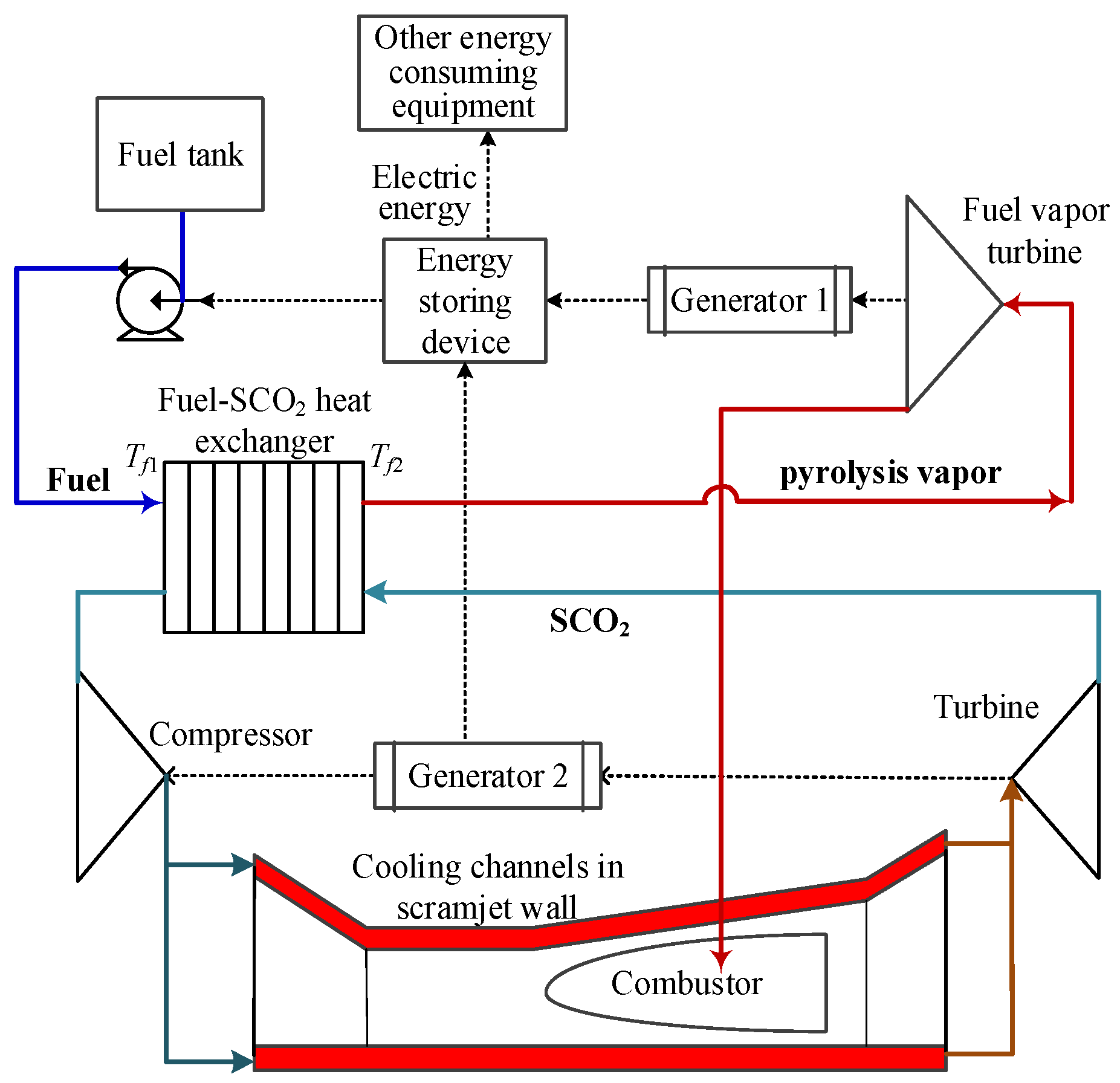
Figure 2. Two-level optimization process.
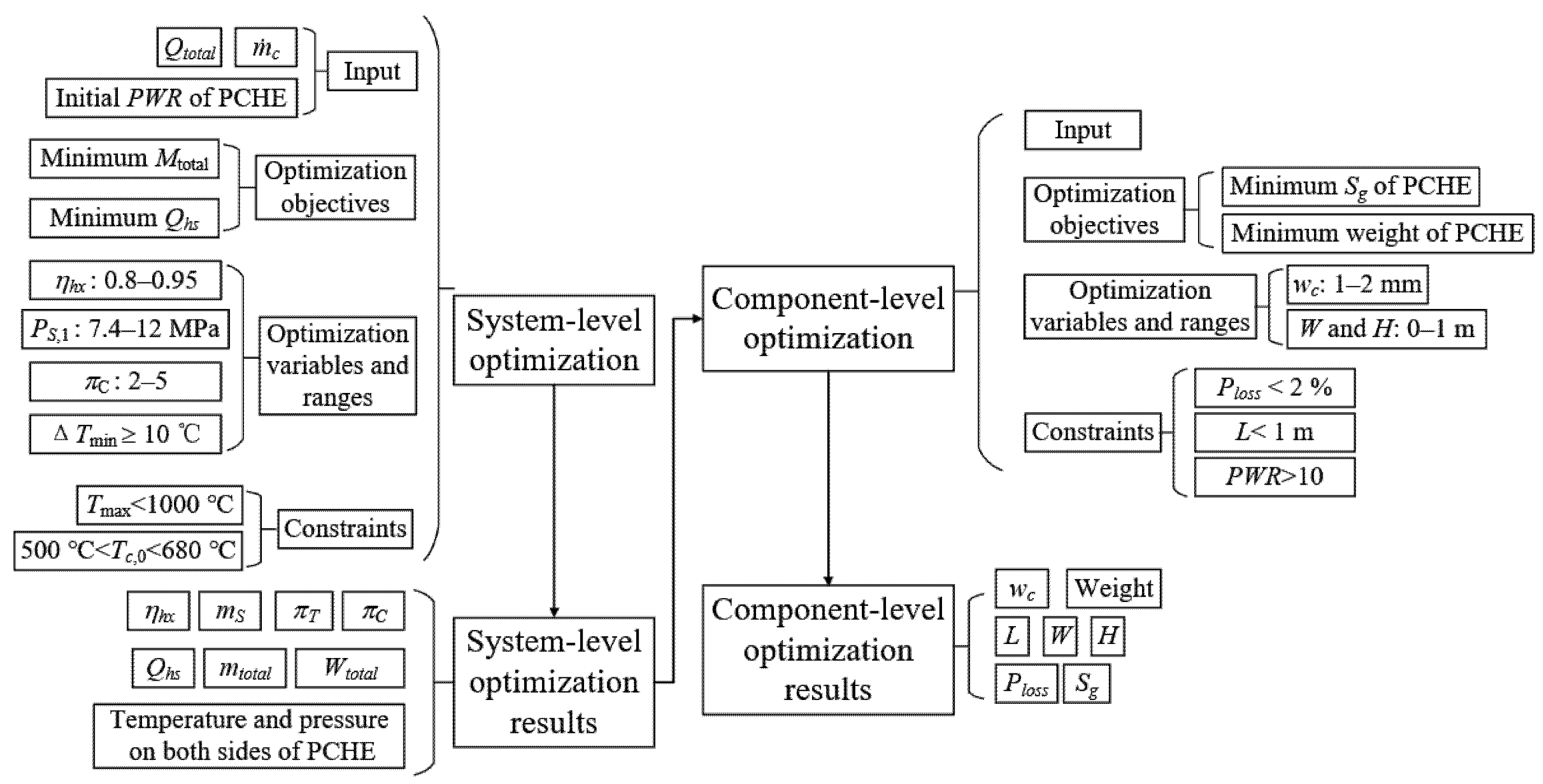
Figure 3. PCHE configuration and basic parameters.
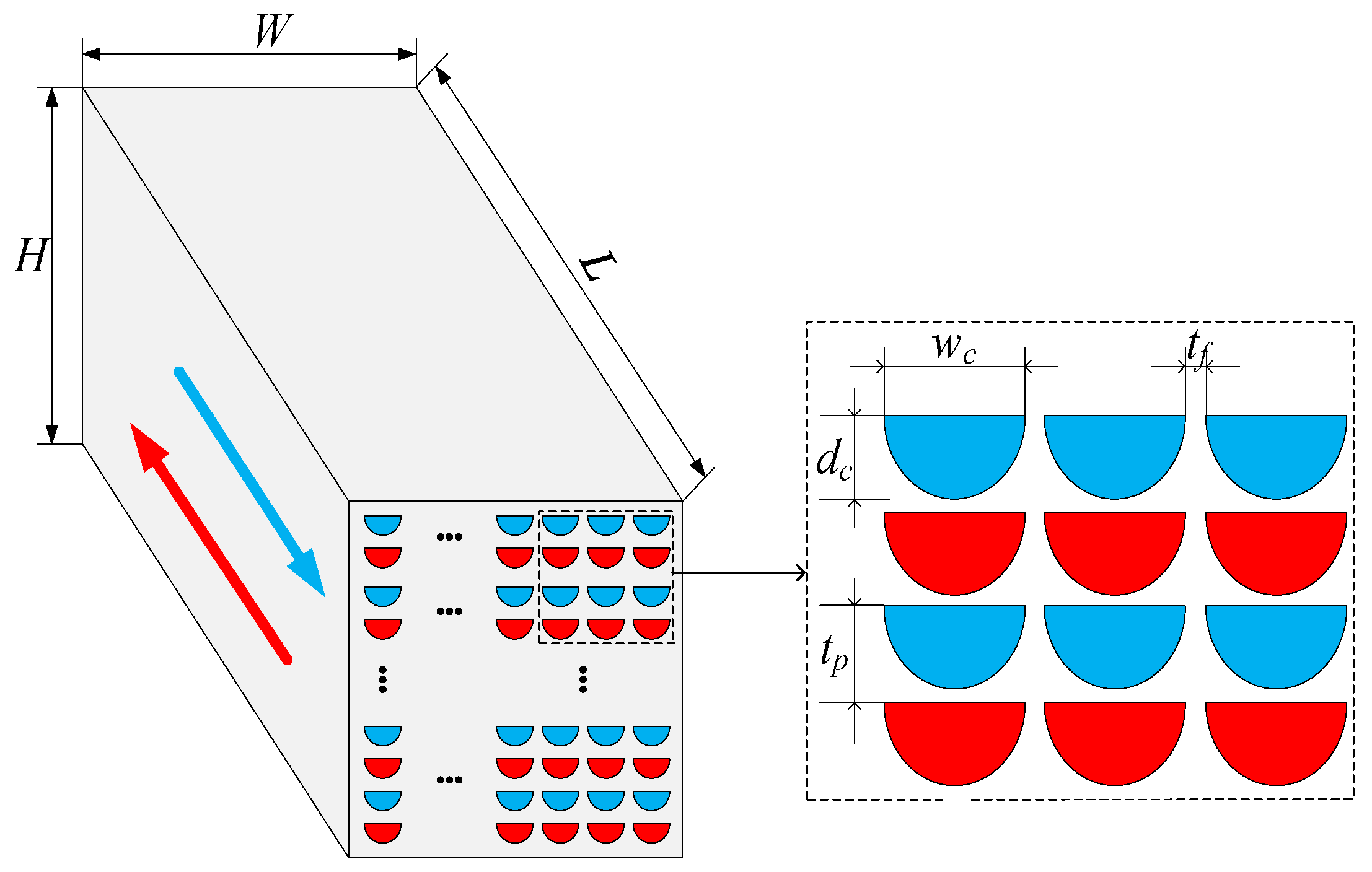
Figure 4. Schematic diagram of SEG method.
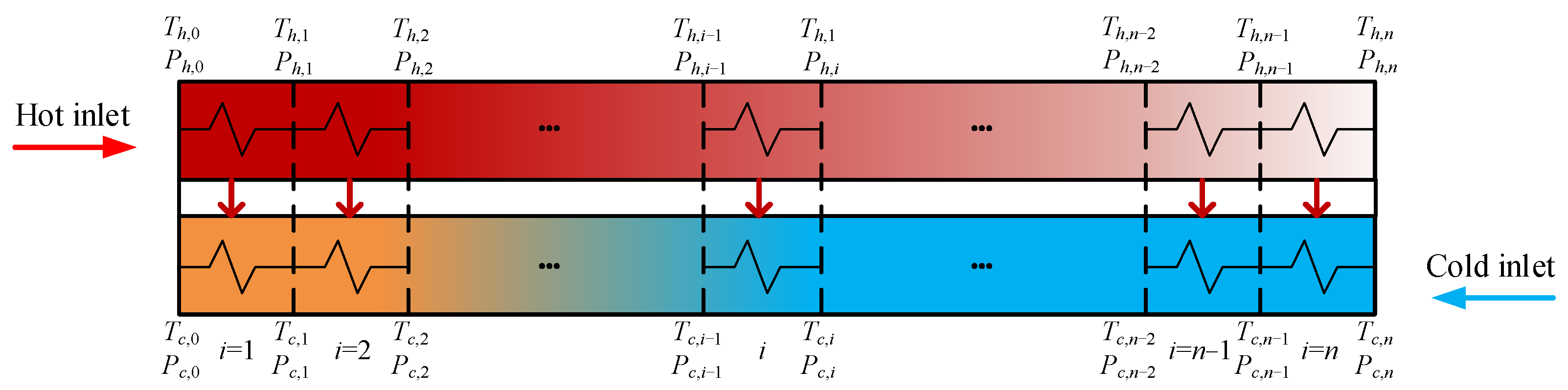
Figure 5. System scheme design process.
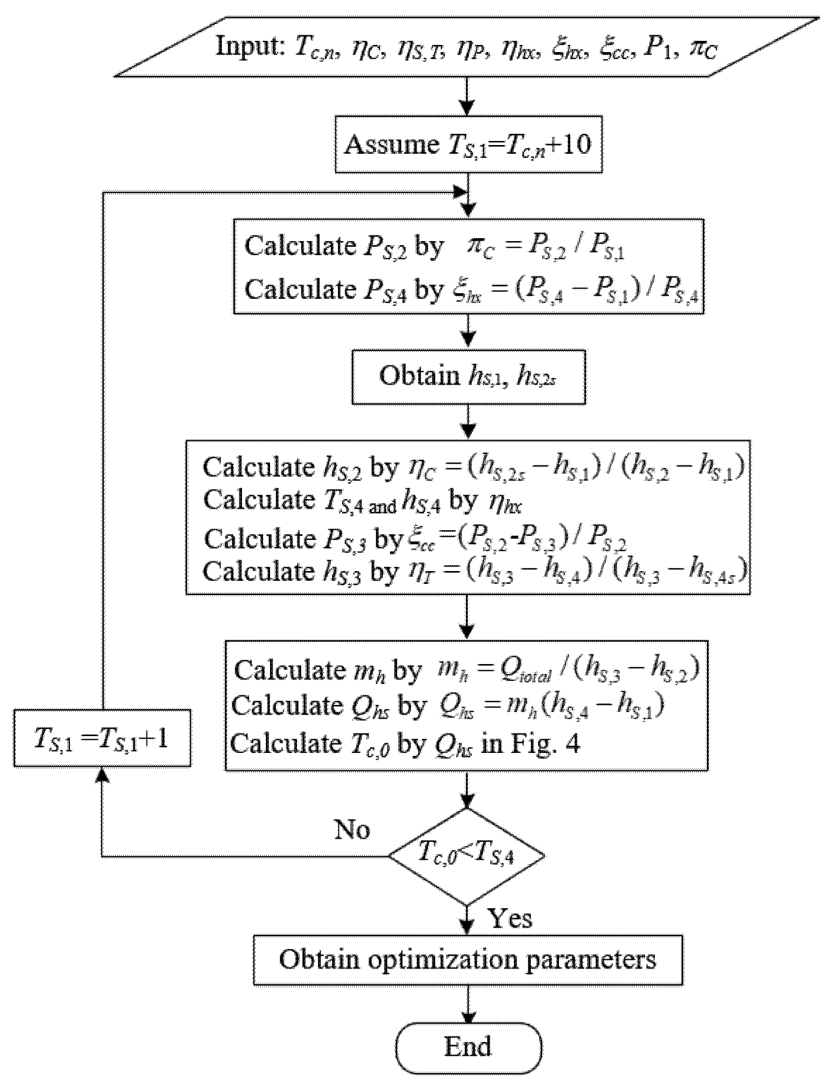
Figure 6. Preliminary optimization solution set and the example point of PTMS.
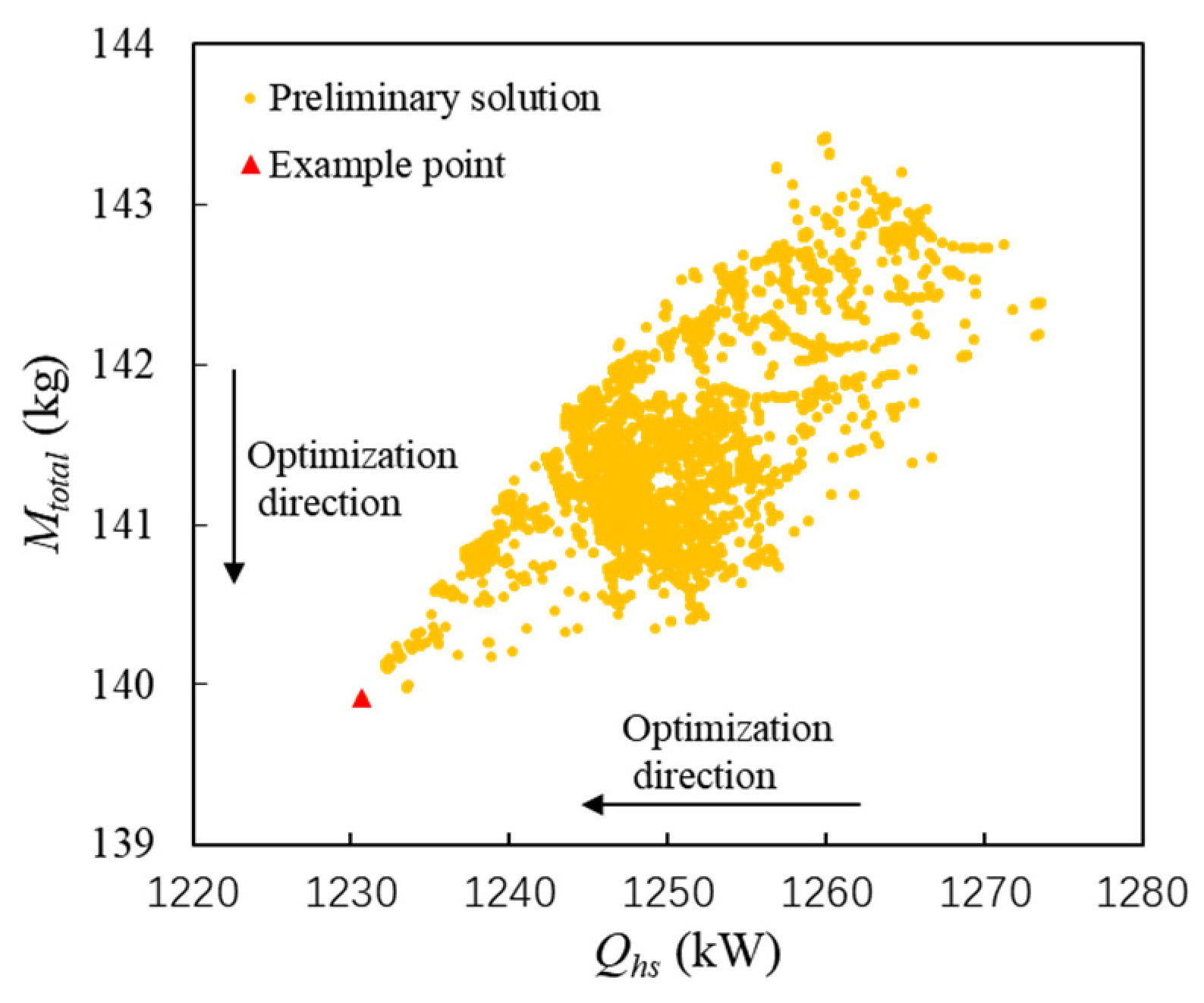
Figure 7. Heat exchange process of example point. (a) Variation curve of water equivalent with the temperature. (b) Temperature variation curve of sub-heat exchanger.
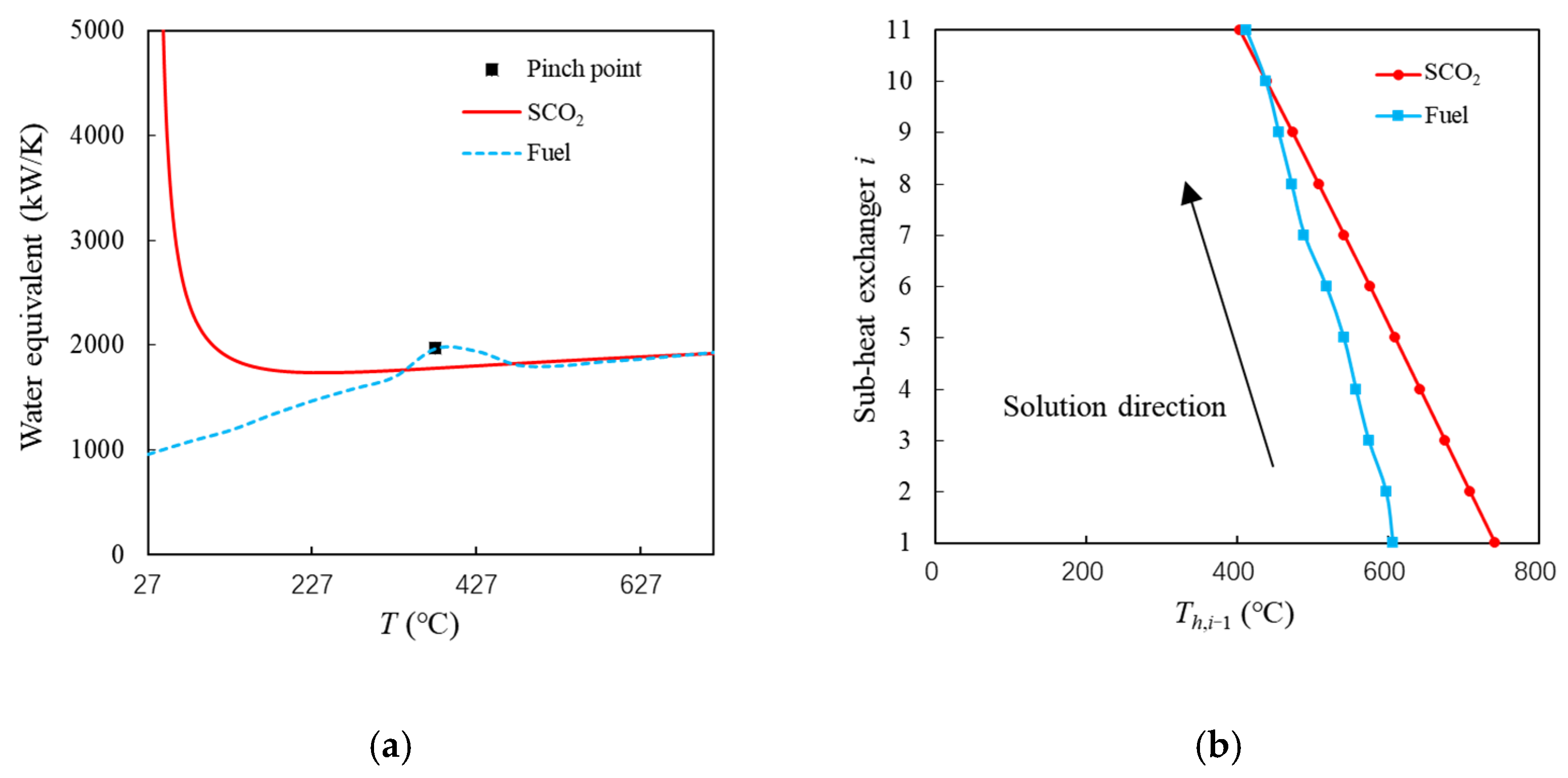
Figure 8. System-level optimization results after feasible selection with SEG method.
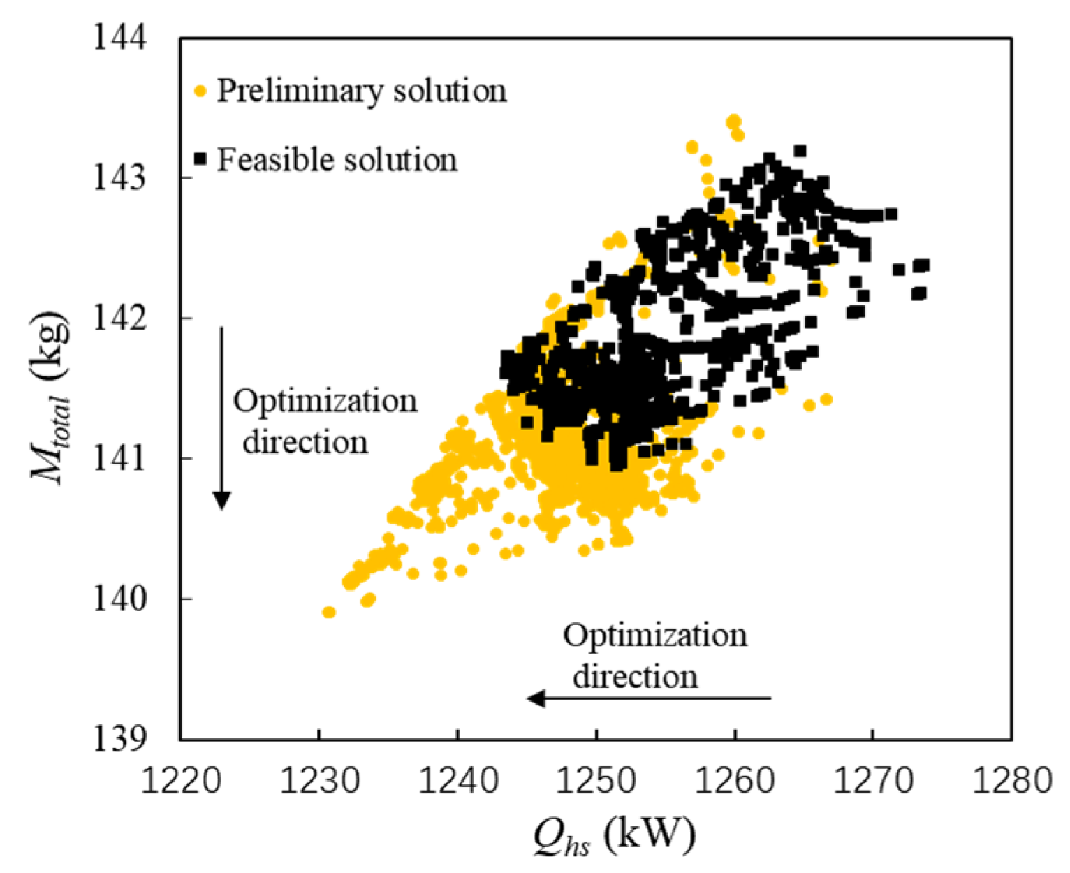
Figure 9. Relationship of Th,0, ηhx and Qhs in feasible solutions. (a) Hot side inlet temperature boundary (b) Efficiency boundary.
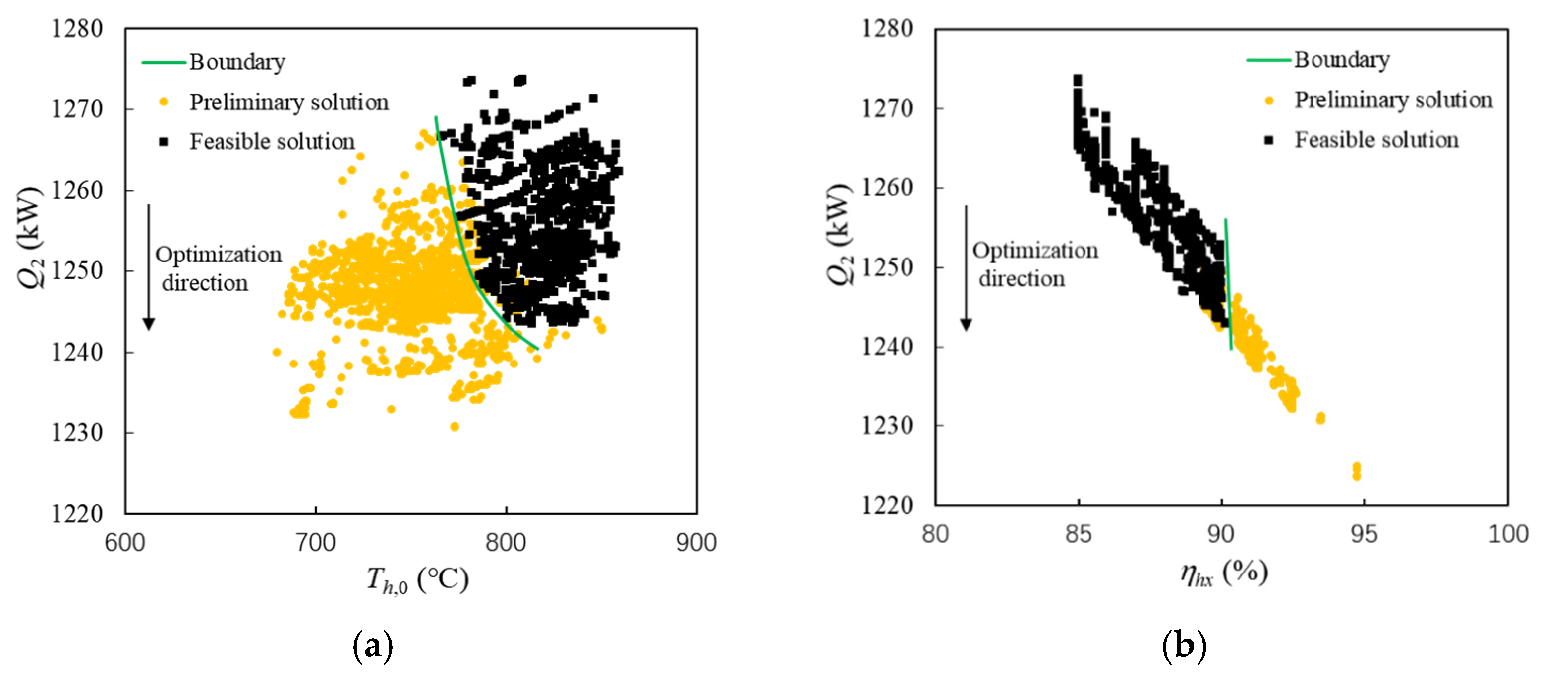
Figure 10. System-level optimization results.
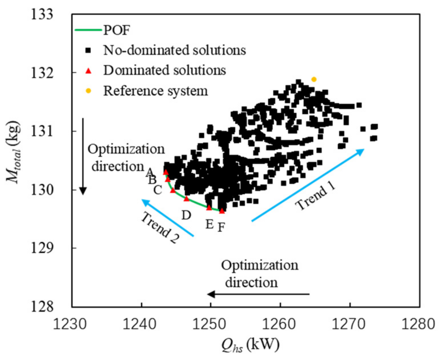
Figure 11. Relationships between optimization variables and optimization objectives. (a) πC and Qhs (b) πC and Mtotal. (c) P1 and Qhs (d) P1 and Mtotal. (e) ηhx and Qhs (f) ηhx and Mtotal.
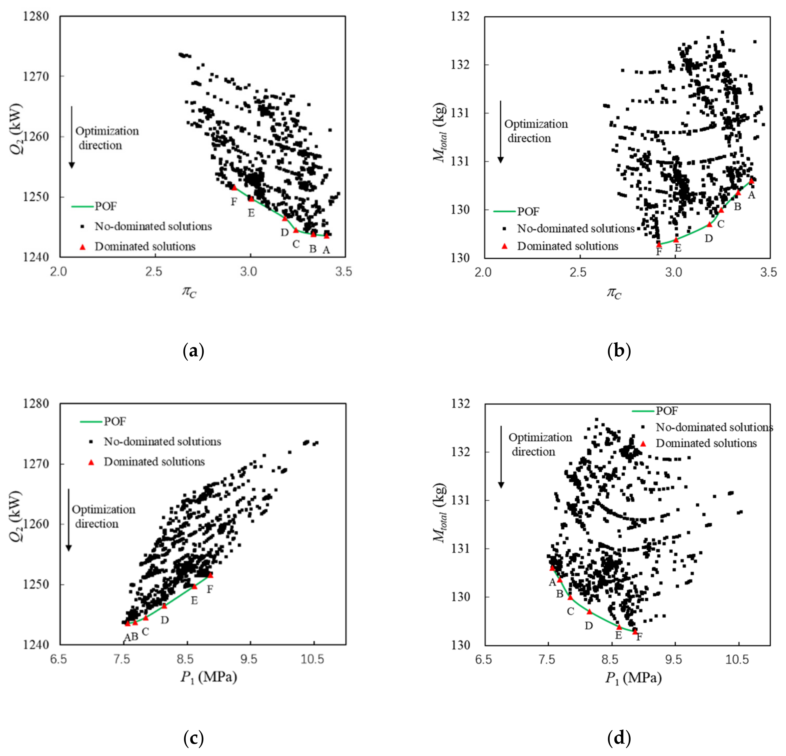
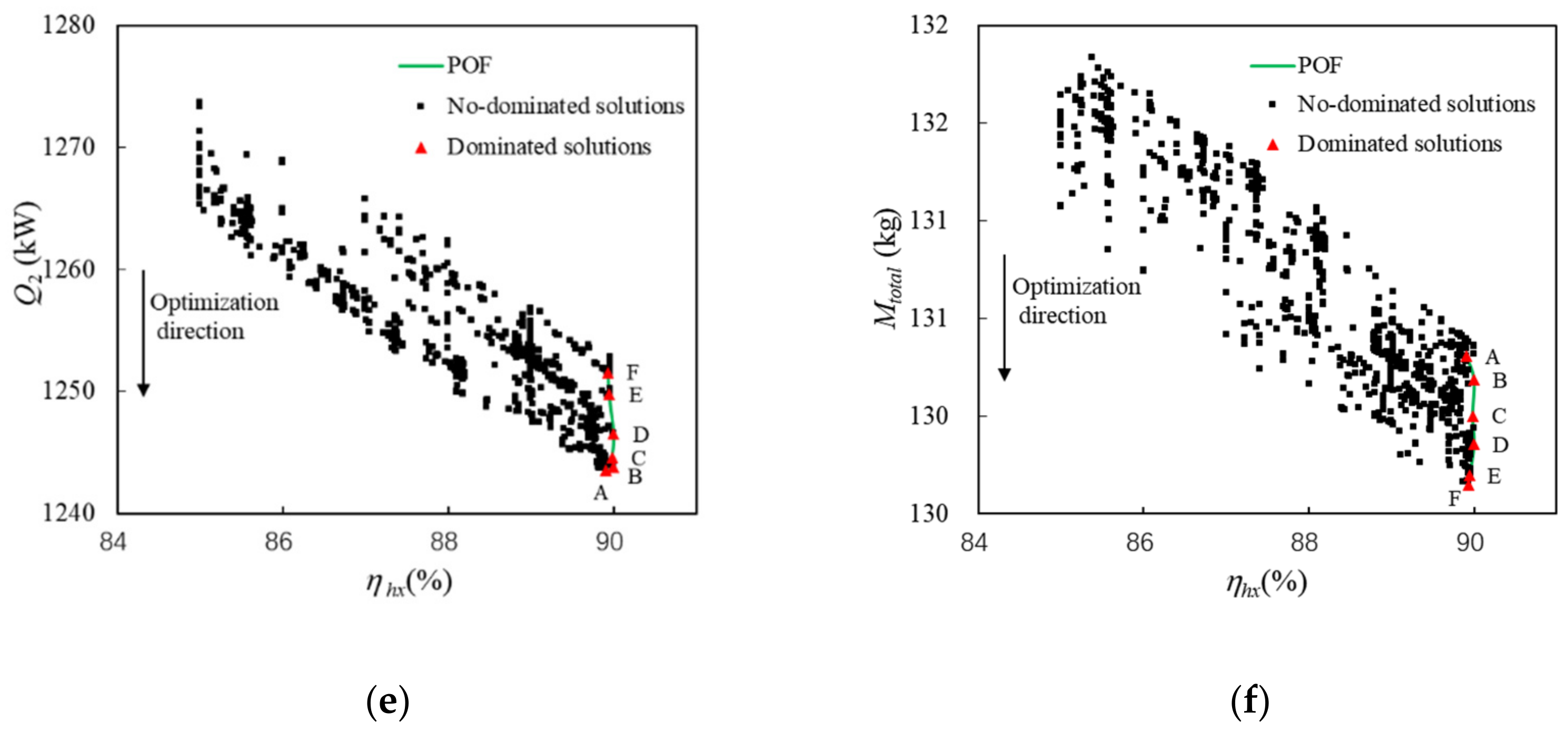
Figure 12. Component-level optimization results.
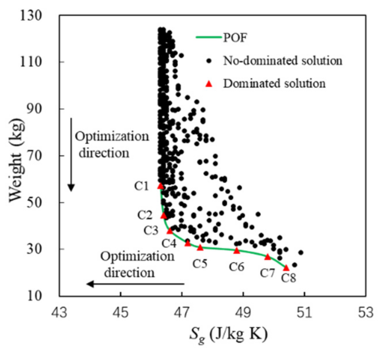
Figure 13. The relationship between SgP and SgT.
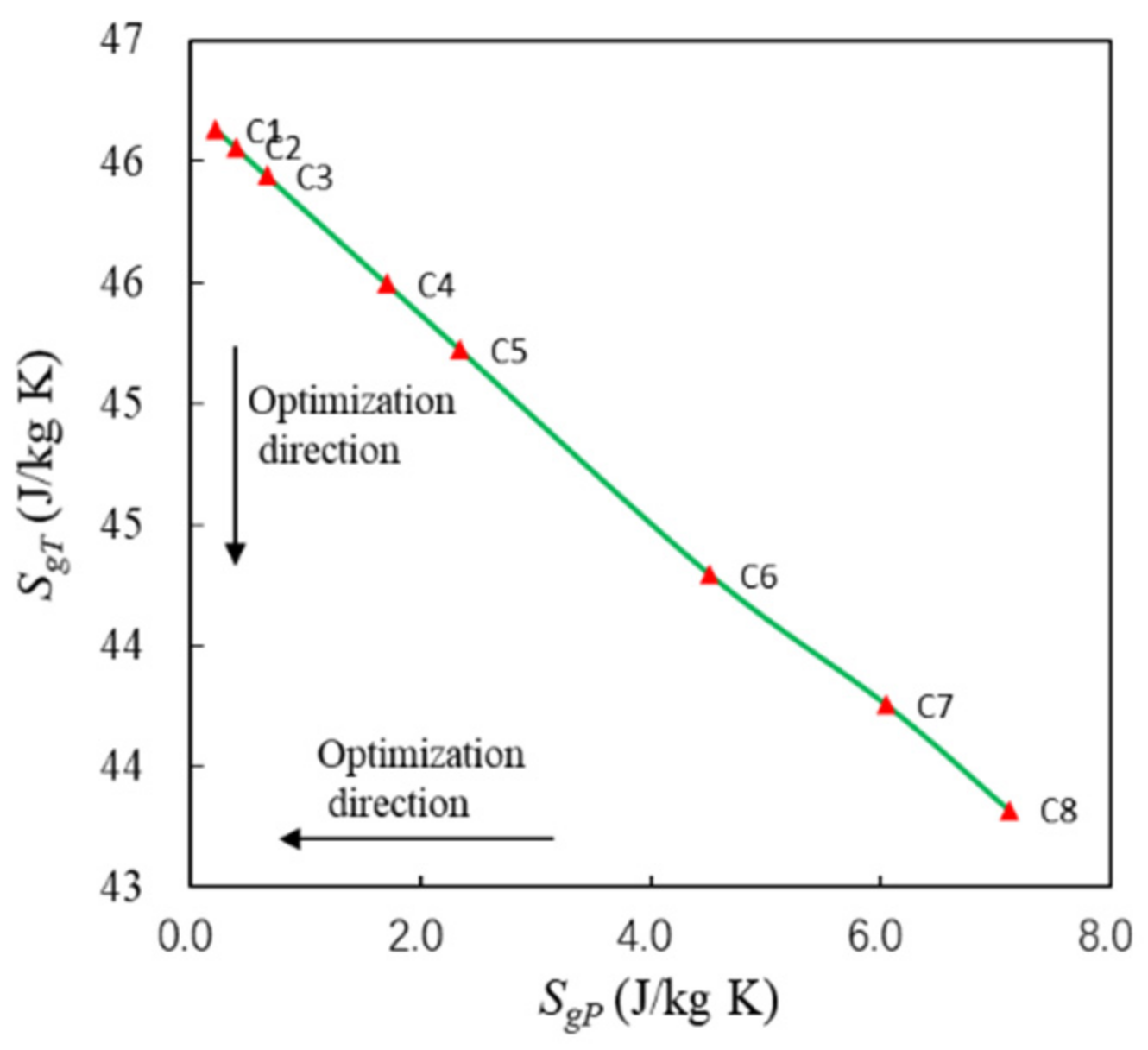
Figure 14. The fuel weight penalty of each component.
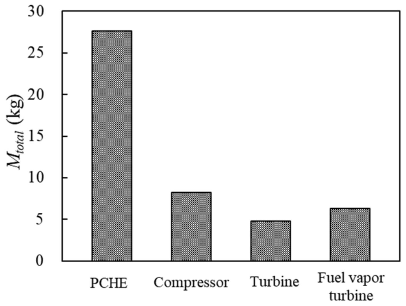
Figure 15. Comparison of optimization results.
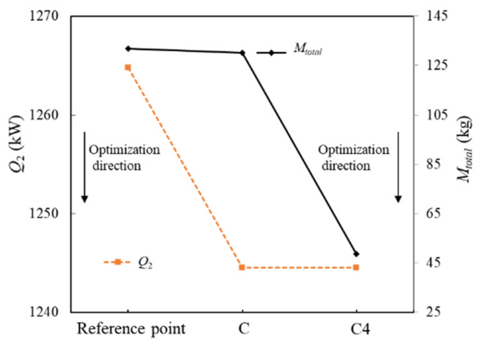
Table 1. Basic parameters of optimization.
| Parameter | Value |
|---|---|
| Flight speed (Ma) | 6 |
| Flight height (H) | 22 km |
| Fuel mass flow rate for combustion (ṁc) | 0.5 kg/s |
| The inlet temperature of the cold side of PCHE (Tc,n) | 50 °C |
| The outlet temperature of the cold side of PCHE (Tc,0) | 500~680 °C |
| Specific speed of compressor and fuel vapor turbine (Ns) | 0.4 |
| The efficiency of the compressor (ηC) | 0.9 |
| The efficiency of fuel vapor turbine (ηfT) | 0.75 |
| The efficiency of the turbine in the SCO2 cycle (ηST) | 0.9 |
| The efficiency of the fuel pump (ηP) | 0.7 |
| The efficiency of the generator (ηG) | 0.9 |
| Pinch temperature difference (ΔTmin) | ≥10 °C |
| The initial power-to-weight ratio of PCHE (PWR) | 10 |
| Maximum temperature of SCO2 cycle (Tmax) | <1000 |
| Relative pressure loss coefficient of PCHE (ξhx,s) in system-level optimization | 2% |
| Maximum relative pressure loss coefficient of PCHE (ξhx) | 2% |
| Maximum relative pressure loss coefficient of cooling channels (ξcc) | 2% |
| Heat dissipated from the scramjet wall at Mach 6 (Qtotal) | 1350 kW |
| Lift–drag ratio | 2.95 |
| TSFC (s−1) | 0.001 |
| Inlet pressure of the cold side of PCHE (Pc,n) | 5 MPa |
| Inlet pressure of fuel pump (Pp,in) | 0.1 MPa |
| Flight duration | 1 h |
| Pressure drop ratio of fuel vapor turbine (πfT) | 3 |
| Compressor inlet pressure (PS1) | ≥7.4 MPa |
| Compressor pressure ratio (πC) | 2~5 |
Table 2. Scheme process of the SEG method.
| Step | Process |
|---|---|
| 1 | Initialize parameters |
| 2 | Let i = 1 and assume Pc,0 |
| 3 | Calculate the average temperature and pressure of the segment |
| 4 | Calculate the thermodynamic properties of SCO2 [41] and fuel [11] |
| 5 | Calculate Rei, fi, Nui, Li, Pc,i, Tc,i, Ph,i, and Th,i |
| 6 | Let i = i + 1. If i ≤ n, then return to Step 3, otherwise, proceed to the next step |
| 7 | Calculate Ploss. If Ploss ≥ 2%, then return to Step 2, otherwise proceed to the next step |
| 8 | Calculate Th,I, Tc,i, L, M, PWR, ηhx, Sg, and end the process |
Table 3. Verification of turbomachinery model.
| Component | Rotation Speed (rad/min) | ṁh (kg/s) | Inlet Temperature (K) | Inlet Pressure (MPa) | πC/πT | Impeller Diameter (mm) | ||
|---|---|---|---|---|---|---|---|---|
| Experiment | Simulation | Difference (%) | ||||||
| Compressor | 75,000 | 3.5 | 305 | 7.7 | 1.8 | 18.7 | 19.2 | 2.7 |
| Turbine | 45,000 | 8 | 392 | 13.5 | 1.8 | 73 | 69.6 | 4.7 |
Table 4. Experimental parameters of PCHE.
| Parameter | L (mm) | wc (mm) | dc (mm) | tp (mm) | tf (mm) | Tc,n (K) | Pc,n (MPa) | Ph,0 (MPa) | mc/mh (kg/s) | Number of Channels, N |
|---|---|---|---|---|---|---|---|---|---|---|
| Value | 150 | 0.4 | 0.225 | 0.48 | 0.2 | 295 | 3 | 2.6 | 0.01 | 2400 |
Table 5. Verification of heat exchanger model.
| Th,0 (K) | ηhx (%) | ||
|---|---|---|---|
| Experiment | Simulation | Difference (%) | |
| 400 | 88.2 | 86.7 | 1.7 |
| 412 | 89.4 | 88.0 | 1.6 |
| 432 | 90.0 | 87.6 | 2.7 |
| 452 | 90.0 | 89.2 | 0.9 |
Table 6. System parameters of Pareto points.
| Pareto Point | ηhx (%) | P1 (MPa) | πC | (Kg/s) | Ph (MPa) | Th,0 (°C) | Tc,n (°C) | Qhs (kW) | Mtotal (kg) |
|---|---|---|---|---|---|---|---|---|---|
| A | 89.9 | 7.5 | 3.4 | 1.52 | 7.6 | 813.8 | 616.8 | 1243.6 | 130.3 |
| B | 90.0 | 7.6 | 3.3 | 1.53 | 7.7 | 812.5 | 616.9 | 1243.8 | 130.2 |
| C | 90.0 | 7.7 | 3.2 | 1.55 | 7.8 | 801.2 | 617.1 | 1244.6 | 130.0 |
| D | 90.0 | 8.0 | 3.2 | 1.56 | 8.1 | 797.3 | 617.3 | 1246.5 | 129.9 |
| E | 89.9 | 8.5 | 3.0 | 1.54 | 8.6 | 799.2 | 617.8 | 1249.8 | 129.7 |
| F | 89.9 | 8.8 | 2.9 | 1.54 | 8.9 | 801.3 | 618.0 | 1251.6 | 129.6 |
Table 7. Parameters of C1~C8.
| Pareto Point | wc (mm) | W (m) | H (m) | L (m) | Weight (kg) | SgT (J/kg·K) | SgP (J/kg·K) | Sg (J/kg·K) | Ploss (%) | Efficiency (%) | PWR | Volume (cm3) |
|---|---|---|---|---|---|---|---|---|---|---|---|---|
| C1 | 1.1 | 0.15 | 0.27 | 0.72 | 57.2 | 46.1 | 0.2 | 46.3 | 0.05 | 89.83 | 21.8 | 28,458 |
| C2 | 1.0 | 0.21 | 0.16 | 0.70 | 44.7 | 46.1 | 0.4 | 46.4 | 0.08 | 89.83 | 27.9 | 22,214 |
| C3 | 1.0 | 0.10 | 0.25 | 0.73 | 38.1 | 45.9 | 0.7 | 46.6 | 0.14 | 89.83 | 32.7 | 18,925 |
| C4 | 1.0 | 0.26 | 0.07 | 0.95 | 32.7 | 45.5 | 1.7 | 47.2 | 0.36 | 89.84 | 38.0 | 16,285 |
| C5 | 1.0 | 0.07 | 0.20 | 1.02 | 30.9 | 45.2 | 2.3 | 47.6 | 0.49 | 89.85 | 40.3 | 15,354 |
| C6 | 1.0 | 0.08 | 0.14 | 1.27 | 29.6 | 44.3 | 4.5 | 48.8 | 0.95 | 89.87 | 42.1 | 14,711 |
| C7 | 1.1 | 0.08 | 0.12 | 1.43 | 26.9 | 43.8 | 6.1 | 49.8 | 1.24 | 89.88 | 46.3 | 13,371 |
| C8 | 1.0 | 0.10 | 0.09 | 1.28 | 22.2 | 43.3 | 7.1 | 50.4 | 1.46 | 89.89 | 56.2 | 11,025 |
Table 8. Weight and dimensional design of turbomachinery.
| Parameter | Compressor | Turbine in SCO2 Cycle | Fuel Vapor Turbine |
|---|---|---|---|
| Ns | 0.4 | 0.51 | 0.4 |
| Rotation speed in optimal working condition (rad/min) | 10,778 | 10,778 | 5761 |
| Impeller diameter (mm) | 226 | 173 | 197 |
| Weight (kg) | 9.3 | 5.4 | 7.1 |
Publisher’s Note: MDPI stays neutral with regard to jurisdictional claims in published maps and institutional affiliations. |
© 2022 by the authors. Licensee MDPI, Basel, Switzerland. This article is an open access article distributed under the terms and conditions of the Creative Commons Attribution (CC BY) license (https://creativecommons.org/licenses/by/4.0/).
Share and Cite
MDPI and ACS Style
Guo, L.; Pang, L.; Zhao, J.; Yang, X. Optimization of Power and Thermal Management System of Hypersonic Vehicle with Finite Heat Sink of Fuel. Energies 2022, 15, 5332. https://doi.org/10.3390/en15155332
AMA Style
Guo L, Pang L, Zhao J, Yang X. Optimization of Power and Thermal Management System of Hypersonic Vehicle with Finite Heat Sink of Fuel. Energies. 2022; 15(15):5332. https://doi.org/10.3390/en15155332
Chicago/Turabian Style
Guo, Liang, Liping Pang, Jingquan Zhao, and Xiaodong Yang. 2022. "Optimization of Power and Thermal Management System of Hypersonic Vehicle with Finite Heat Sink of Fuel" Energies 15, no. 15: 5332. https://doi.org/10.3390/en15155332
Note that from the first issue of 2016, this journal uses article numbers instead of page numbers. See further details here.
Heat Management in Supersonic/Hypersonic Vehicles Using Endothermic Fuel: Perspective and Challenges
1. Introduction
Click to copy section linkSection link copied!
Thermal resource management (TRM) of onboard hypersonic vehicles is an important field of research and development, and considerable attention has been received from the scientific community in the past few decades. Rockets are considered a high-speed propulsion vehicle, which is limited by its ratio of lower thrust to the mass of fuel burnt. The thrust-to-fuel burnt ratio is generally higher for a turbo engine due to its inherent design. A supersonic combustion ramjet (scramjet) is an advanced propulsion engine that usually works in high Mach number regions (>Mach 4) and provides power for hypersonic air-breathing vehicles. With the increase in Mach number, the intake air temperature becomes too high to cool the engine structure. A scramjet engine at hypersonic speed warrants stringent cooling requirements to manage its thermal load. A regenerative cooling using onboard fuel could be an effective thermal management method. (1) The idea of regenerative cooling is to transfer heat from the hot engine to the cold hydrocarbon fluid. In a regenerative cooling process, the fuel temperature increases gradually, and eventually, it reaches a temperature that triggers endothermic chemical reactions. (2) The concept of endothermic fuel development is not new, and many researchers are trying to develop it still today. Scientists are of the common opinion that coke formation and its accumulation in the fuel line are two of the critical constraints for regenerative cooling using hydrocarbon fuels.
The heat absorbed by the fuel is moderate at a low Mach number, and the fuel exists in a liquid state. With the increase in vehicle speed, the temperature of the aerothermal environment would increase. Consequently, the fuel temperature in the regenerative cooling channel rises, and beyond a specific temperature, the fuel can undergo a pyrolysis reaction. Usually, the sensible heat of the fuel can suffice the cooling requirements of an engine up to Mach 3, and beyond this value, the cooling of an engine can be fulfilled through endothermic reactions. (3,4) In a few studies, regenerative cooling via endothermic reactions has been referred to as a chemical recuperative heat removal device. (5−7) In the presence of high thermal loads, hydrocarbons tend to break or crack into smaller hydrocarbon molecules. These thermally cracked products would be injected into the combustor as a fuel to fulfill supersonic combustion requirements like lower ignition times, superior burning rate, etc. (8,9)
Therefore, managing thermal loads in an advanced engine to power future aircraft/engines is challenging. In practice, when an engine approaches hypersonic speeds, the temperature of the air entering into the combustion chamber is too high. An X-51 waverider and similar flight engines are designed to operate at a high pressure (typically 250 to 300 times higher than the ambient pressure) and high fuel-to-air ratio (about 0.05 to 0.06), which significantly manifolds the heat loads and worsens thermal management. (10) Hence, thermal management has turned out to be a key concern in the development of scramjet engines. Therefore, to fulfill the high energy output and high heat sink capability, specific hydrocarbon fuels can be chosen to substitute conventional solid propellants or hypergolic fuels along with oxidizers. Research and development groups are of the common opinion that active and spontaneous cooling could be a better approach than providing passive cooling like thermal protection of the scramjet engine. Significant research has been carried out to understand hydrocarbon fuel cracking behavior at elevated temperatures and pressures. Most investigations have been carried out under supercritical conditions using small-diameter (<5 mm) tubular reactors. Hydrocarbon fuels such as JP-8, RP-1, RP-3, JP-7, JP-900, JP-10, n-heptane, n-decane, and n-dodecane have been chosen for experimental studies by the majority of authors.
The present paper summarizes the effects of various parameters like fuel flow rate, reactor pressure, temperature, fuel composition on cracking conversion, heat sink capacity, and coke propensity. For the benefit of the readers, the present paper has been subdivided into different sections with specific objectives and outcomes. The major technoengineering aspects covered in the present paper are as follows: (i) physicochemical characteristics of different endothermic fuels, (ii) pyrolysis of endothermic fuels, (iii) catalytic cracking of endothermic fuels, (iv) phenomena of coking during cracking, (v) influence of additives on suppression of coking, and (vi) suitability of initiators to improve the endothermicity of hydrocarbon fuels. The critical outcomes of individual sections are briefed with necessary figures and tables. Finally, the salient features of each section are summarized along with the perspective and conclusions. The present work mainly emphasizes the engineering and application aspects of fuel cracking under supercritical or near-critical conditions and not the fundamental chemistry of hydrocarbon cracking under subcritical conditions.
2. Physicochemical Characteristics of Various Jet Fuels
Click to copy section linkSection link copied!
Various types of jet propellants (e.g., JP-7, JP-8, RP-1, and RP-3) are commonly used for supersonic applications due to their excellent combustion quality, low coke deposition, and high energy density. However, due to high production costs and limitations for hypersonic applications, the development of an alternative/modified fuel has become an important research area across the globe. From a plethora of literature, it has been found that many research groups have studied the suitability of modified JP-7- and JP-8-equivalent fuels for hypersonic applications.
Lovestead and Bruno (11) and Smith and Bruno (12) have investigated the boiling characteristics and composition of different grades of jet fuels. The ASTM D86 distillation characteristics of representative JP-7 and JP-8 fuels are shown in Table 1. The initial boiling point (IBP) of JP-7 is relatively higher than that of JP-8, which indicates the better thermal stability of JP-7. The major hydrocarbon contents in JP-8 are in the range between C7 and C14, whereas for JP-7, the major hydrocarbons lie between C8 and C14.
Table 1. Distillation Characteristics of JP-7, JP-8, RP-3, JP-900, and Jet Fuelsa
Song et al. (13) have studied the physicochemical characteristics of coal-derived JP-8C fuel. The fuel was prepared by coal gasification followed by a hydrotreating process. The density of JP-8C is relatively higher than that of a petroleum-derived JP-8 fuel, and the fuel consists of more than 75 wt % cycloalkanes and about 20 wt % aromatics. The study concluded that the JP-8C fuel was more stable (thermally) than a petroleum-derived JP-8 fuel at 450 °C. Balster et al. (14) have studied the fouling characteristics of synthetic aviation kerosene fuel. The fuel was derived from coal and was almost free from aromatics, sulfur, and nitrogen compounds. The pour point, flash point, and specific gravity of the fuel were relatively higher than the fuel specifications laid down for military applications.
Li et al. (7) have examined the combustion characteristics of JP-10 fuel. It is a single-component (tricyclodecane) synthetic fuel consisting of 99% cycloparaffins. The average boiling point and °API gravity of the fuel are 192 °C and 19.1, respectively. The combustion energy of JP-10 is around 39 MJ/L. Balster et al. (15) have studied the suitability of coal-derived JP-900 fuel for heat sink capability in a propulsion engine. The fuel was prepared by blending an equal volume of coal-derived refined chemical oil (RCO) and petroleum-derived light cycle oil (LCO), followed by a hydrotreating process. The boiling range and specific gravity of the blended fuel are 180–267 °C and 0.87, respectively. The fuel was thermally stable up to 480 °C, and it consists of more than 50 vol % decalin hydrocarbon. The polar species content in the fuel was around 22 mg/L, whereas for typical jet fuels, the corresponding value is in the range of 100 to 600 mg/L. The amount of coke deposition of JP-900 was 10 times less than a JP-8 fuel under similar test conditions. Bruno and Smith (16) have studied the distillation and compositional characteristics of RP-1 fuel.
A comparison of ASTM D86 distillation characteristics of various jet fuels is shown in Figure 1, and the details are mentioned in Table 1. The data indicates that JP-7 is relatively a narrow cut fuel, and for jet fuel, the boiling range is maximum among the six fuels. The estimated values of the average boiling point of JP-7, JP-8, RP-1, RP-3, and JP-900 fuels are 219, 199, 213, 203.7, and 207.3 °C, respectively.
Figure 1

Figure 1. ASTM D86 distillation data of various hydrocarbon fuels.
The nature of hydrocarbon and its amount in a fuel play a vital role in offering a specific heat sink capacity. DeBlase et al. (17) have examined the effects of aliphatic versus aromatic content on the composition of an endothermic fuel using in situ mass spectroscopy. The smaller aromatics and their methyl-substituted derivatives showed a higher tendency to form larger polycyclic aromatic hydrocarbons (PAHs), a precursor for coke formation at the highest temperatures. Various properties such as the hydrocarbon composition, °API gravity, sulfur content, and boiling range of different jet fuels are summarized in Table 2. The information is helpful in analyzing and correlating various thermal characteristics, e.g., thermal stability, coke propensity, and cracking conversion. The paraffin content in JP-7 is relatively higher than that in a JP-8 fuel. However, the aromatic content in JP-8 is about four times higher than that in a JP-7 fuel. The presence of cyclic and heteroatomic species is of significant concern for coke and gum propensity during a thermal cracking process.
Table 2. Various Properties of JP-7, JP-8, RP-1, RP-3, JP-900, and Norpar-12 Fuels
3. Thermal Cracking Characteristics of Endothermic Hydrocarbon Fuels
Click to copy section linkSection link copied!
The concept of endothermic hydrocarbon fuel has received significant attention from the academic community due to its higher energy density and higher heat sink capacity. Although hydrogen is considered one of the best endothermic fuels, safe handling and logistics to maintain it as a liquid are significant concerns. The logistics are even more critical for an onboard space vehicle due to space and weight constraints. Several engineering issues related to quick combustion and flame stabilization in a supersonic vehicle are other critical issues. Several researchers have proposed using hydrocarbon fuel as endothermic fuel with proper control of cracking reactions in a desirous way to enhance the cooling efficiency of a hypersonic engine. Several methods, such as thermal cracking, catalytic cracking, depolymerization, and dehydrogenation, can be employed to absorb the additional heat loads to manage the thermal load of combustion engines. (25−29) Two dominant factors, namely, fuel cracking conversion and the distribution of cracked species patterns, are crucial to reducing the extent of thermal load. Combustion quality is related to cracked products at the cooling channel end, whereas fuel conversion and product composition are related to the heat sink capacities.
Daniau and Sicard (30) have developed a global kinetic model to predict product composition from thermal cracking of long-chain saturated hydrocarbons(CnH2n+2). Norpar-12 fuel (a mixture of C9 to C12 hydrocarbons) was used to develop the kinetic model, and the model was validated with an n-dodecane (C12H26) hydrocarbon in the temperature range between 380 and 1225 °C and pressures up to 100 bar. The authors claimed that the model-predicted data matched well with the experimental data for methane, ethane, and other major alkenes except for ethylene. However, the authors have not disclosed the details of the model parameters in the article. Ning et al. (31) have reported that the propagation of cracking reaction via a free radical mechanism favored the increase in paraffin-to-olefin ratio beyond the critical pressure of hydrocarbons. However, the generated olefins can undergo further reactions to form alkanes at elevated temperatures and pressures. The addition reaction is being exothermic, leading to a decrease in the overall heat sink capacity. The authors have also mentioned that beyond the critical pressure of the fuels, the rupture of five- and six-membered cyclic compounds reduced drastically and converted into cyclic isomers that act as an active precursor for coke formation.
The operating variables such as temperature, pressure, residence time, etc., play an important role in cracking. The simulation of cracking products from multicomponent fuels under a supercritical environment is a challenging task. The variation in chemical composition and the thermophysical properties of the fluid along the flow path need to be considered to obtain more realistic and accurate results. In many studies, researchers have used surrogate fuel to reduce complexity and understand the pyrolysis mechanism. Most authors have estimated the heat sink value of an endothermic fuel by measuring the fluid inlet and outlet temperatures and assuming that the fluid composition largely remains constant between the reactor inlet and the outlet. The chemical or endothermic heat sink value was obtained by subtracting the sensible heat from the total heat input. The expressions used by different authors to estimate the endothermic heat sink value of various fuels are shown below. (32)

(1)

(2)

(3)

(4)
NIST SUPERTRAPP software was used in many studies to estimate the physicochemical properties of fuels under elevated temperature and pressure conditions. The Peng–Robinson equation of state and extended corresponding states (EXCST) are used in the software for phase equilibrium calculations to generate thermophysical properties of various systems. The software consists of around 210 components along with their properties. Jackson et al. (33) studied the heat sink capacity of JP-7 fuel using an indigenous engine system similar to a hypersonic scramjet engine. The estimated value of the total heat absorption capacity of the fuel is around 4000 kJ/kg at 700 °C and 24 bar pressure. However, the heat loss quantity and the endothermic heat sink capacity of the fuel are not reported. Jin et al. (34) studied the thermal cracking characteristics of RP-3 fuel at different values of pressures and temperatures. The experiments were carried out in the temperature and pressure ranges of 500–750 °C and 7–60 bar, respectively. The study showed that the feed conversion and endothermic heat sink capacity increased with both pressure and temperature. The alkene selectivity decreased with pressure, thereby affecting the chemical heat sink capacities.
The thermal cracking behavior of n-octane, JP-7, and JP-8+100 fuels under elevated temperature and pressure conditions has been investigated by Huang et al. (32) The experiments were performed in a test rig consisting of a combustor, heat exchanger, and liquid-vapor nozzle systems. The study was carried out in the temperature range of 700–815 °C and under 23 bar pressure. The reported values of total heat sink capacity of n-octane, JP-7, and JP-8+100 fuels are 3279, 3233, and 2954 kJ/kg, respectively, at 703 °C and 23.4 bar pressure. Heinrich et al. (35) have conducted an in-depth study on endothermic cracking of Norpar-12 and n-dodecane to investigate the heat sink capacity. A tubular reactor was used to carry out the cracking experiments at a temperature range of 627 to 1027 °C and a pressure range of 25 to 35 bar. The estimated values of the total heat sink capacity of Norpar-12 and n-dodecane fuels are 2750 and 2590 kJ/kg, respectively, at 647 °C. The authors claimed that the estimated value of the heat sink is sufficient to meet the thermal management requirements for a hypersonic vehicle at Mach 5 speed.
Jiang et al. (36) investigated the heat sink of kerosene range fuel (HF-1) under supercritical conditions using a flow reactor. The total heat sink capacity of the fuel is about 3045 kJ/kg at 680 °C and 50 bar. Zhu et al. (37) performed the endothermic cracking of n-decane and the estimated value of the total heat sink capacity of n-decane is around 2700 kJ/kg at 667 °C and 40 bar pressure. Chakraborty and Kunzru (38) have studied the thermal cracking behavior of n-heptane at a temperature range of 640–680 °C under subcritical pressure conditions. The conversion of n-heptane and alkane selectivity increased with the increase in pressure, while the selectivity of lighter olefins decreased with pressure. Pan et al. (39) have studied the pyrolysis of JP-10 fuel in a nickel-coated tubular reactor at 45 bar pressure. The total heat sink capacity value is around 2600 kJ/kg of the fuel at 730 °C for 60 g/min feed flow rate. The coke deposition on the reactor surface was about 100 times lower than the coke obtained from the downstream filter.
The thermal cracking mechanism is quite complex. Generally, three main types of thermal reaction models, namely, detailed, lumped, and global mechanisms, are mentioned in some literature. Although there are many articles on the mechanism of hydrocarbon cracking under sub- and supercritical environments, the mechanistic chemistry is kept aside from the present study to focus more on technoengineering aspects on endothermic fuel development. Ward et al. (40) have investigated the thermal cracking of n-decane and n-dodecane under high-pressure conditions using a tubular flow reactor. The reactor pressure and temperature were varied between 34 and 114 bar and between 550 and 600 °C, respectively, with a lower value (∼0.5 mL/min) of fuel flow rate. Based on two-dimensional CFD simulation, the authors proposed the “Proportional Product Distribution” (PPD) model to describe the product pattern under mild (conversion < 20%) thermal cracking situation and validated it with experimental data. The study also demonstrates that increasing pressure was beneficial for bimolecular reactions and the overall conversion because of residence time increased. However, the effect of pressure on carbon deposition is not emphasized. Goel and Boehman (41) demonstrated the use of modeling for the thermal degradation of n-dodecane and Norpar-13 using a flow reactor. A one-step global model is proposed to describe the pyrolysis of jet fuels under high-pressure conditions. The study showed that the outlet temperature and fuel degradation decreased with the increase in fuel flow rate. For high temperatures, the simulation was performed by extrapolating the batch reactor kinetics obtained at 460 °C.
The total heat sink capacity of different hydrocarbon fuels is shown in Figure 2, along with operating temperature and pressure. The value of total heat sink capacity of various fuels ranges between 2500 and 3200 kJ/kg for a temperature range of 600 to 750 °C. A summary of the total and endothermic heat sink capacities of various hydrocarbon fuels at different temperatures and pressures is shown in Table 3. The endothermic heat sink capacity of various fuels ranges between 500 and 1200 kJ/kg of fuel. Based on the reported data, it can be said that the heat sink capacity of hydrocarbon fuels depends on many parameters like fuel composition, nature of hydrocarbon, fuel flow rate, and operating temperature and pressure. The data also revealed that in most cases, the total (physical and chemical combined) heat sink value is three to four times higher than the corresponding endothermic (chemical) heat sink value.
Figure 2

Figure 2. Total heat sink capacity of various hydrocarbon fuels for ranges of temperature of 650–750 °C and pressure of 24–60 bar.
Reprinted (adapted or reprinted in part) with permission from refs (32,34−37) and (39). Copyright 2004 The American Society of Mechanical Engineers, 2017 Elsevier, 2001 American Institute of Aeronautics and Astronautics, Inc., 2014 American Chemical Society, and 2020 American Chemical Society.
Table 3. Total and Endothermic Heat Sink Capacities of Various Fuels
4. Supercritical Catalytic Cracking of Endothermic Hydrocarbon Fuels
Click to copy section linkSection link copied!
Catalytic cracking of hydrocarbons is carried out to improve fuel quality and olefin selectivity in cracked products. Generally, a catalytic cracking process required a lower severity operation compared to the thermal cracking process for a similar extent of cracking. The catalyst selection is vital for a specific feed to obtain maximum benefits from a catalytic cracking process. (42) Although many articles are available on the catalytic cracking of hydrocarbons, very few of them are related to the current topic, i.e., supercritical catalytic cracking of endothermic fuels.
Zhang et al. (43) have studied the catalytic cracking of NNJ-150 (a mixture of C9 to C17 hydrocarbons) fuel in the presence of Ag- and La-impregnated silica–alumina-based USHY, HZSM, and SAPO-34 catalysts. In the presence of catalysts, the fuel conversion increased by more than 2-fold in comparison to the thermal cracking under similar operating conditions. The estimated values of feed conversion in the presence of USHY, HZSM, and SAPO-34 are 75, 76, and 53%, respectively, at 500 °C. Xian et al. (44) studied the cracking characteristics of n-dodecane in the presence of HZSM-5. The study was performed in the temperature and pressure ranges of 400–450 °C and 16–40 bar, respectively, using a fixed-bed flow reactor. The dodecane conversion decreased with the increase in reactor pressure. The estimated values of fuel conversion at 16 and 40 bar pressures are 71 and 50%, respectively, at 450 °C with a catalyst-to-fuel ratio of 0.5 and 20 min run time. The coke yield at 450 °C and 40 bar was around 0.032 wt % with a 3 g/min feed flow rate. Huang et al. (45) studied the pyrolysis of JP-10 with zeolite Y using a fixed-bed reactor. The product distribution pattern for the catalytic cracking was significantly different from the thermal cracking without zeolite Y. It was observed that the endothermic capacity of the fuel for catalytic cracking was slightly less than that for pyrolytic cracking for similar levels of conversion.
Huang et al. (4) performed an exhaustive study on the endothermic cracking of JP-7, JP-10, and n-octane fuels over a zeolite-coated tubular reactor. The experiments were performed at 41 bar pressure for a duration of 15 min with a feed flow rate of 36.3 g/min. The amount of coke deposition was estimated by converting the coke into CO2, and the endothermicity of the fuel was calculated using SUPERTRAPP software. The estimated values of the coke formation rate for JP-7, JP-10, and n-octane are 0.94, 0.88, and 0.43 mg/min, respectively. Lander and Nixon (25) studied the thermal cracking of JP-7 fuel, and the estimated value of total heat sink capacity at 650 °C is about 2721 kJ/kg of fuel, which is insufficient to cool an engine operating above Mach 6 speeds. The team worked on single-component fuels such as JP-10 and methylcyclohexane (MCH) to improve the heat sink capacity. The heat sink was more than 4500 kJ/kg of fuel when a combined process of dehydrogenation and cracking was followed at 727 °C and 10 bar pressure in the presence of a Pt/Al2O3 catalyst. Although the heat sink number appears to be very attractive for the combined process, its implementation in actual hypersonic vehicles could be a significant challenge due to various reasons like the deposition of coke on the catalyst surface, coating of the catalyst layer inside the fuel line, maintaining of supercritical condition, etc.
Gao et al. (46) have studied the suitability of the Ni-doped Al2O3 catalyst for the suppression of coke during the cracking of RP-3 fuel. The experiments were performed at 680 °C and 30 bar pressure using a rectangular flow reactor in the presence of steam. The study claims that the catalytic steam reforming improved the chemical heat sink capacity by around 750 kJ/kg of RP-3 fuel. It is also highlighted that the presence of the catalyst and steam together reduced the coke deposition rate from 148 μg/(cm2·min) to 22.5 μg/(cm2·min). However, the individual effect of steam and the catalyst on heat sink capacity and coke deposition is not reported.
Yeh et al. (47) have studied the endothermic reforming of n-hexane on a Ga-promoted H-ZSM-5 catalyst under elevated pressures using a fixed-bed flow reactor. The experiment was carried out at 550 °C and 137 bar pressure with a feed flow rate of 0.3 mL/min. The catalyst was used in the form of a pallet. It is reported that the addition of Ga on H-ZSM-5 significantly increased the heat of reaction by increasing the selectivity of small aromatics. The reported value of n-hexane conversion is 9.5% at 550 °C and 137 bar. The study also reports that lighter olefin production decreased significantly at elevated pressures. Tian et al. (48) studied the effect of JP-10 cracking over HZSM-5 zeolites. The cracking performance on nanosheet zeolite was relatively better compared to bulk zeolite for the similar value of the Si/Al ratio due to the better accessibility of acid sites and reduced diffusion paths. The enhanced diffusion of JP-10 increased the olefin yields. Yeh et al. (49) have investigated the cracking of n-hexane at 500 °C and 60 bar pressure on a surface of HZSM-5 and Zn-HZSM-5 catalysts. The study reports that the reaction is mildly endothermic at low conversions of n-hexane (<120 kJ/kg) on HZSM-5, and at conversions above 50%, the reaction is exothermic. However, the Zn-HZSM-5 catalyst showed better endothermicity for a similar range of n-hexane conversion.
A summary of the endothermic heat sink capacity of various fuels in the presence of different catalysts is shown in Table 4. It has been observed that the operating temperatures in catalytic cracking studies are relatively higher than the thermal cracking temperatures. Also, this was possible due to a lesser amount of coke formation in the presence of a catalyst. Lower coke yield offered an extra cushion to increase the operating temperature and improve the endothermicity of fuels. Although catalysts can enhance the heat sink capacity of fuel, their demonstration in a hypersonic engine can be a significant challenge to engine designers and fabricators.
Table 4. Heat Sink Capacity of Hydrocarbon Fuels in the Presence of Different Catalysts
5. Phenomena of Coking during the Thermal Degradation of Hydrocarbon Fuels
Click to copy section linkSection link copied!
Coke and gum formation is a common phenomenon that occurs during the degradation and cracking of fuels. The coke deposition in a fuel flow line can create potential failure by blocking the fuel injection line. Coking is a primary concern for hydrocarbons for their effective utilization in scramjet engines. (51) Generally, unsaturated and cyclic hydrocarbon compounds (e.g., CnH2n, CnH2n–2, and CnHn) are prone to agglomeration and can act as a coke precursor. (29,52) The amount of coke formation depends on several factors like operating temperature, pressure, hydrocarbon composition, dissolved oxygen level, and the metallurgy of the fuel transfer line. Generally, for straight-chain alkanes, gum formation starts at relatively lower temperatures compared to branched-chain hydrocarbons. Once the gum formation starts, it increases exponentially via the reactions with alkenes and aromatics. (2) The carbonaceous solid deposit consists of both amorphous films and uniformly sized spheroids. An investigation shows that the reduction of the sulfur content in the jet fuel from 0.10 wt % to 0.01 wt % reduced the formation of amorphous films significantly but not the amount of fluid-phase deposits. (53)
Jin et al. (34) studied the effect of pressure on the pyrolysis of RP-3 fuel at temperature and pressure ranges of 500–750 °C and 7–60 bar, respectively, in an electrically heated tubular reactor. The fuel conversion increased by 3.3 times when the pressure increased from 7 bar to 60 bar at 650 °C. The selectivity of alkanes increased, and the selectivity of lighter olefins decreased with pressure. The coke yield increased by 4.5 times when the pressure increased from 7 bar to 35 bar. The study inferred that at lower values of pressure (<15 bar), filamentous coking was profound due to metal-catalyzed reactions. But for higher values of pressure (>35 bar), amorphous coking was the dominating phenomenon. Zhu et al. (54) have studied the phenomena of coking during the process of pyrolysis of RP-3 fuel under supercritical conditions. The experiments were carried out using a tubular reactor with a feed flow rate of 0.8 g/min. The cracking of the fuel started at around 470 °C under 50 bar pressure, and the estimated value of the coking rate is about 0.34 mg/(cm2·min), and more than 85% of the coke deposits are carried away by the fluid. Furthermore, a GC-MS analysis confirmed the increase in aromatic components in the liquid product by more than 2-fold.
The chemical composition of a typical jet fuel consists of nearly 80 vol % alkanes, 10–20 vol % alkylated aromatics, and traces of heteroatomic species like oxygenates, sulfur, and nitrogenous compounds. Development of coke deposits at a miniature level could be routed via two major methods: (i) oxidative coking and (ii) pyrolytic cracking. “Cracking coke” is another category of coke that forms during cracking reactions at high temperatures. The amount of cracking coke mainly depends on the degree of cracking.
5.1. Formation of Oxidative Coke and Its Suppression Techniques
The presence of dissolved oxygen or oxygenate species in the fuel can enhance the unwanted oxidative coking in the presence of metallic species. The fuel temperature nearer to the entrance zone is relatively low, and in that zone, the dissolved oxygen reacts with hydrocarbon to form alkyl peroxide, which ultimately converts into oxidative coke deposits. The phenomena of oxidative coking are prominent when the fuel temperature ranges between 200 and 425 °C.
The probable scheme of oxidative coking as depicted by Edwards (27) is

(5)
Figure 3

Figure 3. Probable scheme of oxidative coking.
Therefore, reducing the oxygen concentration in fuel could be another option to suppress oxidative coking, which can be partially achieved by purging the fuel with inert nitrogen gas. The elimination of direct contact between the fuel and the metal surface could be another option to minimize the formation of oxidative coke, as reported by a few authors. (55−58)
Yang et al. (55) studied the suitability of alumina to suppress the metal-catalyzed oxidative coking of China RP-3 fuel. The chemical vapor deposition (CVD) technique was used to coat the alumina on the metallic (SS321) surface. The thickness of the alumina coating was varied in the range of 318 to 1280 nm. The cracking experiment was carried out at 650 °C and 50 bar for a duration of 30 min. It was reported that the coke formation reduced by about 35% in the presence of a 318 nm-thick alumina coating, and it further suppressed to around 50% when the coating thickness increased to 1280 nm. Tang et al. (56) have investigated the aptness of TiO2 coating on the coking propensity of n-hexane. The inner surface of the SS304 tube was coated with TiO2 using a CVD technique. The pyrolysis was carried out at 600 °C and 33 bar pressure. Scanning electron microscopy (SEM) analyses were performed to understand the coke morphology. A myriad of granular structures with a sharp tip of 0.2 to 1 μm in size was observed on the uncoated tube, and the filamentous coke gets interlocked and turns into particles. The study revealed that the coke formation reduced by around 65 wt % in the case of the 6 μm-thick TiO2 coating.
Gong et al. (57) examined the coking propensity of an in-house-developed MCRI-1 (mainly consisting of C12 to C16 hydrocarbons) fuel using a tubular reactor. To understand the metal-catalyzed coking, the surface of the stainless steel tube was coated with Al2O3 layers of different thicknesses ranging between 55 and 220 nm by an atomic layer deposition technique. The degradation study was carried out at 800 °C and 40 bar pressure at a feed flow rate of 60 g/min. It is reported that the run time of the reactor increased 3-fold in the presence of a 165 nm-thick coating compared to a bare tube. SEM analysis was performed to ensure the metal-catalyzed filamentous coking. In the case of alumina-coated tubes, the population of spherical coke particles (characteristics of amorphous coking) dominated the coke deposits. Gascoin et al. (58) performed the pyrolysis of n-decane at 850 °C using a titanium mixed stainless steel alloy reactor under a pressure range between 10 and 60 bar. The variation of different types of coke formations with operating temperature, pressure, and reactor metallurgy is emphasized in the work.
5.2. Formation of Pyrolytic Coke and Its Suppression Techniques
For a thermal cracking process, the phenomena of dehydrogenation and condensation reactions are common above 475 °C. Heterogeneous species like sulfur, nitrogen, etc., can enhance the coke deposition rate. (59,60) At higher temperatures (>425 °C), condensation reactions lead to pyrolytic coke deposits. The probable scheme (27) of pyrolytic coking is

(6)
Wickham et al. (61) have examined the aptness of diphenyl selenide as an additive to reduce coke propensity during the thermal cracking of n-heptane. The experiment was performed at 655 °C and 37 bar pressure with a feed flow rate of 2.9 mL/min. It is reported that the coke formation reduced significantly (more than 13 times) in the presence of 300 ppm of diphenyl selenide in the fuel and for a test duration of 12 h. Sobkowiak et al. (62) have investigated the influence of tetralin and tetralone mixture as an additive on the coke propensity of JP-8 fuel under supercritical conditions. The study was carried out in a silica-coated tubular reactor at 675 °C and 38 bar pressure with a feed flow rate of 2.2 mL/min. In the presence of 2 wt % additive mixtures, the coke formation reduced by 40 wt % in comparison to an additive-free case. Purvis (63) has compared the coke deposition rates of JP-8 fuel in the presence of different additives such as 2,6-di-tertiary-butyl-4-methylphenol, 2-methoxyethanol, and N,N-disalicylidiene-1,2-propane diamine. The study was carried out in a flow reactor with a feed flow rate of 300 mL/min for a duration of 60 min. The experiments were performed at lower temperatures (below 280 °C) under 26 bar pressure. A gravimetric technique was used to estimate the coke deposits. Among the additives, N,N-disalicylidiene-1,2-propane diamine showed better performance in suppressing the coke deposition.
DeWitt and Zabernick (64) performed a comparative study on the oxidative coke deposition of JP-7 and JP-8 fuels in the presence of triphenylphosphine and butylated hydroxyl toluene as antioxidant additives. The study was performed at 347 °C and 38 bar pressure. It is reported that 200 ppm of triphenylphosphine was more effective in suppressing oxidative coking than butylated hydroxyl toluene. Beaver et al. (65) studied the suitability of dicyclohexylphenylphosphine (DCP) on the coking performance of JP-8 fuel. The experiment was performed at 675 °C and 38 bar pressure using a flow reactor. The addition of 100 ppm of DCP in JP-8 fuel reduced the coke amount by 3 times. Maurice et al. (66) have examined the coking characteristics of n-heptane and JP-8+100 fuel in the presence of different additives, namely, TDA (preparatory material), decalin, and tetrahydroquinoline. Among the studied additives, decalin was found to be the most effective in decreasing coke propensity. It is also reported that 1 wt % decalin loading reduced 33% of amorphous coke at 577 °C and 45 bar pressure. But in the presence of 1 wt % tetrahydroquinoline, filamentous deposition increased more than five times.
The influence of different additives and their concentrations on coke susceptibility for various fuels under different operating conditions is summarized in Table 5. Some of the additives show a significant reduction in coke formation. The positive effect of butylated hydroxyl toluene and triphenylphosphine in reducing oxidative coking has also been highlighted in a few studies. Based on the available data, it can be said that the extent of coke suppression depends on parameters like the type of additive and its concentration, operating temperature and pressure, and the nature of fuels.
Table 5. Effect of Various Additives on Coke Susceptibility for Various Fuelsa
6. Suitability of Initiators to Enhance the Endothermicity of Hydrocarbon Fuels
Click to copy section linkSection link copied!
The cracking of hydrocarbons increases with the increase in temperature, and the consequence of more cracking is the deposition of more coke. Coke deposition reduces the heat sink capacity of fuel, and finally, it may lead to choking of the fuel line. To mitigate this limitation, the suitability of initiators to improve the endothermicity of fuels has been examined by several authors. (67−71)
The suitability of tributylamine (TBA) to improve the heat sink capacity of n-heptane has been investigated by Wang et al. (69) In the presence of 10 wt % TBA, the n-heptane conversion increased more than 250% at 550 °C and under atmospheric pressure. However, at 650 °C, the enhancement was only about 12%. In the presence of amine, the energy consumption increased by about three times at 650 °C. Although the effect of the initiator on feed conversion and energy consumption is reported explicitly, no details about the variation in coke yield and selectivity of products are reported. Also, the heat sink terminology used in work is the amount of energy supplied to maintain the desired temperature. The details of heat loss and physical and chemical (endothermic) heat sink capacities are not reported in the article. The same group of scientists also studied the suitability of triethylamine on heptane cracking performance under supercritical conditions. (70) At 600 °C and 35 bar pressure, the heptane conversion increased by about 1.7 times (from 7.5 to 12.5%) in the presence of 5.5 wt % triethylamine. Wickham et al. (72,73) have examined the effect of diphenyl selenide (DPS) on the endothermic heat sink capacity of various fuels, namely, n-heptane, JP-7, n-decane, and Norpar-12. The addition of 4 wt % DPS enhanced the total heat sink capacity of n-heptane to a tune of around 17.5% and feed conversion from 5.4% to 32% at 570 °C and 38 bar pressure. The heat sink capacity of n-decane and JP-7 fuel increased by around 10 and 3%, respectively. Under similar conditions, the cracking conversion of n-decane and JP-7 increased by around 1.7 and 1.2 times, respectively.
Liu et al. (68) have studied the suitability of nitropropane (NP), triethylamine (TEA), and 2,2,6,6-tetramethylpiperidin-1-yl)oxidanyl (TEMPO) as initiators for the cracking of n-dodecane. Experiments were performed in a small batch reactor with 10 mL of feed. The temperature and pressure of the reactor were varied in the ranges of 420–450 °C and 32–44 bar, respectively. Among the additives, NP showed the best performance in enhancing the cracking conversion of n-dodecane. In the presence of 2 wt % NP, the n-dodecane conversion increased to 40% at 440 °C and 38 bar, whereas for TEA, the corresponding conversion was 20%. In the presence of the initiator, the alkane-to-alkene ratio increased in the liquid product, which may be due to increased hydrogen-donating bimolecular reactions.
He et al. (74,75) have studied the aptness of palmitoyl-modified hyperbranched polyglycerol (PHPG) macroinitiators to enhance the heat sink capacity of n-tridecane. The experiments were performed in an electrically heated flow reactor under supercritical conditions at a temperature range of 600–720 °C under 35 bar pressure. In the presence of 0.06 wt % PHPG, the heat sink capacity enhanced by about 7.5% at 720 °C, and the estimated value of total heat sink capacity is 3660 kJ/kg of fuel. Chakraborty and Kunzru (67) have studied the effect of triethylamine (TEA) on the thermal cracking behavior of n-heptane at a temperature range of 500–540 °C under 30 bar pressure. The heptane conversion increased by around 20% in the presence of 3 wt % TEA at 540 °C. Although the authors mentioned the benefits of initiators on the feed conversion and selectivity of a few lighter olefins (e.g., ethylene, butene, etc.), no information about the variation in coke yield and heat sink capacity is furnished.
From the 2000 millennium onset, focus on endothermic fuel development has been shifted from a multicomponent fuel toward single- or two-component fuels like JP-10. Tricyclodecane, commercially known as JP-10, is a single component of synthetic fuel. Li et al. (76) have examined the combustion energy of JP-10 fuel, and the estimated value of the combustion energy is 39 MJ/L, and it is sufficient to maintain the required thrust for a supersonic vehicle. Jia et al. (77) have studied the influence of nitropropane on the cracking performance of n-decane in a tubular reactor (1 m in length and 1 mm in diameter). The work was carried out in the temperature range of 450–680 °C and under 32 bar with a 60 mL/min feed flow rate. The study demonstrated that the initiator enhanced propane yield through H-abstraction of propyl radicals. The selectivity of alkenes (C3–C9) increased by 10% in the presence of nitropropane. The initiator loading increased from 1 wt % to 4 wt %, the conversion of n-decane increased by 5%, and the chemical heat sink capacity improved from 330 kJ/kg to 410 kJ/kg at 614 °C.
A summary of the consequence of different initiators on the cracking characteristics of hydrocarbon fuels is tabulated in Table 6. The effect of initiators on feed conversion at various temperatures and pressures is shown in Figure 4. Although most of the initiators perform well in enhancing the conversion and endothermicity, the extent of improvement depends on the type of initiator, the concentration of the initiators, and operating conditions.
Figure 4

Figure 4. Comparison of various initiators on feed conversion at different temperatures and pressures (the number on the right side of the letters indicates the corresponding conversion).
Table 6. Influence of Initiators on Feed Conversion and Heat Sink Capacities of Various Fuelsa
7. Influences of Space Velocity and Pressure on Fuel Cracking Behavior
Click to copy section linkSection link copied!
This section highlights the influences of fuel space velocity, temperature, and pressure on cracking characteristics of liquid fuel under subcritical and supercritical conditions. Generally, the operating pressure for rocket fuel is much higher compared to a supersonic ramjet engine. The fuel exists in a single-phase liquid state in rockets due to high pressure. On the contrary, the fuel exists as a supercritical state in the supersonic ramjet. The multiphase and complex behavior of fuel gives rise to unprecedented changes in its thermophysical properties.
Xu and Meng (78) have studied the effect of fuel flow rate on the thermal decomposition of RP-3 fuel using an electrically heated tubular reactor (500 mm in length and 1 mm in diameter). The fuel conversion decreased from 80% to 13% as the fuel velocity increased from 0.5 m/s to 4 m/s. The increase in fuel velocity reduces the fuel residence time and consequently reduces the fuel conversion and heat sink capacity. Hua et al. (79) have studied the variation of fluid temperature along a reactor length for different values of n-heptane flow. The bulk fluid and wall temperatures decreased with the increase in fuel flow for a constant heat flux value. Li et al. (80) have investigated the feasibility of power generation for hypersonic vehicles driven by hydrocarbon fuels. An analytical model was developed to predict the expansion characteristics of the cracked hydrocarbon. It is concluded that the minimum temperature required to obtain output work could be around 525 °C, and the work output from the cracked hydrocarbons is larger than the uncracked fuel. Although the temperature is considered to be a dominant factor for cracking reactions under subcritical states, pressure also has some effect on the cracking characteristics of hydrocarbon fuels. Edwards (27) and Andersen and Bruno (28) have reported that hydrocarbon cracking characteristics at lower pressures differ significantly from supercritical cracking. Xing et al. (29) studied the thermal cracking phenomena of JP-10 fuel under subcritical and supercritical conditions. The experiment was performed in a flow reactor at temperature and pressure ranges of 550–630 °C and 1–38 bar, respectively. The cracking of JP-10 started above 550 °C. The fuel conversion increased with pressure up to 20 bar (near critical pressure), and no significant change in conversion was observed above the critical pressure of the fuel. The yield of C2H4 and C3H6 in the cracked products decreased, but the number of alkanes like CH4 and C3H8 increased with pressure. The study also shows that the sensitivity of temperature on the extent of fuel pyrolysis is higher than the sensitivity of pressure.
Researchers have simulated the fluid flow behavior and heat transfer patterns of different fluids under subcritical and supercritical conditions. Various databases like NIST SUPERTRAPP and NIST REFPROP 83 as well as Peng–Robinson and Redlich–Kwong equations of state were used to estimate the thermodynamic and transport properties. Wang et al. (81) have used the Benedict–Webb–Rubin (BWR) and Soave–Redlich–Kwong (SRK) equations of state to estimate the density and specific heat of methane and n-heptane at supercritical states. Haowei et al. (82) studied the thermodynamic characteristics of hydrocarbon fuels under elevated temperature and pressure conditions. Li et al. (76) have studied the heat transfer characteristics of China RP-3 fuel. It is reported that the heat transfer rate from the wall to the bulk fluid gradually decreased when the wall temperature exceeded the critical temperature of the working fluid. Zhou et al. (83) have observed similar heat transfer characteristics for n-pentane hydrocarbon cracking. Li et al. (84) have compared the thermal cracking behavior of HF-1 fuel (properties of HF-1 are shown in Table 7) among rectangular, square, and circular geometric channels with the same cross-sectional area under 35 bar pressure. The study was performed at 700 °C with a feed flow rate of 60 g/min. Both rectangular and square channels offered better conversions of HF-1 than the circular ones. The carbon deposits were also more in rectangular and square channels. The amount of carbon deposits was in the range of 1.5–2.3 mg/(cm2·min) depending on channel geometry.
Table 7. Properties of HF-1 Fuel (85)
Wu et al. (85) have examined the effect of temperature and pressure on n-heptane cracking using a regenerative cooling channel. The study was performed in the ranges of temperature of 600–800 °C and pressure of 1–35 bar. The feed conversion increased with temperature, even though the residence time was decreased (Figure 5a). However, pressure increased the pyrolysis residence time and decreased the average molecular weight of the cracked product (Figure 5b). It is reported that the olefin selectivity decreased with the increase in pressure.
Figure 5

Figure 5. Effect of temperature and pressure on (a) feed conversion and (b) molecular weight of the product samples.
Reprinted (adapted or reprinted in part) with permission from ref (85). Copyright 2018 Elsevier.
Therefore, based on the aforementioned studies, it can be said that the fuel flow rate has a profound impact on fuel residence time, conversion, and fuel endothermicity. The fuel conversion improved with pressure when the operating pressure is less than the critical pressure of fuel, and above critical pressure, the influence is relatively low.
A. Comparison of Laboratory Test Setup Adopted for Endothermic Cracking Experiments
Click to copy section linkSection link copied!
The concept of endothermic fuel cracking is to absorb the heat of combustion to safeguard the internal parts of scramjet engines from a high-temperature environment. When a cold fuel passes through the fuel transfer line (as shown in Figure 6), it is expected to absorb the heat and undergo a pyrolysis reaction beyond 500 °C before entering the combustion chamber. It is also reported that the cracked product helps improve the quality of combustion by lowering the ignition delay time. Ignition of a scramjet engine is generally initiated using ethylene as an igniter, and then the hydrocarbon fuel is circulated in cylindrical tubes placed in the outer wall of the combustion chamber. Hydrocarbons are preferred due to their high energy density and ease of storing and handling compared with gaseous fuels like H2.
Figure 6

Figure 6. Schematic of a regenerative cooling design.
To simulate the actual scenario in a laboratory, different approaches were adopted by various researchers in designing the test rig for the experimental investigation. Some groups of scientists have used direct heating DC power systems (as shown in Figure 7a) to heat the reactor to the desired temperature. (34,36,39) The other groups (29,62,65) have used furnace heating systems as shown in Figure 7b. We believe that the furnace heating approach is justifiable if the objective is to estimate the fuel conversion and coking rate. In comparison, the direct electric heating approach is more meaningful for estimating the endothermicity of a fuel. Further, in some cases, a preheater was used upstream of the reactor to heat the fuel around 300–350 °C. The details of mode of heading, reactor dimension, and feed flow rate are shown in Table 8. Also, in a few investigations, rectangular and square tubes were used to understand the heat transfer and coking characteristics of hydrocarbon fuels. (46,84)
Figure 7

Figure 7. Schematic of experimental designs (a) with direct heating DC power and (b) with external furnace heating used in endothermic cracking studies.
Table 8. Reactor Dimension, Mode of Heating, and Feed Rate Used by Various Authors for Supercritical Cracking of Hydrocarbon Fuel Studies
9. Summary and Perspective of the Study
Click to copy section linkSection link copied!
On the subject of “endothermic fuel”, many research and development groups investigated the cracking behavior of varieties of fuels, namely, JP-7, JP-8+100, RP-3, HF-1, JP-10, n-octane, n-decane, n-dodecane, etc., over wide ranges of temperature of 400–800 °C and pressure of 1–60 bar pressure. It is clear from the evidence that the heat sink capacity of fuels depends on several factors like composition of fuel, operating temperature and pressure, feed flow rate, feed residence time, etc. The reported value of the total heat sink capacity of various fuels containing C8 to C15 hydrocarbons is around 2500–3500 kJ/kg of fuel for a temperature range of 550–750 °C and under a pressure range of 25 to 60 bar. However, the endothermic (chemical) heat sink value lies in the range of 500 to 1100 kJ/kg for most fuels. A diversity in reactor setups and methodologies adopted by different researchers to estimate the heat sink capacity of fuels is noted. A few groups have used furnace heating systems, whereas others used a direct electric heating system to raise the reactor temperature. A preheater is also employed in some studies to heat the fuel before entering the actual cracking reactor. The use of furnace heating systems and preheaters may not be a realistic approach to estimate the endothermicity of fuels for a supersonic/hypersonic vehicle application.
Researchers have used different terminologies such as total heat sink, total heat absorption, physical heat sink, etc., to report the heat sink capacity of hydrocarbon fuels. However, they appear to be similar in some sense, if not precisely the same. Another gray area is the estimation of heat loss quantities in experimental studies. Different groups of scientists have used a different amount of heat loss quantity to estimate the physical and chemical heat sink capacity, even though the operating temperature and pressure are nearly the same. Almost in all studies, it is reported that the chemical heat sink capacity increased with the increase in temperature. However, the calculation of endothermicity is not explicitly mentioned in most of the articles. For multicomponent fuels, the challenges are multifold to estimate the enthalpy of the exit stream under supercritical conditions. NIST SUPERTRAPP software has been used by many scientists to estimate the fluid property under supercritical conditions, but the SUPERTRAPP data is limited up to around 725 °C in temperature. It is also observed that in many findings, the fuel residence time is more than 60 s. However, for actual hypersonic engine applications, the fuel residence time is supposed to be much less and could be around 2 to 10 s.
The occurrences of coking are unavoidable in a cracking process. The amount and nature of coke formation depend on various parameters like the type and composition of the fuel, the severity of cracking operation, the presence of impurities in the fuel, the metallurgy of the reactor, etc. Based on the literature analysis, it can be said that coke propensity increases with the increase in operating temperature, the concentration of dissolved oxygen, and the concentration of sulfur, nitrogen, and metallic impurities in the fuel. Two notable routes (namely, oxidative and pyrolytic) of coke deposition are agreed upon and confirmed by several authors. Coke susceptibility can be suppressed by various ways such as sparging of nitrogen gas into the fuel, coating of the reactor tube with a catalyst layer, the addition of additives with fuel, and reduction of sulfur and nitrogen content in the fuel. Various chemicals such as diphenyl selenide, decalin, tetralin, phosphine, and triethylamine have been examined by scientists in suppressing the coke deposition rate. Although few of them showed a positive effect, the loading of additives could be a crucial parameter. Scientists have examined the suitability of catalysts to enhance the endothermic heat sink capacity under supercritical environments. The cracking performance of n-heptane, JP-7, JP-8, JP-10, n-octane, and Norpar-12 were tested in the presence of different catalysts such as Pt–Al2O3, HZSM-5, SAPO-34, and zeolites. Although the catalysts showed some positive effects on heat sink capacities, the housing/coating of catalysts inside the narrow (typically 1 to 3 mm in internal diameter) tube could be a significant challenge in actual scenarios. The other issues could be the disengagement of catalyst particles/fines from the coating surface and chocking of the fuel nozzle by the carry-over particles.
The effectiveness of various initiators (e.g., diphenyl selenide, nitropropane, tributylamine, triethylamine, etc.) in enhancing endothermicity has been examined by many scientists. Although most amine-based initiators are beneficial in enhancing the endothermicity and cracking conversion, the extent of improvement heavily depends on the type and concentration of the initiator and operating temperature and pressure. It is also found that most of the initiator studies are performed with single-component hydrocarbon fuels. Various physicochemical properties such as the distillation characteristics, composition of hydrocarbon groups, °API gravity, sulfur content, etc., of jet propellants have been compiled in a single place. The effect of pressure on endothermicity is almost insignificant if the operating pressure is greater than 1.5 times the critical pressure of the fluid. A summary of various aspects of experimental investigations on endothermic cracking is shown in Table 9. It has been observed that when some groups of scientists focused primarily on the heat sink and coking aspects, the others highlighted the conversion and kinetic aspects of hydrocarbon pyrolysis. To the best of our knowledge, none of the articles (except a few modeling studies) on endothermic fuel development have mentioned the complete mass balance information for a flow system.
Table 9. Summary on Various Aspects of Experimental Studies on Endothermic Fuel Cracking above 400 °C and 25 bar
10. Conclusions
Click to copy section linkSection link copied!
In the present paper, an in-depth review has been performed on various technoengineering aspects of endothermic fuel development for supersonic and hypersonic speed applications. The paper has been segregated into several sections with specific emphasis. The topic covered in the present paper broadly includes the thermal cracking behavior of endothermic fuels, the influence of catalysts on endothermicity, coking and application of additives in suppressing coke formation, and the suitability of initiators to improve fuel endothermicity. The limitations like the use of preheaters in laboratory experiments vis-à-vis the absence of preheaters in actual applications, estimation of heat loss quantity, estimation of enthalpy and other properties of reactor exit stream under supercritical conditions and chemical heat sink capacity, finding the phase behavior of multicomponent hydrocarbons under supercritical conditions, and lack of complete mass balance information are some of the critical concerns in this area. The relationship between endothermicity and fuel conversion is not reported explicitly in most of the studies. The information would be useful to analyze and correlate various properties like thermal stability, coke propensity, cracking conversion, and endothermicity of different hydrocarbon fuels and be helpful to scientists working or who tend to work in the field of endothermic fuels.
Author Information
Click to copy section linkSection link copied!
Kalyan Vuchuru - Department of Chemical Engineering, Birla Institute of Technology and Science, Pilani, Hyderabad Campus, Hyderabad, Telangana 500078, India
Sundaraiah Konda - Department of Chemical Engineering, Birla Institute of Technology and Science, Pilani, Hyderabad Campus, Hyderabad, Telangana 500078, India; Air Breathing Propulsion Division, Defence Research and Development Laboratory, Hyderabad, Telangana 500058, India
Appala Naidu Uttaravalli - Department of Chemical Engineering, B.V. Raju Institute of Technology, Narsapur, Telangana 502313, India
The authors declare no competing financial interest.
Acknowledgments
Click to copy section linkSection link copied!
The authors acknowledge the Science & Engineering Research Board (SERB), DST, India, for funding (file no. CRG/2020/01214) the present work and are also thankful to BITS Pilani, Hyderabad Campus, for extending support for the studies.
This article references 85 other publications.
1
Bunker, C. E.; DeBlase, A. F.; Youtsler, T. A.; Sanders, N. L.; Lewis, W. K. Enhanced bimolecular reaction in a two-component fluid under pyrolytic conditions: In situ probing of the pyrolysis of Jet fuel surrogates using a supersonic expansion molecular beam mass spectrometer. Energy Fuels 2018, 32, 3391– 3398, DOI: 10.1021/acs.energyfuels.8b00232
1
Enhanced Bimolecular Reaction in a Two-Component Fluid under Pyrolytic Conditions: In Situ Probing of the Pyrolysis of Jet Fuel Surrogates Using a Supersonic Expansion Molecular Beam Mass Spectrometer
Bunker, Christopher E.; De Blase, Andrew F.; Youtsler, Taylor A.; Sanders, Nathan L.; Lewis, William K.
Energy & Fuels (2018), 32 (3), 3391-3398CODEN: ENFUEM; ISSN:0887-0624. (American Chemical Society)
In situ mass spectrometry is demonstrated as a technique to study the pyrolysis of neat fluids at supercrit. conditions. These fluids included pure hexane, benzene, and binary mixts. of the two, which were sampled in a supersonic expansion to cool and trap reactants, intermediates, and products in a mol. beam. To identify the reacting species, the mol. beam was subjected to electron impact ionization prior to anal. in a quadrupole mass filter. In addn. to the previously reported gas-phase pyrolysis products for hexane and benzene, we observe the enhanced prodn. of biphenyl in the binary mixt., which can be attributed to an energetically favored pathway by which the initial prodn. of alkyl radicals seeds the formation of Ph radicals via H atom abstraction reactions. These Ph radicals quickly react to form biphenyl because of the proximity of solvent reaction partners and high collision frequency in the fluid. Our results illustrate a simple model system that highlights contemporary difficulties assocd. with multicomponent fuels due to the new pathways that become available even in simple mixts.
https://chemport.cas.org/services/resolver?origin=ACS&resolution=options&coi=1%3ACAS%3A528%3ADC%252BC1cXisFaksr8%253D&md5=60cd4722a4be4e06c3aaf66056ad7e50
2
DeWitt, M. J.; Edwards, T.; Shafer, L.; Brooks, D.; Striebich, R.; Bagley, S. P.; Wornat, M. J. Effect of aviation fuel type on pyrolytic reactivity and deposition propensity under supercritical conditions. Ind. Eng. Chem. Res. 2011, 50, 10434– 10451, DOI: 10.1021/ie200257b
2
Effect of Aviation Fuel Type on Pyrolytic Reactivity and Deposition Propensity under Supercritical Conditions
DeWitt, Matthew J.; Edwards, Tim; Shafer, Linda; Brooks, David; Striebich, Richard; Bagley, Sean P.; Wornat, Mary J.
Industrial & Engineering Chemistry Research (2011), 50 (18), 10434-10451CODEN: IECRED; ISSN:0888-5885. (American Chemical Society)
Development of reusable liq.-hydrocarbon-fueled hypersonic vehicles requires improved understanding of the effect of chem. compn. on the controlling reaction chem. and deposition propensity as the fuel is used to cool the system. In this effort, supercrit. pyrolytic stressing studies were performed using two petroleum-derived fuels and a Synthetic Paraffinic Kerosene (SPK) comprised predominantly of normal and branched paraffins. All fuels decompd. via free radical pathways with high yields of unsaturates and lower mol. wt. products consistent with pyrolysis at high pressures and moderate temps. However, the SPK was significantly more reactive than the petroleum-derived fuels due to a lack of efficient hydrogen donors that act to terminate chain reactions (higher net propagation rate). High-pressure liq. chromatog. was used to identify and quantify polycyclic arom. hydrocarbons (PAH) in the stressed fuels, conclusively detg. that these are produced during thermal stressing. A notable observation was the presence of PAH during SPK stressing, as the neat fuel did not contain cyclic precursors for growth to PAH. During stressing with stainless-steel tubing, the formation of filamentous deposits via metal-catalyzed reactions of stressed fuel components with reactor surfaces was obsd. for all fuels studied. However, the SPK fuel exhibited a much higher pyrolytic deposition rate, which was attributed to higher lateral growth rates of surface filaments via noncatalytic free radical addn. pathways. The PAH formed during SPK stressing are indicators of the highly reactive intermediates prone to participating in the surface coke addn. pathways. Studies blending benzene with the SPK indicated that low PAH soly. in the paraffinic fuel is not the dominant cause for the high deposition propensity. Testing with the petroleum-derived fuels showed that metal sulfide filament formation can occur under endothermic conditions, and higher fuel sulfur content can increase carbon deposition propensity. Studies with surface passivated tubing (Silcosteel) suppressed filamentous carbon formation and rendered a substantial redn. in SPK deposition to levels similar to the petroleum-derived fuels. Overall, these studies provided guidance regarding the controlling chem. during supercrit. pyrolysis of current and potential synthetic hydrocarbon fuels and insight into prevalent deposition pathways.
https://chemport.cas.org/services/resolver?origin=ACS&resolution=options&coi=1%3ACAS%3A528%3ADC%252BC3MXhtVyhurnP&md5=1131d9180a5e234c691241742ef212fe
3
Edwards, T. Prospects for JP–8+225, a stepping stone to JP–900. AIAA 1998, 3532, 1– 13, DOI: 10.2514/6.1998-3532
4
Huang, H.; Sobel, D.; Spadaccini, L. J. Endothermic heat-sink of hydrocarbon fuels for scramjet cooling. Proceedings of the 38th AIAA/ASME/SAE/ASEE Joint Propulsion Conference & Exhibit; Indiana. 2002,
5
Jia, Z.; Wang, Z.; Cheng, Z.; Zhou, W. Experimental and modeling study on pyrolysis of n–decane initiated by nitromethane. Combust. Flame 2016, 165, 246– 258, DOI: 10.1016/j.combustflame.2015.12.010
5
Experimental and modeling study on pyrolysis of n-decane initiated by nitromethane
Jia, Zhenjian; Wang, Zhandong; Cheng, Zhanjun; Zhou, Weixing
Combustion and Flame (2016), 165 (), 246-258CODEN: CBFMAO; ISSN:0010-2180. (Elsevier B.V.)
Initiator could accelerate the rate of hydrocarbon pyrolysis and reduce the required material temps. for a hypersonic aircraft heat exchanger/reactor. Nitroalkanes were proposed as the effective initiator because of the lower C-N bond dissocn. energy. In order to investigate the initiation mechanism of nitroalkanes on hydrocarbon pyrolysis, the pyrolysis of n-decane, nitromethane and their binary mixt. were carried out at 30, 150 and 760 Torr in a flow reactor with synchrotron vacuum UV photoionization mass spectrometry (SVUV-PIMS). The identified and quantified pyrolysis species include C1-C2 alkanes, C2-C10 alkenes, C3-C6 dialkenes, C2-C3 alkynes, nitrogen oxides such as NO and NO2, benzene, and radicals including CH3, C3H3, and C3H5, which shed light on the mechanism of n-decane and nitromethane pyrolysis, as well as the interactions of these two fuels. The exptl. results indicate that the addn. of nitromethane decreases the initial decompn. temp. of n-decane, and a stronger promotion effect could be obtained as the exptl. pressure increases. The distributions of alkanes, alkenes, dialkenes, alkynes and benzene are also influenced by the addn. of nitromethane. A detailed kinetic model with 266 species and 1648 reactions was developed and validated against the mole fraction profiles of reactants, major products and important intermediates during the pyrolysis of each fuel and their binary mixt. The satisfactory model prediction to the exptl. measurements permits the anal. of the kinetic effect of nitromethane initiation on the pyrolysis of n-decane. So that, the increase of the conversion rate at a lower temp., the selectivity of decompn. products, and redn. of benzene formation are better understood.
https://chemport.cas.org/services/resolver?origin=ACS&resolution=options&coi=1%3ACAS%3A528%3ADC%252BC2MXitVynurzO&md5=def920495cb1181c414b1c5185b01555
6
Jiang, R.; Liu, G.; He, X.; Yang, C.; Wang, L.; Zhang, X.; Mi, Z. Supercritical thermal decompositions of normal–and iso– dodecane in tubular reactor. J. Anal. Appl. Pyrolysis 2011, 92, 292– 306, DOI: 10.1016/j.jaap.2011.07.001
6
Supercritical thermal decompositions of normal- and iso-dodecane in tubular reactor
Jiang, Rongpei; Liu, Guozhu; He, Xiuyan; Yang, Caihua; Wang, Li; Zhang, Xiangwen; Mi, Zhentao
Journal of Analytical and Applied Pyrolysis (2011), 92 (2), 292-306CODEN: JAAPDD; ISSN:0165-2370. (Elsevier B.V.)
Thermal decompns. of a serials of normal- and iso-dodecane mixts. with different iso/normal ratios were performed in a tubular reactor under supercrit. conditions (550-680 °C, 4.0 MPa). It was found that iso-dodecane has an accelerating effect on the pyrolysis of n-dodecane depending upon iso/normal ratio of the mixt., and that accelerating factor reaches up to almost 4 at iso/normal ratio of 3/1. Decompn. conversions of the mixts. show a strong dependence on the iso/normal ratio and the temp. owing to their possible effect on the radical generation mechanism and the decompn. kinetics. In addn., iso/normal ratio of the mixt. also affects the formation rates and morphologies of cokes due to the variation of decompn. conversion.
https://chemport.cas.org/services/resolver?origin=ACS&resolution=options&coi=1%3ACAS%3A528%3ADC%252BC3MXhtlaqtrbL&md5=5fe40bd5dabf6fd092dd6d2cad374f6d
7
Li, G.; Hou, B.; Wang, A.; Xin, X.; Cong, Y.; Wang, X.; Li, N.; Zhang, T. Making JP–10 superfuel affordable with a lignocellulosic platform compound. Angew. Chem. Int. Ed. 2019, 131, 12282– 12286, DOI: 10.1002/ange.201906744
8
Feng, E. X. T.; Zhang, L.; Wang, F.; Zhang, X.; Zou, J. J. Synthesis of aluminum nanoparticles as additive to enhance ignition and combustion of high energy density fuels. Front. Chem. Sci. Eng. 2018, 12, 358– 366
9
Ze, W.; Yongsheng, G.; Ruisen, L. Effect of triethylamine on the cracking of heptane under a supercritical condition and the kinetic study on the cracking of heptane. Energy Convers. Manage. 2008, 49, 2095– 2099
10
Roberts, K. N.; Wilson, D. R. Analysis and Design of a Hypersonic Scramjet Engine with a Transition Mach Number of 4.00. Proceedings of the 47th AIAA Aerospace Sciences Meeting; Florida 2009, 1255, 1– 29.
11
Lovestead, T. M.; Bruno, T. J. A comparison of the hypersonic vehicle fuel JP–7 to the rocket propellants RP–1 and RP–2 with the advanced distillation curve method. Energy Fuels 2009, 23, 3637– 3644, DOI: 10.1021/ef900096q
11
A Comparison of the Hypersonic Vehicle Fuel JP-7 to the Rocket Propellants RP-1 and RP-2 with the Advanced Distillation Curve Method
Lovestead, Tara M.; Bruno, Thomas J.
Energy & Fuels (2009), 23 (7), 3637-3644CODEN: ENFUEM; ISSN:0887-0624. (American Chemical Society)
JP-7 is a hydrocarbon-based kerosene fraction with a low volatility and high thermal stability. JP-7 was developed in the 1950s to meet the more stringent requirements necessary for the development of high-altitude reconnaissance aircraft that fly at speeds exceeding Mach 3. The extreme temps. encountered due to the heat transmitted from compressed air on the aircraft, and air resistance, required the development of fuels with improved thermal stability and higher flash points. Although JP-7 also meets the operational demands for hypersonic aircraft (Mach 5+), this fluid is no longer produced. Currently, there is a desire in the hypersonic vehicle community to replace JP-7 with the rocket propellant RP-2; however, research and testing is necessary to det. whether this substitution will be possible. In this paper, we apply the advanced distn. curve method to a representative sample of the hypersonic vehicle fuel JP-7. Specifically, we present the thermodynamically consistent distn. curve and use the compn. channel to characterize the curve in terms of compn. and available energy content. We then compare the results with previous measurements performed on the rocket propellants RP-1 and RP-2. This work provides a basis of comparison among these fuels in terms of the fundamental thermophys. properties. This comparison will be crit. in detg. the applicability of substitute fuels and the refinement of future fuels for hypersonic vehicles.
https://chemport.cas.org/services/resolver?origin=ACS&resolution=options&coi=1%3ACAS%3A528%3ADC%252BD1MXnt1SjtbY%253D&md5=76c57203e67250290796c9698a168de0
12
Smith, B. L.; Bruno, T. J. Composition–explicit distillation curves of aviation fuel JP–8 and a coal–based jet fuel. Energy Fuels 2007, 21, 2853– 2862, DOI: 10.1021/ef070181r
12
Composition-Explicit Distillation Curves of Aviation Fuel JP-8 and a Coal-Based Jet Fuel
Smith, Beverly L.; Bruno, Thomas J.
Energy & Fuels (2007), 21 (5), 2853-2862CODEN: ENFUEM; ISSN:0887-0624. (American Chemical Society)
We have recently introduced several important improvements in the measurement of distn. curves for complex fluids. The modifications to the classical measurement provide for (1) a compn. explicit data channel for each distillate fraction (for both qual. and quant. anal.); (2) temp. measurements that are true thermodn. state points; (3) temp., vol., and pressure measurements of low uncertainty suitable for an equation of state development; (4) consistency with a century of historical data; (5) an assessment of the energy content of each distillate fraction; (6) a trace chem. anal. of each distillate fraction; and (7) a corrosivity assessment of each distillate fraction. The most significant modification is achieved with a new sampling approach that allows precise qual. as well as quant. analyses of each fraction, on the fly. We have applied the new method to the measurement of rocket propellant, gasoline, and jet fuels. In this paper, we present the application of the technique to representative batches of the military aviation fuel JP-8, and also to a coal-derived fuel developed as a potential substitute. We present not only the distn. curves but also a chem. characterization of each fraction and discuss the contrasts between the two fluids.
https://chemport.cas.org/services/resolver?origin=ACS&resolution=options&coi=1%3ACAS%3A528%3ADC%252BD2sXns1ens7o%253D&md5=b3351819a420da77f0ad92484612d68b
13
Song, C.; Eser, S.; Schobert, H. H.; Hatcher, P. G. Pyrolytic degradation studies of a coal–derived and a petroleum–derived aviation jet fuel. Energy Fuels 1993, 7, 234– 243, DOI: 10.1021/ef00038a013
13
Pyrolytic degradation studies of a coal-derived and a petroleum-derived aviation jet fuel
Song, Chunshan; Eser, Semih; Schobert, Harold H.; Hatcher, Patrick G.
Energy & Fuels (1993), 7 (2), 234-43CODEN: ENFUEM; ISSN:0887-0624.
The high-temp. thermal stability of a petroleum-derived JP-8P and a coal-derived JP-8C jet fuel was studied by stressing them in closed reactors at 450° and 0.7 MPa N for 0.5-16 h. The extents of fuel degrdn. in terms of liq. depletion, gas formation, and solid deposition were always higher with JP-8P than with JP-8C. There appeared an induction period for solids formation, which was longer for JP-8C than for JP-8P. Tests with the sats. (isolated chromatog.) indicated that JP-8C sats. were much more stable than the JP-8P sats.; the higher stability of JP-8C was due to its compn. JP-8C is rich in one- to three-ring cycloalkanes and two-ring hydroaroms., whereas JP-8P is composed mainly of long-chain paraffins. Cycloalkanes were more stable than long-chain paraffins with the same carbon no. The stability decreased with increasing length of main chain for the long-chain paraffins, or side chain for alkylcycloalkanes. Multisubstituted cycloalkanes were more stable than the monosubstituted ones with the same carbon no. The steric conformation of cycloalkanes also affected their reactivity; for Decalin, the trans isomer was more stable than the cis isomer. The higher stability of JP-8C can be attributed mainly to its higher content of cycloalkanes. Tetralins and Decalins present in JP-8C also contributed to capping the thermally generated reactive radicals by H donation.
https://chemport.cas.org/services/resolver?origin=ACS&resolution=options&coi=1%3ACAS%3A528%3ADyaK3sXht1OqsLw%253D&md5=befacc7a982b2ec8bfc5214b5659691e
14
Balster, L. M.; Zabarnick, S.; Striebich, R. C. Predicting the fouling tendency of a thermally stressed jet fuel using high performance liquid chromatography (HPLC). Prepr. - Am. Chem. Soc., Div. Pet. Chem. 2002, 47, 161– 164
14
Predicting the fouling tendency of a thermally stressed jet fuel using high performance liquid chromatography (HPLC)
Balster, L. M.; Zabarnick, S.; Striebich, R. C.
Preprints - American Chemical Society, Division of Petroleum Chemistry (2002), 47 (3), 161-164CODEN: ACPCAT; ISSN:0569-3799. (American Chemical Society, Division of Petroleum Chemistry)
A HPLC polar method was used to study 20 jet fuels, and it was found that a direct relationship between the content on polar species and the amt. of surface deposition after fuel thermal stressing existed. Fuels with phenols as major polar compds. showed a higher surface deposition than fuels contg. anilines, pyridine, indoles and phenols. In fuels that did not contain phenols, the N-contg. compds. had a greater influence on surface deposition. The detn. of the polar species by HPLC could be a good indicator for the depositing properties and thermal stability.
https://chemport.cas.org/services/resolver?origin=ACS&resolution=options&coi=1%3ACAS%3A528%3ADC%252BD38XmvVelsLc%253D&md5=455b328301e103e5f0af3ed610a56a89
15
Balster, L. M.; Corporan, E.; DeWitt, M. J.; Edwards, J. T.; Ervin, J. S.; Graham, J. L.; Lee, S.; Pal, S.; Phelps, D. K.; Rudnick, L. R.; Santoro, R. J.; Schobert, H. H.; Shafer, L. M.; Striebich, R. C.; West, Z. J.; Wilson, G. R.; Woodward, R.; Zabarnick, S. Development of an advanced, thermally stable, coal–based jet fuel. Fuel Process. Technol. 2008, 89, 364– 378, DOI: 10.1016/j.fuproc.2007.11.018
15
Development of an advanced, thermally stable, coal-based jet fuel
Balster, Lori M.; Corporan, Edwin; DeWitt, Matthew J.; Edwards, J. Timothy; Ervin, Jamie S.; Graham, John L.; Lee, Seong-Young; Pal, Sibtosh; Phelps, Donald K.; Rudnick, Leslie R.; Santoro, Robert J.; Schobert, Harold H.; Shafer, Linda M.; Striebich, Richard C.; West, Zachary J.; Wilson, Geoffrey R.; Woodward, Roger; Zabarnick, Steven
Fuel Processing Technology (2008), 89 (4), 364-378CODEN: FPTEDY; ISSN:0378-3820. (Elsevier Ltd.)
A candidate coal-based jet fuel that would serve the dual purpose of providing propulsion energy and excellent heat-sink capabilities was produced at pilot-plant scale by hydrotreating a 1:1 mixt. of coal-derived refined chem. oil and petroleum-derived light cycle oil. The fuel was characterized using current specification methods for JP-8 fuel. Oxidative and pyrolytic thermal stability tests were conducted. Combustion tests were performed in a model high-pressure gas turbine combustor and in a T-63 turboshaft engine. Low-temp. viscosity properties and O-ring swelling were also evaluated. The candidate coal-based fuel meets most JP-8 specifications, although a few results were outside the current specification limits. The major hydrocarbon class in the coal-based fuel is cycloalkanes (e.g. decalin and its derivs.), which accounts for this fuel being significantly more dense than JP-8. The higher d. could be of importance for vol.-limited applications in aircraft and missiles. The candidate coal-based fuel showed excellent thermal stability, better than a JP-8 contg. the currently qualified JP-8+100 additive package. In the model combustor, soot formation characteristics were essentially identical to JP-8; in the T-63 engine, the overall emissions produced were only slightly greater than from a typical JP-8. The candidate coal-based fuel appears to remain a single-phase liq. down to - 70°, desirable behavior for long-duration, high-altitude flights. The coal-based fuel has the same swelling characteristics for nitrile O-rings as does JP-8.
https://chemport.cas.org/services/resolver?origin=ACS&resolution=options&coi=1%3ACAS%3A528%3ADC%252BD1cXjsFOlsbk%253D&md5=343aad4d353f32243d32bac5045b593a
16
Bruno, T. J.; Smith, B. L. Improvements in the measurement of distillation curves. 2. Application to aerospace/aviation fuels RP-1 and S-8. Ind. Eng. Chem. Res. 2006, 45, 4381– 4388, DOI: 10.1021/ie051394b
16
Improvements in the Measurement of Distillation Curves. 2. Application to Aerospace/Aviation Fuels RP-1 and S-8
Bruno, Thomas J.; Smith, Beverly L.
Industrial & Engineering Chemistry Research (2006), 45 (12), 4381-4388CODEN: IECRED; ISSN:0888-5885. (American Chemical Society)
In a previous paper, a no. of improvements in the method and app. used for the measurement of distn. curves for complex hydrocarbon fluid mixts. were presented. These improvements included the addn. of a compn.-explicit channel of data, improved temp. control and measurement, and improved and less uncertain vol. measurement. In this paper, we demonstrate the improved approach with application to two complex hydrocarbon fluids, rocket propellant 1 (RP-1) and a synthetic JP-8 that is designated as S-8. RP-1 is a long-established hydrocarbon fuel that continues to be widely used since it was first developed in the 1950s. Modern versions of this fluid are produced from a narrow-range kerosene fraction that is processed to reduce unsatd. compds. and also sulfur-contg. hydrocarbons. S-8 is a synthetic substitute for fluids such as JP-8 and Jet-A. It is produced with the Fischer Tropsch process from natural gas. As these new and reformulated fluids gain increasing application, esp. in aviation/aerospace application, it will be increasingly important to have material characterization test procedures that are reproducible and that have a sound and fundamental basis. This will allow modeling of the properties and guide further refinement of the fluids.
https://chemport.cas.org/services/resolver?origin=ACS&resolution=options&coi=1%3ACAS%3A528%3ADC%252BD28XktlWrsLc%253D&md5=0c63dd09acd54b137070c0b8ab48ae8d
17
DeBlase, A. F.; Bruening, C. R.; Lewis, W. K.; Bunker, C. E. Probing the supercritical pyrolysis regime by mass spectrometry: The effects of aliphatic versus aromatic content on the composition of an endothermic fuel. Energy Fuels 2018, 32, 12289– 12297, DOI: 10.1021/acs.energyfuels.8b03016
17
Probing the Supercritical Pyrolysis Regime by Mass Spectrometry: The Effects of Aliphatic versus Aromatic Content on the Composition of an Endothermic Fuel
DeBlase, Andrew F.; Bruening, Christopher R.; Lewis, William K.; Bunker, Christopher E.
Energy & Fuels (2018), 32 (12), 12289-12297CODEN: ENFUEM; ISSN:0887-0624. (American Chemical Society)
To more effectively utilize jet fuel as a thermal management fluid on board an aircraft, it is necessary to understand the changing chem. compn. of the fuel under high temp. (350-800 °C) and pressure (300-1000 psi) pyrolytic conditions. Toward this aim, we have performed in situ characterization of neat supercrit. fuel surrogates and a fuel (Jet A) primarily comprised of satd. hydrocarbons using quadrupole mass spectrometry. We directly probe the pyrolytic fluid via supersonic expansion into a vacuum, which rapidly cools the reaction mixt. We ionize the resulting mol. beam using electron impact ionization (10 eV electron kinetic energy) and identify reactants, intermediates, and products with a quadrupole mass filter. Although different fuels exhibit distinct pathways by which they crack into lighter intermediates, the arom. product distributions become indistinguishable as the temp. is increased. We attribute these similarities to the fast cracking rates at extreme temps., which funnel into relatively few small hydrocarbon intermediates (C2 and C3) from which benzene and larger aroms. are synthesized. The smaller aroms. and their methyl-substituted derivs. evolve into larger polycyclic arom. hydrocarbons at the highest temps., providing insight into the elementary steps of coke formation. Such a mechanism, which is consistent with that of soot formation in flames, is sensible in a high-temp. regime, in which cracking rates increase and residence times lengthen as coke is deposited on the reactor nozzle.
https://chemport.cas.org/services/resolver?origin=ACS&resolution=options&coi=1%3ACAS%3A528%3ADC%252BC1cXitVCisbnP&md5=8aab68f2308926ec4543bab79f291c64
18
Wu, Z.; Mao, Y.; Raza, M.; Zhu, J.; Feng, Y.; Wang, S.; Qian, Y.; Yu, L.; Lu, X. Surrogate fuels for RP–3 kerosene formulated by emulating molecular structures, functional groups, physical and chemical properties. Combust. Flame 2019, 208, 388– 401, DOI: 10.1016/j.combustflame.2019.07.024
18
Surrogate fuels for RP-3 kerosene formulated by emulating molecular structures, functional groups, physical and chemical properties
Wu, Zhiyong; Mao, Yebing; Raza, Mohsin; Zhu, Jizhen; Feng, Yuan; Wang, Sixu; Qian, Yong; Yu, Liang; Lu, Xingcai
Combustion and Flame (2019), 208 (), 388-401CODEN: CBFMAO; ISSN:0010-2180. (Elsevier B.V.)
The objective of the current study was to formulate RP-3 kerosene surrogate by emulating fuel properties affecting the phys. and chem. processes of the target fuel under the engine relevant conditions. This study utilized two-dimensional gas chromatog. with time-of-flight mass spectrometry (GC × GC-TOFMS) and 13C and 1H NMR (NMR) spectroscopy to characterize the compositional characteristics of RP-3 fuel, and various std. test methods were applied to measure the phys. and chem. properties of the target fuel. Two surrogate fuels (K1, a mixt. of five components and K2, a mixt. of seven components) were optimally detd. through a multi-property regression algorithm by matching carbon types (CTs), distn. curve, cetane no. (CN), d., and threshold sooting index (TSI) of the target fuel. The measured and estd. values of both target properties and non-target properties of surrogates were validated against the exptl. data of RP-3 kerosene. Ignition delay times (IDTs) of both surrogates were investigated in a heated shock tube and a heated rapid compression machine under engine relevant conditions and validated against the measured results of RP-3. Overall, K1 and K2 both exhibited good matching on the compositional characteristics, phys.-chem. properties, and gas phase ignition behaviors with the target fuel. In contrast, the seven-component K2 was more competitive and more comprehensive.
https://chemport.cas.org/services/resolver?origin=ACS&resolution=options&coi=1%3ACAS%3A528%3ADC%252BC1MXhtl2qtLvM&md5=713fd06a4b8ec53a6816d8ff1085a6cd
19
Saggese, C.; Singh, A. V.; Xue, X.; Chu, C.; Kholghy, M. R.; Zhang, T.; Camacho, J.; Giaccai, J.; Miller, J. H.; Thomson, M. J.; Sung, C. J.; Wang, H. The distillation curve and sooting propensity of a typical jet fuel. Fuel 2019, 235, 350– 362, DOI: 10.1016/j.fuel.2018.07.099
19
The distillation curve and sooting propensity of a typical jet fuel
Saggese, Chiara; Singh, Ajay V.; Xue, Xin; Chu, Carson; Kholghy, Mohammad Reza; Zhang, Tongfeng; Camacho, Joaquin; Giaccai, Jennifer; Miller, J. Houston; Thomson, Murray J.; Sung, Chih-Jen; Wang, Hai
Fuel (2019), 235 (), 350-362CODEN: FUELAC; ISSN:0016-2361. (Elsevier Ltd.)
Real jet fuels are complex mixts. of many org. components, some of which are arom. compds. Towards the high-temp. end of the distn. curve, some of the fuel components are multi-ring compds. A small amt. of these high mol. wt. species in the fuel could impact soot nucleation in practical engines esp. when the fuel is injected as a spray. This work aims to highlight the variation of the sooting propensity of jet fuels as a function of distillate fractions and to examine the validity of a surrogate fuel in emulating soot prodn. from real fuels. Particle size distribution functions and soot vol. fractions are studied in a series of laminar premixed stretch-stabilized ethylene flames doped with Jet A, its various distillate fractions, and the 2nd generation MURI surrogate. Soot formation as a result of doping real jet fuel and its distillate fractions is also investigated in counterflow and coflow diffusion flames. The higher-boiling distillates mostly influence soot nucleation and produce substantially more soot in nucleation controlled flames than the light mol. fraction and jet fuel as received, while such an effect is seen to be small in flames where soot prodn. is controlled by surface growth. The potential impact of distillate fractions on soot nucleation propensities is discussed.
https://chemport.cas.org/services/resolver?origin=ACS&resolution=options&coi=1%3ACAS%3A528%3ADC%252BC1cXhsVarurvP&md5=fd5c11819996624734cfdfb14e1ed534
20
Lisa, S. O.; Hadler, A. B.; Bruno, T. J. Variability of the rocket propellants RP-1, RP-2, and TS-5: application of a composition and enthalpy explicit distillation curve method. Ind. Eng. Chem. Res. 2008, 47, 9225– 9233, DOI: 10.1021/ie800988u
21
Huber, M. L.; Lemmon, E. W.; Bruno, T. J. Effect of RP–1 compositional variability on thermophysical properties. Energy Fuels 2009, 23, 5550– 5555, DOI: 10.1021/ef900597q
21
Effect of RP-1 compositional variability on thermophysical properties
Huber, M. L.; Lemmon, E. W.; Bruno, T. J.
Energy & Fuels (2009), 23 (11), 5550-5555CODEN: ENFUEM; ISSN:0887-0624. (American Chemical Society)
In this paper we compare exptl. and calcd. thermophys. properties of two samples of rocket propellant RP-1 obtained from different batches of RP-1 that exhibit compositional variations. One sample is atypical (sample A), due to a high olefin content. The effect of the compositional variation is shown for several thermophys. properties such as d., sound speed, viscosity, thermal cond., and the volatility (as expressed by the distn. curve). We also compare two different surrogate mixt. models that were developed for each fuel sample. The greatest effects of this significant compositional variability are seen in the viscosity and the distn. curve.
https://chemport.cas.org/services/resolver?origin=ACS&resolution=options&coi=1%3ACAS%3A528%3ADC%252BD1MXht1WktbbL&md5=39fba94c3613f57489d88a5f7dd91f71
22
Ma, H.; Xie, M.; Zeng, W.; Chen, B. Experimental study on combustion characteristics of Chinese RP-3 kerosene. Chin. J. Aeronaut. 2016, 29, 375– 385, DOI: 10.1016/j.cja.2016.02.003
23
Bishop, G. J.; Elvers, B. Aviation Fuels, Ullmann’s Encyclopedia of Industrial Chemistry; Wiley-VCH, 2019.
24
Sobel, D. R.; Spadaccini, L. J. Hydrocarbon fuel cooling technologies for advanced propulsion. Proceeding in the International Gas Turbine and Aeroengine Congress and Exposition; ASME: Texas, 1995.
25
Lander, H.; Nixon, A. C. Endothermic fuels for hypersonic vehicles. J. Aircr. 1971, 8, 200– 207, DOI: 10.2514/3.44255
26
Bouchez, M.; Daniau, E.; Visez, N.; Herbinet, O.; Fournet, R.; Marquaire, P. M. Hydrocarbons heterogeneous pyrolysis: experiments and modeling for scramjet thermal management. Proceeding of the 15th AIAA International Space Planes and Hypersonic Systems and Technologies Conference, Ohio ; 2009
27
Edwards, T. Cracking and deposition behavior of supercritical hydrocarbon aviation fuels. Combust. Sci. Technol. 2006, 178, 307– 334, DOI: 10.1080/00102200500294346
27
Cracking and deposition behavior of supercritical hydrocarbon aviation fuels
Edwards, Tim
Combustion Science and Technology (2006), 178 (1-3), 307-334CODEN: CBSTB9; ISSN:0010-2202. (Taylor & Francis, Inc.)
A review. Trends in increasing aircraft speeds and engine efficiencies are increasing vehicle and engine heat loads. A review. Esp. at higher Mach nos., fuel is an attractive heat sink. For many vehicle applications, utilization of this heat sink would increase fuel temps. beyond crit. values, typically 370-400°C (700-750°F). As temps. increase beyond about 480°C (900°F), this heat addn. can lead to thermal/catalytic cracking of the fuel, leading to an "endothermic" fuel. The principal barrier to the use of high temp. fuels is the deposition of carbonaceous material on heat exchanger passages, filters, fuel injectors, and other fuel system components. This paper will review progress in understanding and mitigating the thermal instability/deposition problem.
https://chemport.cas.org/services/resolver?origin=ACS&resolution=options&coi=1%3ACAS%3A528%3ADC%252BD2MXhtlanu7nI&md5=ad21dcb4e2718545e168b127bc04535f
28
Andersen, P. C.; Bruno, T. J. Thermal decomposition kinetics of RP–1 rocket propellant. Ind. Eng. Chem. Res. 2005, 44, 1670– 1676, DOI: 10.1021/ie048958g
28
Thermal Decomposition Kinetics of RP-1 Rocket Propellant
Andersen, Peter C.; Bruno, Thomas J.
Industrial & Engineering Chemistry Research (2005), 44 (6), 1670-1676CODEN: IECRED; ISSN:0888-5885. (American Chemical Society)
As part of a thermophys. and transport property measurement project, the global decompn. kinetics of the kerosene-based rocket propellant, RP-1, was investigated. The decompn. is measured of RP-1 at elevated temps. (i.e., under thermal stress) as a function of time and then derived a global pseudo-first-order rate const. that describes the overall mixt. decompn. While not as rigorous as a component-by-component kinetics anal., this approach is, nevertheless, instructive and can be used to guide the aforementioned property measurements. Decompn. measurements were made at 375, 400, 425, and 500° for two sep. samples of RP-1. One sample was a typical batch, showing the expected fractions of paraffins, cycloparaffins, olefins, and aroms. The other was an off-specification batch that had unusually high olefin and arom. contents. Decompn. rate consts. ranged from 6.92 × 10⁻⁵ s-1 at 375° to 1.07 × 10⁻³ s-1 at 500°. While the primary purpose of this work was to establish operating ranges for the property measurements, the results clearly have implications in other facets of RP-1 application. These applications include establishing operating ranges for supercrit. fluid heat sink regimes, setting residence times in motors, etc. In addn. to the decompn. kinetics, chem. anal. of the vapor phase that is produced upon thermal stress is performed. The vapor phase for this anal. was extd. using a new gas-liq. separator.
https://chemport.cas.org/services/resolver?origin=ACS&resolution=options&coi=1%3ACAS%3A528%3ADC%252BD2MXht1aqsrs%253D&md5=bf14d5546c013e7ceee6b9e45b38c37d
29
Xing, Y.; Fang, W.; Xie, W.; Guo, Y.; Lin, R. Thermal cracking of JP–10 under pressure. Ind. Eng. Chem. Res. 2008, 47, 10034– 10040, DOI: 10.1021/ie801128f
29
Thermal Cracking of JP-10 under Pressure
Xing, Yan; Fang, Wenjun; Xie, Wenjie; Guo, Yongsheng; Lin, Ruisen
Industrial & Engineering Chemistry Research (2008), 47 (24), 10034-10040CODEN: IECRED; ISSN:0888-5885. (American Chemical Society)
Thermal cracking of a high d. hydrocarbon fuel, JP-10 (exo-tetrahydrodicyclopentadiene), was studied on a batch reactor under different pressures. The effluent was cooled and collected at room temp. and atm. pressure. The gaseous and liq. components were quant. detd. by gas chromatog. and gas chromatog.-mass spectrometry, resp. The conversion of JP-10 has relatively low value at atm. pressure and increases under pressure. With an increase of the pressure, the relative content of ethene or propene decreases and that of methane, ethane, or propane increases simultaneously. In the liq. products, cyclopentane, cyclopentene, 1,3-cyclopentadiene, and cis-bicyclo[3.3.0]oct-2-ene are major components. Substituted cyclopentene, benzene, toluene, and naphthalene are also obsd. under high pressures and temps. A probable mechanism of the thermal cracking of JP-10 is proposed to explain the product distribution. The process of isomerization might be dominating for liq. product formation during the thermal cracking under elevated pressure.
https://chemport.cas.org/services/resolver?origin=ACS&resolution=options&coi=1%3ACAS%3A528%3ADC%252BD1cXhsVSntbbP&md5=626f56cf3ac18ef71bae3ec3e8a5095b
30
Daniau, E.; Sicard, M. Experimental and numerical investigations of an endothermic fuel cooling capacity for scramjet application. Proceeding of the 13th AIAA/CIRA International Space Planes and Hypersonic Systems and Technologies Conference, Capua, Italy; 2005.
31
Ning, W.; Yu, P.; Jin, Z. Research status of active cooling of endothermic hydrocarbon fueled scramjet engine. Proc. Inst. Mech. Eng. Part G: J. Aerosp. Eng. 2012, 227, 1780– 1794
32
Huang, H.; Spadaccini, L. J.; Sobel, D. R. Fuel–cooled thermal management for advanced aeroengines. J. Eng. Gas Turbines Power 2004, 126, 284– 293, DOI: 10.1115/1.1689361
32
Fuel-cooled thermal management for advanced aeroengines
Huang, He; Spadaccini, Louis J.; Sobel, David R.
Journal of Engineering for Gas Turbines and Power (2004), 126 (2), 284-293CODEN: JETPEZ; ISSN:0742-4795. (American Society of Mechanical Engineers)
Fuel-cooled thermal management, including endothermic cracking and reforming of hydrocarbon fuels, is an enabling technol. for advanced aero engines and offers potential for cycle improvements and pollutant emissions control in gas turbine engine applications. The successful implementation of this technol. is, however, predicated on the use of conventional multicomponent hydrocarbon fuels and an understanding of the combustion characteristics of the reformed fuel mixt. The objective of this research is to develop and demonstrate the technologies necessary for utilizing conventional multicomponent hydrocarbon fuels for fuel-cooled thermal management, including the development of the endothermic potential of JP-7 and JP-8 + 100, a demonstration of the combustion of supercrit./endothermic fuel mixts., and conceptual design of a fuel-air heat exchanger. The ability to achieve high heat sinks with existing jet fuels (e.g., JP-7 and JP-8+100) was demonstrated with a bench-scale test rig operating under flow conditions and passage geometries simulative of practical heat exchangers for aircraft and missile applications. Key measurements included fuel heat sink, reaction products, and extent of conversion. Full-scale sector rig tests were conducted to characterize the combustion and emissions of supercrit. jet fuel, and demonstrate the safety and operability of the fuel system, including a fuel-air heat exchanger.
https://chemport.cas.org/services/resolver?origin=ACS&resolution=options&coi=1%3ACAS%3A528%3ADC%252BD2cXksl2nsb8%253D&md5=f589e98a721cea3bda65717e34475062
33
Jackson, T. A.; Eklund, D. R.; Fink, A. J. High speed propulsion: performance advantage of advanced materials. J. Mater. Sci. 2004, 39, 5905– 5913, DOI: 10.1023/B:JMSC.0000041687.37448.06
33
High speed propulsion: Performance advantage of advanced materials
Jackson, T. A.; Eklund, D. R.; Fink, A. J.
Journal of Materials Science (2004), 39 (19), 5905-5913CODEN: JMTSAS; ISSN:0022-2461. (Kluwer Academic Publishers)
High-speed air breathing propulsion systems have many attractive military and civil applications. The high propulsive efficiency of these systems allows the exploitation of speed, distance, and bigger payloads, or any combination of the three. The severe operating conditions of these systems require particular attention to overall thermal management of the engine/air-frame. Fuel-cooling the engine structure is a viable way of maintaining thermal balance over a range of flight conditions. Air force applications have focused on using endothermic hydrocarbon fuels to address this issue because of their compatibility with the military operations. Recent ground tests of scramjet engines have demonstrated adequate performance utilizing state-of-the-art technol. in materials. This progress has paved the way for an expendable flight test vehicle in the near future. In order to take full advantage of the capabilities of this propulsion system, advances in fuel-cooled structures, high temp. un-cooled materials, and increased heat capacity of hydrocarbon fuels will be needed to enable expendable systems to reach higher Mach nos. An addnl. benefit would be realized in future reusable systems.
https://chemport.cas.org/services/resolver?origin=ACS&resolution=options&coi=1%3ACAS%3A528%3ADC%252BD2cXns1Wjs7w%253D&md5=b453e99384ca76be6678eca5a1e3ee66
34
Jin, B.; Jing, K.; Liu, J.; Zhang, X.; Liu, G. Pyrolysis and coking of endothermic hydrocarbon fuel in regenerative cooling channel under different pressures. J. Anal. Appl. Pyrolysis 2017, 125, 117– 126, DOI: 10.1016/j.jaap.2017.04.010
34
Pyrolysis and coking of endothermic hydrocarbon fuel in regenerative cooling channel under different pressures
Jin, Baitang; Jing, Kai; Liu, Jie; Zhang, Xiangwen; Liu, Guozhu
Journal of Analytical and Applied Pyrolysis (2017), 125 (), 117-126CODEN: JAAPDD; ISSN:0165-2370. (Elsevier B.V.)
Endothermic hydrocarbon fuel (EHF) is an ideal on-board coolant for the thermal management of the advanced aircrafts. To get more insights into controllable release of its heat sink in the regenerative cooling channels, the effect of pressure on the pyrolysis and coking of EHF in the temp. range of 500-750 °C was exptl. studied using elec. heated tube reactor under different pressures (0.7-6.0 MPa). At the const. feeding flow rate, the conversion for EHF pyrolysis under 6.0 MPa was 3.3-5.7 times that under 0.7 MPa in the temp. range of 650-720 °C, resulting from longer residence time and enhanced pyrolysis rate by the bimol. reactions. The selectivity of hydrogen, methane and ethane increased as a function of conversion under elevated pressures, whereas the selectivity of ethylene and propylene decreased. The reaction pathway under elevated pressure approaches towards Fabuss-Smith-Satterfield mechanism where the bimol. hydrogen abstraction reaction is dominant over the unimol. β-scission under high substrate concn. The elevated pressure promoted the coke deposition, mainly in amorphous coke with an increase by 4.4 times from 0.7 to 3.5 MPa due to high concn. of aroms. The further formation of catalytic filamentous coke was inhibited by increasing amorphous coke indirectly under high pressure. When the pressure elevated to 6.0 MPa the coke rate was too high to complete the 30 min stability test.
https://chemport.cas.org/services/resolver?origin=ACS&resolution=options&coi=1%3ACAS%3A528%3ADC%252BC2sXmsFeltbY%253D&md5=baf44e2cd29a0dafac43b3d01e648600
35
Heinrich, B.; Luc–Bouhali, A.; Ser, F.; Vigot, C. Endothermic liquid fuels-some chemical considerations on the cooling process. Proceeding of the 10th AIAA/ NAL–NASDA–ISAS International Space Planes and Hypersonic Systems and Technologies Conference; Kyoto, Japan, 2001.
36
Jiang, R.; Liu, G.; Zhang, X. Thermal cracking of hydrocarbon aviation fuels in regenerative cooling microchannels. Energy Fuels 2013, 27, 2563– 2577, DOI: 10.1021/ef400367n
36
Thermal Cracking of Hydrocarbon Aviation Fuels in Regenerative Cooling Microchannels
Jiang, Rongpei; Liu, Guozhu; Zhang, Xiangwen
Energy & Fuels (2013), 27 (5), 2563-2577CODEN: ENFUEM; ISSN:0887-0624. (American Chemical Society)
Regenerative cooling with hydrocarbon aviation fuels on board is taken as a promising technol. for the thermal management system of next-generation aircraft. An improved methodol. of an elec. heated tube (1 mm internal diam.), i.e., applying the variable reactor tube length to carry on thermal cracking of supercrit. hydrocarbon aviation fuels as the elec. current heating maintains const., was proposed to exptl. obtain detailed information on the local concn. and temp. along the microchannels of a heat exchanger. For the 1st time exptl. data on detailed local chem. compns. of cracked hydrocarbon fuel along the cooling microchannels were reported under supercrit. conditions (5 MPa, 680-700°), and the calcd. thermodn. properties, velocity, and residence times along the tube were also reported. A modified mol. reaction model consisting of 18 species and 24 reactions was developed to predict thermal cracking of hydrocarbon aviation fuels in a wide range of cracking conversion (up to 86%). The work is significant for the design of regenerative cooling structures in predicting the local chem. compns., estg. thermophys. properties, and coking of the cracked hydrocarbon fuels for heat transfer anal.
https://chemport.cas.org/services/resolver?origin=ACS&resolution=options&coi=1%3ACAS%3A528%3ADC%252BC3sXlsV2gu7c%253D&md5=dbaba8392c900e86489b5394f19b0020
37
Zhu, Y.; Liu, B.; Jiang, P. Experimental and numerical investigations on n–decane thermal cracking at supercritical pressures in a vertical tube. Energy Fuels 2014, 28, 466– 474, DOI: 10.1021/ef401924s
37
Experimental and Numerical Investigations on n-Decane Thermal Cracking at Supercritical Pressures in a Vertical Tube
Zhu, Yinhai; Liu, Bo; Jiang, Peixue
Energy & Fuels (2014), 28 (1), 466-474CODEN: ENFUEM; ISSN:0887-0624. (American Chemical Society)
The flow and heat-transfer behavior of thermal cracking n-decane was investigated exptl. and numerically. An elec. heated vertical tube (2 mm inner diam.) was applied to carry out thermal cracking of supercrit. pressure n-decane at various pressures, temps., and resident times. The results showed that the second-order reactions increase the formation rates of the light products (esp. CH4 and C2H4) for conversions greater than 13%, while the heavy product (C5-9) formation rates are decreased. A global reaction model is given for n-decane conversions ≤13%, including 18 main product species. A computational fluid dynamics (CFD) model was developed using the real thermal properties and coupled with fuel flow, heat transfer, and wall thermal conduction. Three turbulence models were tried out and then compared to the exptl. results. The "SST k-ω model" can better predict the wall temp. than other turbulence models. The predicted fuel and wall temps. are in good agreement with exptl. data. The results also show that n-decane continues to crack with almost half of the n-decane conversion in the connection pipe. Thus, the thermal cracking in the connection pipe should be more carefully analyzed in cracking models.
https://chemport.cas.org/services/resolver?origin=ACS&resolution=options&coi=1%3ACAS%3A528%3ADC%252BC3sXhvFCrsLvE&md5=c15f0e8e560ea44e51b021bef3b2dadb
38
Chakraborty, J. P.; Kunzru, D. High pressure pyrolysis of n-heptane. J. Anal. Appl. Pyrolysis 2009, 86, 44– 52, DOI: 10.1016/j.jaap.2009.04.001
38
High pressure pyrolysis of n-heptane
Chakraborty, Jyoti Prasad; Kunzru, Deepak
Journal of Analytical and Applied Pyrolysis (2009), 86 (1), 44-52CODEN: JAAPDD; ISSN:0165-2370. (Elsevier B.V.)
Pyrolysis of n-heptane was studied in a tubular reactor at 793-953 K and pressure range of 0.1-2.93 MPa. At all conditions, the main products were methane, ethylene, ethane, propylene, 1-butene, 1-pentene and 1-hexene. With increased pressure, the selectivities of H, methane, ethylene and propylene decreased and that of propane, n-butane and 1-butene increased. To explain the product distribution at high pressure, the Rice-Kossiakoff theory was modified by including the bimol. reactions of alkyl radicals with the parent hydrocarbon. The initial product selectivities, calcd. using the modified R-K mechanism, were in good agreement with the exptl. selectivities. The overall kinetics of n-heptane pyrolysis was detd. by nonlinear anal. The optimum values of the kinetic parameters at each pressure were detd. by minimizing the difference between the calcd. and exptl. conversions. At each pressure, the reaction order was close to unity and the activation energy ranged between 209 and 219 kJ mol-1.
https://chemport.cas.org/services/resolver?origin=ACS&resolution=options&coi=1%3ACAS%3A528%3ADC%252BD1MXps1Ckurk%253D&md5=29e71ee493a12cd9ac8a810cad05a2a8
39
Pan, Y.; Zhang, H.; Zhang, C.; Wang, H.; Jing, K.; Wang, L.; Zhang, X.; Liu, G. Supercritical pyrolysis and coking of jp-10 in regenerative cooling channels. Energy Fuels 2020, 34, 1627– 1638, DOI: 10.1021/acs.energyfuels.9b03863
39
Supercritical Pyrolysis and Coking of JP-10 in Regenerative Cooling Channels
Pan, Yu; Zhang, Haocui; Zhang, Chunyu; Wang, Hongyan; Jing, Kai; Wang, Limin; Zhang, Xiangwen; Liu, Guozhu
Energy & Fuels (2020), 34 (2), 1627-1638CODEN: ENFUEM; ISSN:0887-0624. (American Chemical Society)
JP-10 is a potential endothermic hydrocarbon fuel (EHF) with a high energy d. for the regenerative cooling technol. of advanced aircrafts. In this work, pyrolysis and coking of JP-10 were exptl. studied using an elec. heated tube as a flowing reactor under supercrit. conditions (4.5 MPa, 550-735°C). For the supercrit. pyrolysis, dicyclopentadiene, exo-TCD4e, and indane/indene were obsd. with relatively higher selectivity at low conversion, and the selectivities of typical products (ethene, propene, CPD, cyclopentene, and benzene) were lower compared with that under atm. pressure, possibly because of the enhanced bimol. reactions. The heat sink of JP-10 was approx. 2.5 MJ/kg ascribed to the severe coke formation during the pyrolysis. Further characterizations on cokes indicated that the coke in the bulk fluid was about 70-170 times higher than that deposited on the wall, attributed to rapid formation of polycyclic arom. hydrocarbons (PAHs) of pyrolysis products rather than the wall catalysis.
https://chemport.cas.org/services/resolver?origin=ACS&resolution=options&coi=1%3ACAS%3A528%3ADC%252BB3cXhtFyrs7c%253D&md5=cba76f17806dda989693080e4af6ecd0
40
Ward, T. A.; Ervin, J. S.; Zabarnick, S.; Shafer, L. Pressure effects on flowing mildly-cracked n-decane. J. Propuls. Power 2005, 21, 344– 355, DOI: 10.2514/1.6863
40
Pressure effects on flowing mildly-cracked n-decane
Ward, Thomas A.; Ervin, Jamie S.; Zabarnick, Steven; Shafer, Linda
Journal of Propulsion and Power (2005), 21 (2), 344-355CODEN: JPPOEL; ISSN:0748-4658. (American Institute of Aeronautics and Astronautics)
Traditional methods of cooling that employ the sensible heat transfer provided by fuels will not be sufficient to meet the cooling requirements of future high-performance aircraft. One potential soln. is the use of endothermic fuels, which absorb heat through chem. reactions. However, few studies have analyzed the effects of pressure on a chem. reacting, flowing fuel. An expt. is described that studies the effects of pressure on flowing, mildly cracked, supercrit. n-decane. The exptl. results are studied with the aid of a unique two-dimensional computational fluid dynamics model that simulates the formation of cracked products from exptl. derived proportional distributions. This model is used to study the effect of pressure on the flow properties of the fuel. Increasing pressure enhances bimol. pyrolysis reactions, relative to unimol. reactions. Increasing pressure also increases the overall conversion rate of supercrit. n-decane flowing through a reactor. This is primarily because pressure increases the d., which increases the residence time of n-decane flowing through the reactor.
https://chemport.cas.org/services/resolver?origin=ACS&resolution=options&coi=1%3ACAS%3A528%3ADC%252BD2MXjt12rsr8%253D&md5=5a5649b43ef1bd15489db43853f64bf3
41
Goel, P.; Boehman, A. L. Numerical simulation of jet fuel degradation in flow reactors. Energy Fuels 2000, 14, 953– 962, DOI: 10.1021/ef990191v
41
Numerical Simulation of Jet Fuel Degradation in Flow Reactors
Goel, Puneet; Boehman, Andre L.
Energy & Fuels (2000), 14 (5), 953-962CODEN: ENFUEM; ISSN:0887-0624. (American Chemical Society)
In modern high-speed military aircraft, the jet fuel has a secondary function acting as primary coolant to absorb the heat generated at high flight speeds and by on-board equipment. The present study deals with the development of a math. model for estg. the degrdn. of jet fuels in a simulated heated flow environment. Since many of the phys. and chem. processes involved in the decompn. of real jet fuel in an aircraft are not well understood at this point, this model is formulated by taking an accurate description of the transport phenomena, but with a simplified global chem. model. This model is also capable of utilizing the existing kinetic data information from batch reactors and predicting the jet fuel degrdn. in heated flow reactor systems. To develop and validate this math. model, however, it is necessary to have data from carefully instrumented expts. The proposed model is validated using exptl. data obtained at different flow rates after stressing a model jet fuel, dodecane. For the conditions examd., the model predictions agree well with the exptl. measured results. The numerical model also serves as a comprehensive simulation tool to examine the effects of various phys. and exptl. parameters on jet fuel degrdn. and evaluating additive effectiveness in flow reactors.
https://chemport.cas.org/services/resolver?origin=ACS&resolution=options&coi=1%3ACAS%3A528%3ADC%252BD3cXmsFKgtro%253D&md5=b9fe3e8579b20fe48c2cd10c87e38d68
42
He, L.; Pan, F. M.; Lin, R. S. Review of catalytic cracking of endothermic hydrocarbon fuel. J. Propuls. Technol. 2001, 22, 97– 100
43
Zhang, B.; Lin, R. S.; Wang, B. C.; Xian, C. J. L. Study of cracking catalysts of mixed zeolites modified by Ag and La to endothermic hydrocarbon fuels. Acta Chim. Sin. 2002, 60, 1754– 1759
44
Xian, X.; Liu, G.; Zhang, X.; Wang, L.; Mi, Z. Catalytic cracking of n–dodecane over HZSM–5 zeolite under supercritical conditions: experiments and kinetics. Chem. Eng. Sci. 2010, 65, 5588– 5604, DOI: 10.1016/j.ces.2010.08.004
44
Catalytic cracking of n-dodecane over HZSM-5 zeolite under supercritical conditions: Experiments and kinetics
Xian, Xiaochao; Liu, Guozhu; Zhang, Xiangwen; Wang, Li; Mi, Zhentao
Chemical Engineering Science (2010), 65 (20), 5588-5604CODEN: CESCAC; ISSN:0009-2509. (Elsevier Ltd.)
The catalytic cracking of n-dodecane over HZSM-5 zeolite catalyst was investigated at 400-450 °C under supercrit. and subcrit. pressures (0.1-4.0 MPa). The results show that both the activity of the catalyst and its stabilization towards deactivation decrease with increasing pressure, and the catalyst maintains substantially higher activity when feed rate exceeds 4.00 mL/min under supercrit. conditions. A first-order Langmuir kinetic model with a novel decay function is developed for the supercrit. catalytic cracking of hydrocarbon incorporating supercrit. extn. effect on catalyst stability, which is satisfactory to describe the kinetic behaviors of catalytic cracking of supercrit. n-dodecane. According to the estd. reaction rate and adsorption const. of n-dodecane on HZSM-5 at different temp., the activation energy of 125.4 kJ/mol and adsorption heat 109.5 kJ/mol were calcd. An index of CRSE is proposed to define contribution ratio of supercrit. extn. to the activity of the HZSM-5 catalyst in the developed kinetics model, and it is found that the CRSE increases with increasing hydrocarbon feed rates and decreasing catalytic activities, and reaches max. value when the coke formation rate equals to the coke removal rate by supercrit. hydrocarbon.
https://chemport.cas.org/services/resolver?origin=ACS&resolution=options&coi=1%3ACAS%3A528%3ADC%252BC3cXhtFClsrfO&md5=7da11897f6afef627d70663b4b565da1
45
Huang, B.; Shrestha, U.; Davis, R. J.; Chelliah, H. K. Endothermic pyrolysis of JP-10 with and without zeolite catalyst for hypersonic applications. AIAA J. 2018, 56, 1616– 1626, DOI: 10.2514/1.J056432
45
Endothermic pyrolysis of JP-10 with and without zeolite catalyst for hypersonic applications
Huang, Benjamin; Shrestha, Ujuma; Davis, Robert J.; Chelliah, Harsha K.
AIAA Journal (2018), 56 (4), 1616-1626CODEN: AIAJAH; ISSN:0001-1452. (American Institute of Aeronautics and Astronautics)
The performance of the cracking of JP-10 with and without the hydrogen form of Y-type zeolite (H-Y zeolite) was detd. over a wide range of conditions relevant to endothermic fuels using both a fixed bed reactor and a microflow tube reactor. The predominant reaction during supercrit. pyrolytic cracking was carbon-carbon bond cleavage to form the primary products of cyclopentadiene and cyclopentene. In contrast, the predominant reaction during supercrit. catalytic cracking was the formation of secondary products such as naphthalene and substituted indenes from primary products via mol. growth reactions. Turnover frequencies for the cracking of JP-10 over H-Y under supercrit. conditions were obtained and used to det. the apparent activation of JP-10 cracking over H-Y (186 ± 9 kJ/mol). Atm. microflow tube reactor results were obtained to better understand the flow residence time and transport effects, and they showed that catalytic cracking slightly decreased the endothermic cooling capacity as compared to pyrolytic cracking at similar levels of conversion. However, at similar levels of conversion, the addn. of a catalyst reduced cracking temps. by 210 K.
https://chemport.cas.org/services/resolver?origin=ACS&resolution=options&coi=1%3ACAS%3A528%3ADC%252BC1MXhtV2gtrfM&md5=344fa6ff810fcb41b40ca71c88e03117
46
Gao, M.; Hou, L.; Zhang, X.; Zhang, D. Coke deposition inhibition for endothermic hydrocarbon fuels in a reforming catalyst-coated reactor. Energy Fuels 2019, 33, 6126– 6133, DOI: 10.1021/acs.energyfuels.9b00878
46
Coke Deposition Inhibition for Endothermic Hydrocarbon Fuels in a Reforming Catalyst-Coated Reactor
Gao, Mingyu; Hou, Lingyun; Zhang, Xiaoxiong; Zhang, Dingrui
Energy & Fuels (2019), 33 (7), 6126-6133CODEN: ENFUEM; ISSN:0887-0624. (American Chemical Society)
Coke formation is an obstacle in using hydrocarbons as the coolant in hypersonic flight vehicles. In this paper, effective inhibition of coke deposition was realized by the addn. of wall catalytic steam reforming, and the corresponding mechanism was revealed. The anticoking tests were evaluated during the thermal cracking and catalytic steam reforming processes of an endothermic hydrocarbon fuel under 3.0 MPa and outlet temp. from 600 to 680 °C. The amt. and properties of coke deposited in the thermal cracking with and without steam reforming were investigated on the basis of their temp.-programmed oxidn. profiles and SEM. The results show that the mass percentages of filamentous and amorphous cokes deposited during thermal cracking without steam reforming are 20.32 and 79.68%, resp. The amt. of coke deposited in a bare reactor is nearly twice that deposited in a reforming catalyst-coated reactor, and the coke formation rate in the former case is 8 times that in the latter case. The absence of filamentous deposits during catalytic steam reforming is ascribed to the catalyst layer on the inner surface, which prevents contact between the hydrocarbon fuel and active metal sites. Filamentous coke formation is therefore totally inhibited. Moreover, catalytic steam reforming also inhibits amorphous coke deposition. Analyses of the gaseous products and residual liqs. from thermal cracking of jet fuel show that the monocyclic and polycyclic arom. hydrocarbon contents decrease significantly under catalytic steam reforming. The large amt. of hydrogen generated from the wall catalytic steam reforming reaction suppresses dehydrogenation, Diels-Alder, and condensation reactions; therefore, coke deposition decreases.
https://chemport.cas.org/services/resolver?origin=ACS&resolution=options&coi=1%3ACAS%3A528%3ADC%252BC1MXht1ens77M&md5=5f929bf5cad8745dd86504beaab06b6c
47
Yeh, Y. H.; Yu, J.; Luo, J.; Gorte, R. J. Endothermic reforming of n-hexane on metal (Pt, Ga) containing H-zsm-5 at high pressures. Ind. Eng. Chem. Res. 2015, 54, 10675– 10683, DOI: 10.1021/acs.iecr.5b03121
47
Endothermic Reforming of n-Hexane on Metal (Pt, Ga) Containing H-ZSM-5 at High Pressures
Yeh, Yu-Hao; Yu, Jingye; Luo, Jing; Gorte, Raymond J.
Industrial & Engineering Chemistry Research (2015), 54 (43), 10675-10683CODEN: IECRED; ISSN:0888-5885. (American Chemical Society)
The supercrit., high-pressure reaction of n-hexane over H-ZSM-5, with and without the addn. of Pt and Ga, was studied for application to endothermic reforming in scramjet engines. The endothermicities of the reactions were detd. from the product distributions. For unpromoted H-ZSM-5, the product distribution indicated that the endothermicity is low and decreases with increasing pressure. The addn. of Ga to H-ZSM-5 has a relatively small effect on n-hexane conversion but significantly increases the endothermicity of the reaction by increasing the selectivity to form small aroms. The H(Ga)-ZSM-5 catalyst showed no deactivation for at least 5 h at 633 K and 137 bar of n-hexane. By contrast, the addn. of Pt had a minor effect on both the rate and the reaction endothermicity.
https://chemport.cas.org/services/resolver?origin=ACS&resolution=options&coi=1%3ACAS%3A528%3ADC%252BC2MXhs1Ght7bJ&md5=206c56063487a95846ad31533397eb19
48
Tian, Y.; Qiu, Y.; Hou, X.; Wang, L.; Liu, G. Catalytic cracking of JP-10 over HZSM-5 nanosheets. Energy Fuels 2017, 31, 11987– 11994, DOI: 10.1021/acs.energyfuels.7b02397
48
Catalytic Cracking of JP-10 over HZSM-5 Nanosheets
Tian, Yajie; Qiu, Yuan; Hou, Xu; Wang, Li; Liu, Guozhu
Energy & Fuels (2017), 31 (11), 11987-11994CODEN: ENFUEM; ISSN:0887-0624. (American Chemical Society)
Catalytic cracking of JP-10 is an important technol. to improve its cooling capacity (or heat sink). Two HZSM-5 zeolite nanosheets with Si/Al molar ratios of 25 and 50 (ZNS-25 and ZNS-50) and thicknesses of about 2.0 nm were synthesized. The catalytic cracking of JP-10 (at 500 °C with a wt. hourly space velocity = 22.56 h-1) over ZNS-25 gave a conversion of 45.33%, which is 77% higher than that obtained over a conventional HZSM-5 catalyst (CZ-25, 25.54%), and the deactivation rate was relatively low (two-thirds that of CZ-25). Characterization of the catalysts using ammonia temp.-programmed desorption measurements and Fourier transform IR spectroscopy indicated that the better catalytic performance may be attributed to more Bronsted acid sites on the external surface, which is favorable for the larger mols. (like JP-10), and higher accessibility of acid sites in the micropores of HZSM-5 nanosheets due to the shorter diffusion path (less than 2.0 nm). The enhanced diffusion of JP-10 over HZSM-5 nanosheets also leads to high olefin yields, and better coking tolerance through prevention of secondary reactions.
https://chemport.cas.org/services/resolver?origin=ACS&resolution=options&coi=1%3ACAS%3A528%3ADC%252BC2sXhs12mtr3E&md5=04bc8bbe6a1fdebab76563d9afb91c82
49
Yeh, Y. H.; Tsai, C. E.; Wang, C.; Gorte, R. J. Heat-flow measurements for n-hexane reactions on H-ZSM-5 and H(Zn)-ZSM-5: Implications for endothermic reforming in hypersonic aircraft. Ind. Eng. Chem. Res. 2017, 56, 6198– 6203, DOI: 10.1021/acs.iecr.7b01006
49
Heat-Flow Measurements for n-Hexane Reactions on H-ZSM-5 and H(Zn)-ZSM-5: Implications for Endothermic Reforming in Hypersonic Aircraft
Yeh, Yu-Hao; Tsai, Chen-En; Wang, Cong; Gorte, Raymond J.
Industrial & Engineering Chemistry Research (2017), 56 (21), 6198-6203CODEN: IECRED; ISSN:0888-5885. (American Chemical Society)
The heat flows assocd. with conversion of n-hexane on H-ZSM-5 and H(Zn)-ZSM-5 were measured for reaction at 60 bar and both 673 and 773 K for application to endothermic reforming for hypersonic flight. The heat flows were detd. by measuring the power required to maintain a const. reactor temp. upon introduction of flowing n-hexane. The acid-catalyzed reactions over H-ZSM-5 were found to be only mildly endothermic (<10 kJ/mol) at low conversions and exothermic at all conversions above 50%. The reactions on H(Zn)-ZSM-5 were significantly more endothermic (40-50 kJ/mol) for conversions of <70%; however, the reactions also became exothermic at very high conversions. Measurements of the product distributions showed that the reaction endothermicity for H(Zn)-ZSM-5 at lower conversions was likely due to the formation of significant amts. of benzene, toluene, and xylene, but that these were converted to higher-mol.-wt. products at high conversions. Implications of these results for prepg. improved endothermic-reforming catalysts is discussed.
https://chemport.cas.org/services/resolver?origin=ACS&resolution=options&coi=1%3ACAS%3A528%3ADC%252BC2sXns1Wmt7s%253D&md5=f72fb6c95a740dfde97356480c24c7ac
50
Spadaccini, L. J.; Marteny, P. J.; Colket, M. B.; Stiles, A. B. Method of cooling with endothermic fuel. US 5,176,814A, 1993.
51
Huang, H.; Spadaccini, L. J. Coke removal in fuel–cooled thermal management systems. Ind. Eng. Chem. Res. 2005, 44, 267– 278, DOI: 10.1021/ie0401760
51
Coke Removal in Fuel-Cooled Thermal Management Systems
Huang, He; Spadaccini, Louis J.
Industrial & Engineering Chemistry Research (2005), 44 (2), 267-278CODEN: IECRED; ISSN:0888-5885. (American Chemical Society)
In hydrocarbon fuel cooling technol., the coke deposits, which may form in heat exchangers and reactors and on the inside surfaces of fuel system components, degrade heat-transfer, catalyst activity, and fuel-flow characteristics and can lead to system failure. Therefore, in situ regeneration of fouled surfaces was investigated as a practical approach for reducing the impact of coke formation on aircraft thermal management systems. Various surface regeneration techniques, such as carbon burnoff in air or oxygen and carbon gasification using CO2 or steam, were investigated. The most practical technique for in situ surface regeneration of the heat exchangers is the carbon burnoff method. Although the burnoff method is simple and cost-effective, care must be taken to control strong exothermic reactions. For this reason, a kinetic model has been developed and its successful application to regenerate a fouled multiple-channel heat-exchanger/reactor panel from a scramjet test engine is discussed in the paper.
https://chemport.cas.org/services/resolver?origin=ACS&resolution=options&coi=1%3ACAS%3A528%3ADC%252BD2cXhtFahsb%252FJ&md5=b22a9966213609c6b5cae01526e28f30
52
Nohara, D.; Sakai, T. Kinetic study of model reactions in the gas phase at the early stage of coke formation. Ind. Eng. Chem. Res. 1992, 31, 14– 19, DOI: 10.1021/ie00001a003
52
Kinetic study of model reactions in the gas phase at the early stage of coke formation
Nohara, Daisuke; Sakai, Tomoya
Industrial & Engineering Chemistry Research (1992), 31 (1), 14-19CODEN: IECRED; ISSN:0888-5885.
The most probable gas-phase reactions at the early stage of coke formation were elucidated by kinetic study on the model reactions adopted for formation of cyclic compds. and ring formation and growth. The formation and growth of rings proceeded mainly through cycloaddn. of butadiene or allyl radicals to unsatd. hydrocarbons at relatively low temps. (∼600°), i.e., through a Diels-Alder type reaction. On the other hand, such ring growth as formation of biphenyl accompanying dehydrogenation from C6H6 can proceed only at the higher temps. In ring growth, cycloaddn. of butadiene favors a cyclic olefin mol. that possesses a nonconjugated double bond and a nearly planar structure.
https://chemport.cas.org/services/resolver?origin=ACS&resolution=options&coi=1%3ACAS%3A528%3ADyaK38Xktl2qsw%253D%253D&md5=4a88f5f40134634b1e8e222a32fcdc09
53
Venkataraman, R.; Eser, S. Characterization of solid deposits formed from short durations of jet fuel degradation: Carbonaceous solids. Ind. Eng. Chem. Res. 2008, 47, 9337– 9350, DOI: 10.1021/ie8010066
53
Characterization of Solid Deposits Formed from Short Durations of Jet Fuel Degradation: Carbonaceous Solids
Venkataraman, Ramya; Eser, Semih
Industrial & Engineering Chemistry Research (2008), 47 (23), 9337-9350CODEN: IECRED; ISSN:0888-5885. (American Chemical Society)
The deposits formed after short durations of pyrolytic degrdn. consist of carbonaceous solids growing on metal sulfide particles. Carbonaceous solids contain amorphous films and uniformly sized spheroids. Close assocn. of the carbonaceous film with the sulfide particles suggests that it was produced by a heterogeneous process similar to chem. vapor deposition, while the morphol. of the spheroidal deposits suggests that they were formed by homogeneous nucleation and growth in the fluid phase. Thermal stressing on an alumina-coated SS 316 surface and reducing the sulfur content of the jet fuel from 0.10 to 0.01 wt.% inhibited metal sulfide formation on the surface. This consequently inhibited the growth of film deposits but not the nature or amt. of fluid-phase deposits. These results have shown that the sulfur content of jet fuel and the substrate compn. control the heterogeneous carbon deposition. These parameters do not affect the nucleation and growth of the fluid-phase deposits.
https://chemport.cas.org/services/resolver?origin=ACS&resolution=options&coi=1%3ACAS%3A528%3ADC%252BD1cXhtlWqtLjE&md5=4c33d03f72ce0bbceb44ac44d5ce17f3
54
Zhu, Y.; Yu, C.; Li, Z.; Mi, Z.; Zhang, X. Formation of coke in thermal cracking of jet fuel under supercritical conditions. Front. Chem. Eng. China 2008, 2, 17– 21, DOI: 10.1007/s11705-008-0024-1
54
Formation of coke in thermal cracking of jet fuel under supercritical conditions
Zhu, Yuhong; Yu, Caixiang; Li, Zimu; Mi, Zhentao; Zhang, Xiangwen
Frontiers of Chemical Engineering in China (2008), 2 (1), 17-21CODEN: FCECBU; ISSN:1673-7369. (Springer GmbH)
Continuous-flow reactor expts. were carried out to study coke formation from thermal cracking of home-made jet fuel RP-3 under supercrit. conditions. The mechanism and precursor of coke forming were analyzed. The starting cracking temp. of RP-3 fuel was detd. to be 471.8° by differential scanning calorimetry (DSC). Temp.-programmed oxidn. and SEM characterizations of the stressed tubes showed that there are three different coke species including chemisorbed carbon, amorphous carbon and filamentous coke in the solid deposits. More than 90% of coke deposits are carried away by the supercrit. fluid, which has strong capabilities of extn. for coke deposits and their precursors. There were 17.1 wt.% of iron and 11.1 wt.% of chromium found on the coke surface detected by energy dispersive spectroscopy (EDS) which suggests carburetion on alloy. RP-3 fuel and its cracking liqs. were analyzed by GC-MS, which showed that the content of alkyl benzene and alkyl naphthalene increased evidently in cracking liqs.
https://chemport.cas.org/services/resolver?origin=ACS&resolution=options&coi=1%3ACAS%3A528%3ADC%252BD1MXhvVGhtr8%253D&md5=9962e79ef78ac5c71324e93362a3ee7a
55
Yang, C.; Liu, G.; Wang, X.; Jiang, R.; Wang, L.; Zhang, X. Preparation and anticoking performance of MOCVD alumina coatings for thermal cracking of hydrocarbon fuels under supercritical conditions. Ind. Eng. Chem. Res. 2012, 51, 1256– 1263, DOI: 10.1021/ie201978c
55
Preparation and Anticoking Performance of MOCVD Alumina Coatings for Thermal Cracking of Hydrocarbon Fuels under Supercritical Conditions
Yang, Caihua; Liu, Guozhu; Wang, Xuqing; Jiang, Rongpei; Wang, Li; Zhang, Xiangwen
Industrial & Engineering Chemistry Research (2012), 51 (3), 1256-1263CODEN: IECRED; ISSN:0888-5885. (American Chemical Society)
For advanced thermal management technol. of next-generation aircraft, hydrocarbon fuel cooling technol. using endothermic cracking reactions is taken as a promising approach to removing heat loading but with a fatal drawback of forming carbonaceous deposits. To develop an effective anticoking technique to resolve this problem, a series of alumina coatings with various thicknesses (318-1280 nm) were prepd. in stainless steel 321 tubes (2-mm i.d.) by metal-org. chem. vapor deposition (MOCVD) using aluminum tri-sec-butoxide. X-ray diffraction characterization showed that the prepd. MOCVD alumina coatings were essentially amorphous. The anticoking performances of the MOCVD alumina coatings were evaluated using thermal cracking of Chinese RP-3 jet fuel under supercrit. conditions (inlet temp., 575 °C; outlet temp., 650 °C; pressure, 5 MPa). The results showed that the anticoking performance increased from 37% to 69% as the thickness of the alumina coatings increased from 318 to 1280 nm. Further characterizations of the cokes with temp.-programmed oxidn. and SEM indicated that the MOCVD alumina coatings were favorable for depressing metal catalysis cokes over the tube surface, as well as arom. condensation cokes from bulk cracked fuel.
https://chemport.cas.org/services/resolver?origin=ACS&resolution=options&coi=1%3ACAS%3A528%3ADC%252BC3MXhs1ChtLvO&md5=9c5f78d92ea6fc7676f3a7e50e11c71c
56
Tang, S.; Wang, J.; Zhu, Q.; Chen, Y.; Li, X. Preparation of rutile TiO2 coating by thermal chemical vapor deposition for anticoking applications. ACS Appl. Mater. Interfaces 2014, 6, 17157– 17165, DOI: 10.1021/am5048762
56
Preparation of Rutile TiO2 Coating by Thermal Chemical Vapor Deposition for Anticoking Applications
Tang, Shiyun; Wang, Jianli; Zhu, Quan; Chen, Yaoqiang; Li, Xiangyuan
ACS Applied Materials & Interfaces (2014), 6 (19), 17157-17165CODEN: AAMICK; ISSN:1944-8244. (American Chemical Society)
To inhibit the metal catalytic coking and improve the oxidn. resistance of TiN coating, rutile TiO2 coating was directly designed as an efficient anticoking coating for n-hexane pyrolysis. TiO2 coatings were prepd. on the inner surface of SS304 tubes by a thermal CVD method under varied temps. from 650 to 900°. The rutile TiO2 coating was obtained by annealing the as-deposited TiO2 coating, which is an alternative route for the deposition of rutile TiO2 coating. The morphol., elemental and phase compn. of TiO2 coatings were characterized by SEM, energy-dispersive x-ray anal. and x-ray diffraction, resp. Deposition temp. of TiO2 coatings has a strong effect on the morphol. and thickness of as-deposited TiO2 coatings. Fe, Cr and Ni at.% of the substrate gradually changes to 0 when the temp. is increased to 800°. The thickness of TiO2 coating is \>6 μm and uniform by metalloscopy, and the films have a nonstoichiometric compn. of Ti3O8 when the deposition temp. is above 800°. The anticoking tests show that the TiO2 coating at a deposition temp. of 800° is sufficiently thick to cover the cracks and gaps on the surface of blank substrate and cut off the catalytic coke growth effect of the metal substrate. The anticoking ratio of TiO2 coating corresponding to each 5 cm segments is above 65% and the av. anticoking ratio of TiO2 coating is up to 76%. Thus, the TiO2 coating can provide a good protective layer to prevent the substrate from severe coking efficiently.
https://chemport.cas.org/services/resolver?origin=ACS&resolution=options&coi=1%3ACAS%3A528%3ADC%252BC2cXhsVyku7vK&md5=48ac9152fd1d00aaae61823dd88d645f
57
Gong, T.; Hui, L.; Zhang, J.; Sun, D.; Qin, L.; Du, Y.; Li, C.; Lu, J.; Hu, S.; Feng, H. Atomic layer deposition of alumina passivation layers in high-aspect–ratio tubular reactors for coke suppression during thermal cracking of hydrocarbon fuels. Ind. Eng. Chem. Res. 2015, 54, 3746– 3753, DOI: 10.1021/ie5047818
57
Atomic Layer Deposition of Alumina Passivation Layers in High-Aspect-Ratio Tubular Reactors for Coke Suppression during Thermal Cracking of Hydrocarbon Fuels
Gong, Ting; Hui, Longfei; Zhang, Jianwei; Sun, Daoan; Qin, Lijun; Du, Yongmei; Li, Chunying; Lu, Jian; Hu, Shenlin; Feng, Hao
Industrial & Engineering Chemistry Research (2015), 54 (15), 3746-3753CODEN: IECRED; ISSN:0888-5885. (American Chemical Society)
Alumina thin films are deposited inside the channels of stainless steel tubular reactors by at. layer deposition (ALD) to deactivate the metal surface for the purpose of coke suppression. The ALD equipment is modified to incorporate the high-aspect-ratio metal tubes into the flow path of the ALD system. Exptl. parameters are adjusted to ensure complete and uniform coverage of the internal surfaces of the metal tubes. The thicknesses of the passivation layers are precisely controlled by adjusting the no. of ALD cycles. In coking expts., the passivated metal tubes are used as reactors for thermal cracking of a hydrocarbon fuel composed of C12-C16 paraffins. The lifetime of the exptl. system passivated by ALD alumina films can be up to 5 times longer than that of the system using bare metal tubes as the reactor. When the tested metal tube samples are analyzed, it is discovered that the ALD alumina film remains intact after the coking expt., indicating that the metal-catalyzed filament coke formation can be completely inhibited by the ALD alumina passivation layer.
https://chemport.cas.org/services/resolver?origin=ACS&resolution=options&coi=1%3ACAS%3A528%3ADC%252BC2MXlsVShu74%253D&md5=e9136f6c7cabd87d698382ff7df88a42
58
Gascoin, N.; Gillard, P.; Bernard, S.; Bouchez, M. Characterization of coking activity during supercritical hydrocarbon pyrolysis. Fuel Process. Technol. 2008, 89, 1416– 1428, DOI: 10.1016/j.fuproc.2008.07.004
58
Characterization of coking activity during supercritical hydrocarbon pyrolysis
Gascoin, Nicolas; Gillard, Philippe; Bernard, Stephane; Bouchez, Marc
Fuel Processing Technology (2008), 89 (12), 1416-1428CODEN: FPTEDY; ISSN:0378-3820. (Elsevier Ltd.)
The active cooling of the Supersonic Combustion Ramjet engine, for hypersonic flight purpose, is ensured thanks to fuel, n-dodecane for the present study. The endothermic fuel pyrolysis, starting above 800 K, could generate an unwanted coke formation. Exptl. tests up to 1125 K and between 1 MPa and 6 MPa were performed on the hydrocarbon fuel pyrolysis to evaluate the coking activity. 316L stainless steel, low carbon steel and titanium reactors were considered. A witness of the coke formation, based on its thermal insulation and pressure loss effects, was found. A correlation between methane prodn. and coke deposit was found. The coke was studied with Scanning Electron Microscope (SEM), Energy Dispersion Spectroscopy (EDS), x-ray diffractometer and Fourier Transform IR (FTIR) spectroscopy. The porosity, the d. and the permeability of the coke were estd.
https://chemport.cas.org/services/resolver?origin=ACS&resolution=options&coi=1%3ACAS%3A528%3ADC%252BD1cXhsVSqtbbL&md5=563a1e2ee6d8cb69b05ec6632b04b181
59
Gascoin, N.; Abraham, G.; Gillard, P. Synthetic and jet fuels pyrolysis for cooling and combustion applications. J. Anal. Appl. Pyrolysis 2010, 89, 294– 306, DOI: 10.1016/j.jaap.2010.09.008
59
Synthetic and jet fuels pyrolysis for cooling and combustion applications
Gascoin, N.; Abraham, G.; Gillard, P.
Journal of Analytical and Applied Pyrolysis (2010), 89 (2), 294-306CODEN: JAAPDD; ISSN:0165-2370. (Elsevier B.V.)
Large heat load are encountered in hypersonic flight applications due to the high vehicle speed (over Mach 5, i.e. 5000 km h-1) and to the combustion heat release. If passive and ablative protections are a way to ensure the thermal management, the regenerative cooling is probably the most efficient one to enable the structures withstanding (notably for reusable structures). The present study is a part of COMPARER project (COntrol and Measure of PArameters in a REacting stReam) which aims at investigating the highly coupled phenomenon (heat and mass transfers, pyrolysis, combustion) in a cooling channel surrounding a SCRamjet combustion chamber and at proposing some parameters to enable the control of such a complex technol. In this paper, we present the comparative numerical pyrolysis study of some selected synthetic and jet fuels (heptane, decane, dodecane, kerosene surrogate). The fluid pyrolysis has been studied exptl. and the results of RESPIRE numerical simulation under lab and in-flight conditions are given with validation to provide a deep understanding of phenomenon. The impact of the d., of the crit. parameters, of the viscosity and of the chem. is investigated to analyze their effect on the cooling efficiency of the engine. That also enables to est. properties which the best cooling fuel should have. Furthermore, a combustion study is conducted because the cooling fuel is the one that ensure the thrust. The RESPIRE code enables to conduct both coupled pyrolysis and combustion studies. A first approach of the dynamic regeneratively cooled SCRamjet is provided to get a large vision of the fuel nature impact on the system.
https://chemport.cas.org/services/resolver?origin=ACS&resolution=options&coi=1%3ACAS%3A528%3ADC%252BC3cXhsVGisL3P&md5=3c54c915b01941af2f6a76a98fcafc76
60
Xie, W.; Fang, W.; Li, D.; Xing, Y.; Guo, Y.; Lin, R. Coking of model hydrocarbon fuels under supercritical condition. Energy Fuels 2009, 23, 2997– 3001, DOI: 10.1021/ef8011323
60
Coking of Model Hydrocarbon Fuels under Supercritical Condition
Xie, Wenjie; Fang, Wenjun; Li, Dan; Xing, Yan; Guo, Yongsheng; Lin, Ruisen
Energy & Fuels (2009), 23 (6), 2997-3001CODEN: ENFUEM; ISSN:0887-0624. (American Chemical Society)
Coking of three model compds. of hydrocarbon fuel - n-heptane, cyclohexane, and tricyclo[5.2.1.02.6]decane (JP-10)-during their thermal cracking processes under supercrit. condition (873.15 K, 4.1 MPa) has been investigated. The product distributions of the thermal cracking are analyzed by gas chromatog.-mass spectrometry (GC-MS). The morphol. and microstructures of the cokes are characterized by the techniques of SEM, transmission electron microscopy (TEM), differential scanning calorimetry (DSC), and X-ray diffraction (XRD). The results show that chem. structures play important roles in the thermal stability and coking property of the fuels. The thermal cracking conversion of n-heptane is highest, and the coke yield of JP-10 is highest under the same conditions. It is interestingly obsd. that the morphologies of the cokes produced from the thermal cracking of three fuels are quite different, which from n-heptane, cyclohexane, and JP-10 are in the forms of carbon nanofilaments, carbon nanotubes, and irregular carbon particles, resp.
https://chemport.cas.org/services/resolver?origin=ACS&resolution=options&coi=1%3ACAS%3A528%3ADC%252BD1MXlslSmtbk%253D&md5=f049e419a2e2d9b7a62a59dab7264f79
61
Wickham, D. T.; Engel, J. R.; Karpuk, M. E. Additives to prevent filamentous coke formation in endothermic heat exchangers; Proceeding in the Symposium on Structure of Jet Fuels VI; American Chemical Society: Washington, USA, 2000.
62
Sobkowiak, M.; Burgess, C.; Beaver, B. High heat sink jet fuels. 2. Stabilization of a JP–8 with model refined chemical oil/light cycle oil (RCO/LCO)–derived stabilizers. Energy Fuels 2007, 21, 982– 986, DOI: 10.1021/ef060422f
62
High Heat Sink Jet Fuels. 2. Stabilization of a JP-8 with Model Refined Chemical Oil/Light Cycle Oil (RCO/LCO)-Derived Stabilizers
Sobkowiak, Maria; Clifford, Caroline Burgess; Beaver, Bruce
Energy & Fuels (2007), 21 (2), 982-986CODEN: ENFUEM; ISSN:0887-0624. (American Chemical Society)
JP-900 is the generic name given to a future jet fuel that will be required to handle an anticipated thermal stress of ∼900 °F (482 °C) for several hours. We report flowing rig scouting results, under approx. JP-900 conditions, examg. the effect on both oxidative and pyrolytic stability of the addn. of a few vol. percent of model refined chem. oil/light cycle oil (RCO/LCO)-derived compds. to a petroleum-derived JP-8. Tetralin, tetralone, and tetralol were used as model hydroarom. compds., which, in principle, can be obtained via the hydrotreatment of RCO/LCO blends. Our scouting results suggest that a jet fuel with improved heat sink capabilities could likely be formulated by adding 1% vol./vol. of hydroarom. compds. to JP-8.
https://chemport.cas.org/services/resolver?origin=ACS&resolution=options&coi=1%3ACAS%3A528%3ADC%252BD2sXhvV2gs7c%253D&md5=9655ce266ec4efe8fe4ff24027570e5f
63
Purvis, W. J. Investigation of thermal coking rates of air force jet fuels. Technical report AFWAL-TR–84–2004, United Technologies Corporation; Pratt & Whitney Aircraft 1984.
64
DeWitt, M. J.; Zabarnick, S. Development and evaluation of additives to inhibit oxidative deposition of jet fuels. Prepr. - Am. Chem. Soc., Div. Pet. Chem. 2002, 47, 183– 186
64
Development and evaluation of additives to inhibit oxidative deposition of jet fuels
DeWitt, Matthew J.; Zabarnick, Steven
Preprints - American Chemical Society, Division of Petroleum Chemistry (2002), 47 (3), 183-186CODEN: ACPCAT; ISSN:0569-3799. (American Chemical Society, Division of Petroleum Chemistry)
A single-tube flow reactor system (ECAT) was used to screen potential additives and helped to deconvolute the complicated chem. of jet fuel oxidn./deposition. Representative reaction conditions could be selected to study the autoxidn. and deposition in jet fuel, and by addn. of small amts. of radical scavengers and peroxide scavengers the deposition rate could be influenced significantly.
https://chemport.cas.org/services/resolver?origin=ACS&resolution=options&coi=1%3ACAS%3A528%3ADC%252BD38XmvVelsbo%253D&md5=230f7769fafd4c69d2f98ccbb4a04dcb
65
Beaver, B. D.; Clifford, C. B.; Fedak, M. G.; Gao, L.; Iyer, P. S.; Sobkowiak, M. High heat sink jet fuels. Part 1. Development of potential oxidative and pyrolytic additives for JP–8. Energy Fuels 2006, 20, 1639– 1646, DOI: 10.1021/ef050352x
65
High Heat Sink Jet Fuels. Part 1. Development of Potential Oxidative and Pyrolytic Additives for JP-8
Beaver, Bruce D.; Burgess Clifford, Caroline; Fedak, Mitchel G.; Gao, Li; Iyer, Pravin S.; Sobkowiak, Maria
Energy & Fuels (2006), 20 (4), 1639-1646CODEN: ENFUEM; ISSN:0887-0624. (American Chemical Society)
In the development of high-heat-sink jet fuels with improved thermal oxidative and pyrolysis stabilities (e.g., at 900°F), single-tube flow reactor data suggested that addn. of 100 ppm dicyclohexylphenyl phosphine (I) to an air-satd. JP-8 (jet fuel) stream, followed by stressing to ∼675°, provided significant improvement in both pyrolysis and thermal oxidative stabilities. The mechanism by which I, as an oxygen scavenger, stabilizes jet fuels under extreme conditions was investigated, involving reactions of an oxygen-rich analog (tris(2-methoxyphenyl) phosphine) and electron-transfer-initiated oxygenation. The reaction (e.g., at 160°) of the oxygen-rich analog with mol. oxygen may proceed through a phosphadioxirane intermediate.
https://chemport.cas.org/services/resolver?origin=ACS&resolution=options&coi=1%3ACAS%3A528%3ADC%252BD28Xks1ymtr0%253D&md5=615bd53ca8f12a2c3156029b2b5726fc
66
Maurice, L. Q.; Corporan, E.; Minus, D.; Mantz, R.; Edwards, T.; Wohlwend, K.; Harrison, W. E.; Striebich, R. C.; Sidhu, S.; Graham, J.; Hitch, B.; Wickham, D.; Karpuk, M. Smart fuels: ‘controlled’ chemically reacting. Proceeding of the 9th International Space Planes and Hypersonic Systems and Technologies Conference; Virginia, USA, 1999.
67
Chakraborty, J. P.; Kunzru, D. High-pressure pyrolysis of n-heptane: effect of initiators. J. Anal. Appl. Pyrolysis 2012, 95, 48– 55, DOI: 10.1016/j.jaap.2012.01.004
67
High-pressure pyrolysis of n-heptane: Effect of initiators
Chakraborty, Jyoti Prasad; Kunzru, Deepak
Journal of Analytical and Applied Pyrolysis (2012), 95 (), 48-55CODEN: JAAPDD; ISSN:0165-2370. (Elsevier B.V.)
Pyrolysis of n-heptane was carried out in a tubular reactor, in presence of three initiators viz., di-tert-Bu peroxide (DTBP), diisopropylamine (DIPA) and triethylamine (TEA), in the temp. range of 773-953 K, pressure range of 0.1-2.93 MPa and mole ratio of 0.005-0.03 mol initiator per mol of n-heptane. Influence of temp., pressure and space time on the conversion and product distribution was studied. All the initiators increased the conversion. This was primarily due to the initiative release of org. radicals after breaking of the weak C-N or O-O bonds. The product distribution was marginally affected, esp. at low conversions. TEA was found out to be the best initiator and the kinetic parameters for n-heptane pyrolysis in the presence of TEA (mole ratio 0.03) were detd. at 2.93 MPa and 773-813 K. The activation energy and pre-exponential factors, detd. using a non-linear optimization technique, were 156.8 kJ mol-1 and 1.01 × 10⁹ s-1, resp.
https://chemport.cas.org/services/resolver?origin=ACS&resolution=options&coi=1%3ACAS%3A528%3ADC%252BC38XkvFynu7s%253D&md5=061a50bceb137a4df9841407e96689c8
68
Liu, G.; Han, Y.; Wang, L.; Zhang, X.; Mi, Z. Supercritical thermal cracking of n–dodecane in presence of several initiative additives: products distribution and kinetics. Energy Fuels 2008, 22, 3960– 3969, DOI: 10.1021/ef800323d
68
Supercritical Thermal Cracking of n-Dodecane in Presence of Several Initiative Additives: Products Distribution and Kinetics
Liu, Guozhu; Han, Yongjin; Wang, Li; Zhang, Xiangwen; Mi, Zhentao
Energy & Fuels (2008), 22 (6), 3960-3969CODEN: ENFUEM; ISSN:0887-0624. (American Chemical Society)
Supercrit. initiative-thermal cracking of a jet fuel model compd., n-dodecane, was studied in presence of several initiative additives, such as 1-nitropropane (NP), triethylamine (TEA), and 3,6,9-triethyl-3,6,9-trimethyl-1,4,7-triperoxonane (I) in view of improving the heat sink performance of jet fuel. A remarkable promoting effect of the initiative additives on the cracking rates, compared with the thermal cracking of pure n-dodecane, were obsd. up to 20-150% in the following order: NP > I > TEA. Comparisons of products distributions from the thermal cracking of n-dodecane with and without initiators indicated that initiators type had a slight effect on the gas products selectivity, but a non-negligible effect on liq. products distributions. Apparent first-order kinetics was used to describe the supercrit. initiative-thermal cracking of n-dodecane, and the apparent cracking activation energy of pure n-dodecane were 256.56 kJ/mol, which decreased to 185.80 kJ/mol by NP, 196.05 kJ/mol by I, and 242.83 kJ/mol by TEA. Attempts were also made to explain the obsd. exptl. results proposed reaction mechanisms for the thermal cracking of pure initiators. Attempts were also made to explain the obsd. exptl. results with proposed reaction mechanisms for the thermal cracking of pure initiators.
https://chemport.cas.org/services/resolver?origin=ACS&resolution=options&coi=1%3ACAS%3A528%3ADC%252BD1cXhtFaitLnF&md5=52b91319762d73c13fd02053d113112a
69
Wang, Z.; Lin, R.; Guo, Y.; Li, G.; Fang, W.; Qin, Z. Tributylamine as an initiator for cracking of heptane. Energy Convers. Manag. 2008, 49, 1584– 1594, DOI: 10.1016/j.enconman.2007.12.006
69
Tributylamine as an initiator for cracking of heptane
Wang, Ze; Lin, Ruisen; Guo, Yongsheng; Li, Gang; Fang, Wenjun; Qin, Zhenwei
Energy Conversion and Management (2008), 49 (6), 1584-1594CODEN: ECMADL; ISSN:0196-8904. (Elsevier Ltd.)
Tributylamine (TBA) was found to be effective in promoting the cracking of heptane. The conversion of heptane and the yield of gas product are both distinctly accelerated. The selectivity of propylene is remarkably promoted compared with that by cracking pure heptane at 550 °C, while at the higher temp. of 600 °C, the selectivity of all gas products changes very little. The cause to this effect could be that the Bu radical and its derivs. derived from TBA capture hydrogen from the heptane.
https://chemport.cas.org/services/resolver?origin=ACS&resolution=options&coi=1%3ACAS%3A528%3ADC%252BD1cXmtVKhsLc%253D&md5=74ada4358f34aac50b88eb70c88735d3
70
Wang, Z.; Lin, R.; Fang, W.; Li, G.; Guo, Y.; Qin, Z. Triethylamine as an initiator for cracking of heptane. Energy 2006, 31, 2773– 2790, DOI: 10.1016/j.energy.2005.11.023
70
Triethylamine as an initiator for cracking of heptane
Wang, Ze; Lin, Ruisen; Fang, Wenjun; Li, Gang; Guo, Yongsheng; Qin, Zhenwei
Energy (Oxford, United Kingdom) (2006), 31 (14), 2773-2790CODEN: ENEYDS; ISSN:0360-5442. (Elsevier Ltd.)
Triethylamine was effective in promoting the cracking of heptane at 550-650°C. The exptl. yield of ethylene and propylene are more than twice as high as the calcd. values on hypothesis of no interaction between triethylamine and heptane, when the mass fraction reaches 6% at the most notable temp. of 550°C. The accelerating mechanism is studied by gas chromatog.-mass spectrometry (GC-MS) and it shows that the accelerating effect is mainly attributed to the initiative release of •CH3CH2 from triethylamine by the scission of the C-N bond.
https://chemport.cas.org/services/resolver?origin=ACS&resolution=options&coi=1%3ACAS%3A528%3ADC%252BD28XotFeqtbs%253D&md5=2028e26c427c0cc7eb8be4fb66c8aeee
71
Wickham, D. T.; Engel, J. R.; Hitch, B. D.; Karpuk, M. E. Initiators for endothermic fuels. J. Propul. Power 2001, 17, 1253– 1257, DOI: 10.2514/2.5872
71
Initiators for endothermic fuels
Wickham, D. T.; Engel, J. R.; Hitch, B. D.; Karpuk, M. E.
Journal of Propulsion and Power (2001), 17 (6), 1253-1257CODEN: JPPOEL; ISSN:0748-4658. (American Institute of Aeronautics and Astronautics)
Aircraft designed for hypersonic flight must incorporate active cooling in the propulsion system. Hydrocarbon cracking reactions produce a high endotherm; however, without a catalyst these reactions require very high temps., which reduces the allowable stress in the heat exchanger materials and increases wall thickness and wt. The goal of this study was to det. if chem. initiators could accelerate the rate of hydrocarbon cracking reactions and reduce the required temps. in a hypersonic aircraft heat exchanger/reactor. The authors mixed numerous initiators with n-heptane and measured the rate of cracking. These tests were conducted at temps. of 450, 500, and 550°, and at a pressure of 37 atm. The authors identified several chems. that produced substantial increases in measured cracking rates when added to the fuel at concns. from 0.5 to 2.0%. The best initiator is sol. in the fuel, stable in its concd. form, and is not highly toxic.
https://chemport.cas.org/services/resolver?origin=ACS&resolution=options&coi=1%3ACAS%3A528%3ADC%252BD38Xht12ksw%253D%253D&md5=affad3ad25623e4cee8dfb2a3c241993
72
Wickham, D. T.; Engel, J. R.; Hitch, B. D. Additives to increase fuel heat sink capacity. Proceedings of the 38th AIAA/ASME/SAE/ASEE Joint Propulsion Conference & Exhibit; Indianapolis, Indiana, 2002.
73
Wickham, D. T.; Engel, J. R.; Rooney, S.; Hitch, B. D. Additives to improve fuel heat sink capacity in air/fuel heat exchangers. J. Propul. Power 2008, 24, 55– 63, DOI: 10.2514/1.24336
73
Additives to improve fuel heat sink capacity in air/fuel heat exchangers
Wickham, David T.; Engel, Jeffrey R.; Rooney, Sean; Hitch, Bradley
Journal of Propulsion and Power (2008), 24 (1), 55-63CODEN: JPPOEL; ISSN:0748-4658. (American Institute of Aeronautics and Astronautics)
Hypersonic air-breathing vehicles travel at high speeds and generate heat loads that are greater than can be met from sensible heating of the fuel. However, the fuel can provide about 50% more heat sink capacity if it undergoes endothermic thermal cracking reactions before combustion. Unfortunately, thermal cracking reactions require high temps., in excess of 1100°F, to obtain useful reaction rates. However, a fuel additive has been identified that increases the rate of thermal cracking reactions, allowing the same chem. endotherm to be obtained at lower fuel temps. This paper describes work in which we conducted extensive lab. bench-scale calorimetric tests to directly measure the effectiveness of the cracking initiator compd. with several prospective fuels, including JP-7 and normal decane. We then used the data obtained from the lab. expts. to generate rate models, which we then used in the design of a pilot scale fuel/air heat exchanger. Finally, we tested the pilot scale unit at heat fluxes approaching 100,000 Btu/ft2/h with JP-7 and n-decane with and without the initiator. At each test point, the data clearly indicated that the initiator produced significant increases in the rate of cracking and fuel heat sink capacity.
https://chemport.cas.org/services/resolver?origin=ACS&resolution=options&coi=1%3ACAS%3A528%3ADC%252BD1cXitFKqsbc%253D&md5=16b55b126d90bc50a1f2642aefc0f52a
74
He, G.; Li, G.; Ying, H.; Guo, Y.; Fang, W. Palmitoyl hyperbranched polyglycerol as a nanoscale initiator for endothermic hydrocarbon fuels. Fuel 2015, 161, 295– 303, DOI: 10.1016/j.fuel.2015.08.066
74
Palmitoyl hyperbranched polyglycerol as a nanoscale initiator for endothermic hydrocarbon fuels
He, Gui-jin; Li, Guang-qian; Ying, Hao; Guo, Yong-sheng; Fang, Wen-jun
Fuel (2015), 161 (), 295-303CODEN: FUELAC; ISSN:0016-2361. (Elsevier Ltd.)
One of hyperbranched polymers is developed as a novel nanoscale initiator to enhance the heat sink of endothermic hydrocarbon fuels to meet the great cooling requirement of hypersonic aircrafts. In this work, the hyperbranched polyglycerol (HPG) is treated with palmitoyl chloride to obtain a fuel-sol. product, palmitoyl-hyperbranched polyglycerol (PHPG). The thermogravimetric analyses show that the long-alkyl chains rupture first from the matrix at about 200 °C, and then the HPG core breaks around 400 °C during the cracking of PHPG, which indicates a high decompn. temp. for this "macroinitiator". The cracking processes of n-tridecane with PHPG in different mol. wts. and addn. quantities are performed in an elec. heated tube reactor under supercrit. conditions (3.5 MPa, and 600-720 °C). PHPG can promote the cracking of n-tridecane with significant improvements of the conversion and heat sink. The conversion of n-tridecane is improved as high as 17.6% at 690 °C, and the corresponding heat sink is improved from 3.0 MJ/kg to 3.5 MJ/kg. Furthermore, the optimum addn. quantity and mol. wt. range of PHPG are chosen for the practical application to an aviation kerosene under 600-700 °C, and the increases of heat sink in comparison with those from the thermal cracking confirm the potential application of PHPG to endothermic hydrocarbon fuels.
https://chemport.cas.org/services/resolver?origin=ACS&resolution=options&coi=1%3ACAS%3A528%3ADC%252BC2MXhsVCru7nK&md5=224b25660514090cefc806069f96090d
75
He, G.; Wu, X.; Ye, D.; Guo, Y.; Hu, S.; Li, Y.; Fang, W. Hyperbranched poly(amidoamine) as an efficient macroinitiator for thermal cracking and heat-sink enhancement of hydrocarbon fuels. Energy Fuels 2017, 31, 6848– 6855, DOI: 10.1021/acs.energyfuels.7b00751
75
Hyperbranched Poly(amidoamine) as an Efficient Macroinitiator for Thermal Cracking and Heat-Sink Enhancement of Hydrocarbon Fuels
He, Guijin; Wu, Xi; Ye, Dengfeng; Guo, Yongsheng; Hu, Shenlin; Li, Yu; Fang, Wenjun
Energy & Fuels (2017), 31 (7), 6848-6855CODEN: ENFUEM; ISSN:0887-0624. (American Chemical Society)
One of the amidoamine-structured hyperbranched polymers is developed as an efficient macroinitiator to enhance the endothermic capacity of hydrocarbon fuels to meet the stringent cooling requirement of hypersonic aircrafts. Hyperbranched poly(amidoamine) (PAMAM) is treated with palmitoyl chloride to modify a lipophilic shell on the hydrophilic core, and the amphiphilic product, palmitoyl-hyperbranched poly(amidoamine) (PPAMAM), can be well-dissolved in hydrocarbon fuels. The long alkyl chains in PPAMAM break away from the core at about 200 °C, and the PAMAM core destructs around 400 °C. The high decompn. temp. of the core enables PPAMAM to be performed as a macroinitiator for hydrocarbon fuels. Thermal cracking of methylcyclohexane (MCH) from 600 to 720 °C with the addn. of PPAMAM is carried out in an elec. heated tubular reactor under the pressure of 3.5 MPa. Significant improvements of the conversion, gas yield, and heat sink of MCH with PPAMAM are obsd. The conversion of MCH is increased from 39.5 to 56.3 wt % at 690 °C, and the corresponding heat sink has been raised from 2.48 to 2.91 MJ/kg. Furthermore, PPAMAM with the optimum mol. wt. is employed for the cracking of aviation kerosene. The heat sink is also improved significantly in comparison to that from the thermal cracking of bare kerosene, which confirms the effective application of PPAMAM in endothermic hydrocarbon fuels.
https://chemport.cas.org/services/resolver?origin=ACS&resolution=options&coi=1%3ACAS%3A528%3ADC%252BC2sXptFajurc%253D&md5=83fdc75308d65bddd0842be569ab2c7e
76
Li, X.; Huai, X.; Cai, J.; Zhong, F.; Fan, X.; Guo, Z. Convective heat transfer characteristics of China RP-3 aviation kerosene at supercritical pressure. Appl. Therm. Eng. 2011, 31, 2360– 2366, DOI: 10.1016/j.applthermaleng.2011.03.036
76
Convective heat transfer characteristics of China RP-3 aviation kerosene at supercritical pressure
Li, Xunfeng; Huai, Xiulan; Cai, Jun; Zhong, Fengquan; Fan, Xuejun; Guo, Zhixiong
Applied Thermal Engineering (2011), 31 (14-15), 2360-2366CODEN: ATENFT; ISSN:1359-4311. (Elsevier Ltd.)
Regenerative cooling of aviation kerosene plays an important role for thermal protection of scramjet engines. Since the thermophys. properties of kerosene change acutely near the pseudo-crit. point, heat convective in kerosene pipe flow is complicated. Here the convective heat transfer characteristics of China RP-3 aviation kerosene at a supercrit. pressure are numerically studied using the finite vol. method. The RNG k-ε two-equation turbulence model with enhanced wall treatment is considered. The heat transfer with different const. wall heat fluxes is analyzed, and a correlation of heat transfer enhancement is obtained. The effect of mass flow rate on the convective heat transfer with a varying wall heat flux condition at the supercrit. pressure is also investigated. Because of the special thermophys. properties of the kerosene at supercrit. pressure, the Nussult no. is only related to the Reynolds no. after the heat transfer is enhanced. The simulation results are compared with the empirical formulas in the literature.
https://chemport.cas.org/services/resolver?origin=ACS&resolution=options&coi=1%3ACAS%3A528%3ADC%252BC3MXpsFOht7s%253D&md5=a6275a6e83fdad4765a954986e6f0fdb
77
Jia, Z.; Zhou, W.; Yu, W.; Han, Z. Experimental investigation on pyrolysis of n-decane initiated by nitropropane under supercritical pressure in a miniature tube. Energy Fuels 2019, 33, 5529– 5537, DOI: 10.1021/acs.energyfuels.9b00593
77
Experimental Investigation on Pyrolysis of n-Decane Initiated by Nitropropane under Supercritical Pressure in a Miniature Tube
Jia, Zhenjian; Zhou, Weixing; Yu, Wenli; Han, Zhixiong
Energy & Fuels (2019), 33 (6), 5529-5537CODEN: ENFUEM; ISSN:0887-0624. (American Chemical Society)
Adding an initiator is an effective method of promoting hydrocarbon pyrolysis and improving the heat sink of fuels. Nitropropane was proposed as an initiator with good performance, owing to its lower reaction activation energy for C-N bond cleavage. To study the effects of this initiator on hydrocarbon pyrolysis, a miniature tube reactor that can simulate a real heating procedure in an aeroengine was used to investigate the n-decane pyrolysis with and without nitropropane under exptl. supercrit. conditions. The results demonstrate that the nitropropane initiator promotes the pyrolysis of fuel as it flows through a tube with a large length-diam. ratio within a certain temp. range. The initial decompn. temp. of n-decane is reduced by approx. 100 K, and the increase in the conversion leads to a higher heat sink for n-decane, which can result in decreases in the fuel and reactor temps. under the same heating condition and within the effective temp. range. A stronger promoting effect can be achieved by increasing the concn. of the nitropropane initiator. The variation laws for the n-decane pyrolysis reaction rate along the flow reactor are changed by the initiator, the presence of nitropropane greatly accelerates the pyrolysis reaction of fuel at a lower temp., and the opposite tendency appears as the fuel temp. increases, which is caused by the consumption of the initiator. In addn., the selectivity of methane, propane, and alkenes, esp. ethylene, increases because of the Pr radical generated by the C-N dissocn. of nitropropane before the initiator is consumed.
https://chemport.cas.org/services/resolver?origin=ACS&resolution=options&coi=1%3ACAS%3A528%3ADC%252BC1MXnvFOlt78%253D&md5=d708405f8233e2e33a4de4b045a0c785
78
Xu, K.; Meng, H. Model validation and parametric study of fluid flows and heat transfer of aviation kerosene with endothermic pyrolysis at supercritical pressure. Propul. Power Res. 2015, 4, 202– 211, DOI: 10.1016/j.jppr.2015.10.002
79
Hua, Y. X.; Wang, Y. Z.; Meng, H. A numerical study of supercritical forced convective heat transfers of n–heptane inside a horizontal miniature tube. J. Supercrit. Fluids 2010, 52, 36– 46, DOI: 10.1016/j.supflu.2009.12.003
79
A numerical study of supercritical forced convective heat transfer of n-heptane inside a horizontal miniature tube
Hua, Yi-Xin; Wang, Ya-Zhou; Meng, Hua
Journal of Supercritical Fluids (2010), 52 (1), 36-46CODEN: JSFLEH; ISSN:0896-8446. (Elsevier B.V.)
Supercrit. convective heat transfer of hydrocarbon propellants plays a key role in the regenerative cooling technol. development in aerospace applications. In this paper, a numerical study of the supercrit. forced convective heat transfer of a typical hydrocarbon fuel, n-heptane, was conducted based on a complete set of conservation equations of mass, momentum, and energy with accurate evaluations of the thermophys. properties. The present fundamental numerical study focuses on the effects of many key parameters, including the inlet pressure, inlet velocity, wall heat flux, and the inlet fluid temp., on the supercrit. heat-transfer processes. Results indicate that under supercrit. heat-transfer processes, heat transfer deterioration could occur once the wall temp. or the fluid temp. in a large near-wall region reaches the pseudo-crit. temp., and increasing the fluid pressure would enhance heat transfer. The conventional empirical Gnielinski expression can only be used for supercrit. heat transfer predictions of n-heptane under very limited operational conditions. It is found in the present numerical study that a supercrit. heat transfer expression for CO2, H2O, and HCFC-22 applications can generally be employed for predicting the supercrit. heat-transfer coeff. of n-heptane when the inlet velocity is higher than 10 m/s.
https://chemport.cas.org/services/resolver?origin=ACS&resolution=options&coi=1%3ACAS%3A528%3ADC%252BC3cXhtVehu70%253D&md5=5f40b52526799e4fd851bad58c650838
80
Li, F.; Li, Z.; Jing, K.; Wang, L.; Zhang, X.; Liu, G. Thermal cracking of endothermic hydrocarbon fuel in regenerative cooling channels with different geometric structures. Energy Fuels 2018, 32, 6524– 6534, DOI: 10.1021/acs.energyfuels.8b00531
80
Thermal Cracking of Endothermic Hydrocarbon Fuel in Regenerative Cooling Channels with Different Geometric Structures
Li, Fuqiang; Li, Zaizheng; Jing, Kai; Wang, Li; Zhang, Xiangwen; Liu, Guozhu
Energy & Fuels (2018), 32 (6), 6524-6534CODEN: ENFUEM; ISSN:0887-0624. (American Chemical Society)
The chem. heat sink of endothermic hydrocarbon fuels (EHFs) is generally dependent on its thermal cracking in the cooling channel, which is accompanied and limited by the formation of carbon deposit. In this work, HF-1 (a kerosene-based EHF) was elec. heated in the rectangular, square, and circular channels with the same cross-sectional area under 3.5 MPa to study the effect of cooling channel geometric structures on the thermal cracking and carbon deposition behaviors. It was found that under similar conditions (inlet flow rate of fuel, pressure, outlet temp.), conversions of HF-1 in both rectangular and square channels were slightly higher than that in the circular one with high selectivity to methane but lower selectivities to the primary cracking products (such as 1-hexene and 1-heptene, etc.). In addn., more carbon deposits were formed in the rectangular and square channels, esp. around the corners of channels. Based on the CFD simulation, the possible reasons should be ascribed to the difference in the gradient uniformity near the wall of different channels. The higher temp. and lower velocity in the boundary layer of the quadratic channels might cause the thermal cracking to be slightly severer and the rapid secondary reactions to form carbon deposit.
https://chemport.cas.org/services/resolver?origin=ACS&resolution=options&coi=1%3ACAS%3A528%3ADC%252BC1cXptFeqt70%253D&md5=b4ff345a83f43066343526e332b8c6f8
81
Wang, Y. Z.; Hua, Y. X.; Meng, H. Numerical studies of supercritical turbulent convective heat transfer of cryogenic–propellant Methane. J. Thermophys. Heat Trans. 2010, 24, 490– 500, DOI: 10.2514/1.46769
81
Numerical studies of supercritical turbulent convective heat transfer of cryogenic-propellant methane
Wang, Ya-Zhou; Hua, Yi-Xin; Meng, Hua
Journal of Thermophysics and Heat Transfer (2010), 24 (3), 490-500CODEN: JTHTEO; ISSN:0887-8722. (American Institute of Aeronautics and Astronautics)
In this paper, comprehensive numerical studies of the turbulent convective heat transfer of the cryogenic-propellant methane flowing inside a horizontal minitube under supercrit. pressures have been conducted, based on a complete set of conservation equations and accurate evaluations of the thermophys. properties. The present numerical investigations focus on fundamental understanding of the effects of many key parameters, including the inlet pressure, wall heat flux, inlet velocity, and inlet temp., on the supercrit. heat transfer phenomena and the variations of the Nusselt no. Results indicate that drastic property variations at the pseudocrit. temp. under a supercrit. pressure would cause local heat transfer deterioration. Increasing the inlet methane pressure would result in improved heat transfer at supercrit. pressures, particularly under a high wall heat flux, i.e., 7 MW/m2. The conventional empirical expressions, i.e., the Gnielinski equation, cannot be used for the supercrit. heat transfer predictions of the cryogenic-propellant methane at supercrit. pressures. A modified heat transfer expression, which is applicable to the supercrit. cryogenic methane, has been successfully established in this paper.
https://chemport.cas.org/services/resolver?origin=ACS&resolution=options&coi=1%3ACAS%3A528%3ADC%252BC3cXhtVaiu77E&md5=1074ba2f9aaf05f98238fc38b850e886
82
Haowei, L.; Jiang, Q.; Yuguang, J.; Weixing, Z.; Wen, B.; Hongyan, H. Experimental study on the thermodynamic characteristics of the high temperature hydrocarbon fuel in the cooling channel of the hypersonic vehicle. Acta Astronautica. 2019, 155, 63– 79
83
Zhou, W.; Bao, W.; Qin, J.; Qu, Y. Deterioration in heat transfer of endothermal hydrocarbon fuel. J. Therm. Sci. 2011, 20, 173– 180, DOI: 10.1007/s11630-011-0454-9
83
Deterioration in heat transfer of endothermal hydrocarbon fuel
Zhou, Weixing; Bao, Wen; Qin, Jiang; Qu, Yunfeng
Journal of Thermal Science (2011), 20 (2), 173-180CODEN: JTSCES; ISSN:1003-2169. (Science Press)
Numerical studies under supercrit. pressure are carried out to study the heat transfer characteristics in a single-root coolant channel of the active regenerative cooling system of the scramjet engine, using actual phys. properties of pentane. The relationships between wall temp. and inlet temp., mass flow rate, wall heat flux, inlet pressure, as well as center stream temp. are obtained. The results suggest that the heat transfer deterioration occurs when the fuel temp. approaches the pseudo-crit. temp., and the wall temp. increases rapidly and heat transfer coeff. decreases sharply. The decrease of wall heat flux, as well as the increase of mass flow rate and inlet pressure makes the starting point of the heat transfer deterioration and the peak point of the wall temp. move backward. The wall temp. increment induced by heat transfer deterioration decreases, which could reduce the severity of the heat transfer deterioration. The relational expression of the heat transfer deterioration crit. heat flux derives from the relationship of the mass flow rate and the inlet pressure.
https://chemport.cas.org/services/resolver?origin=ACS&resolution=options&coi=1%3ACAS%3A528%3ADC%252BC3MXjsFygs7w%253D&md5=b8794ea6e5abafffb4c8c1bd62ad6f36
84
Li, H.; Jiang, Q.; Jiang, Y.; Zhang, D.; Cheng, K.; Bao, W.; Huang, H. Experimental and theoretical investigation of power generation scheme driven by thermal cracked gaseous hydrocarbon fuel for hypersonic vehicle. Energy Convers. Manage. 2018, 165, 334– 343, DOI: 10.1016/j.enconman.2018.03.058
85
Wu, Y.; Wang, X.; Song, Q.; Zhao, L.; Su, H.; Li, H.; Zeng, X.; Zhao, D.; Xu, J. The effect of temperature and pressure on n-heptane thermal cracking in regenerative cooling channel. Combust. Flame 2018, 194, 233– 244, DOI: 10.1016/j.combustflame.2018.04.036
85
The effect of temperature and pressure on n-heptane thermal cracking in regenerative cooling channel
Wu, Yong; Wang, Xiaohan; Song, Qianshi; Zhao, Luoguang; Su, Hang; Li, Haohan; Zeng, Xiaojun; Zhao, Daiqing; Xu, Jianzhong
Combustion and Flame (2018), 194 (), 233-244CODEN: CBFMAO; ISSN:0010-2180. (Elsevier B.V.)
A thermal cracking exptl. equipment of hydrocarbon fuels was built to study n-heptane pyrolysis and the effect of reaction conditions on this reaction process. The main species were measured and the change rules were analyzed on the range of temp. 873-1073 K and pressure 0.1-3.5 MPa. The total content of alkenes products was more than alkanes on this pyrolysis process. Compared to alkenes with same no. carbons, the alkanes were more easy to decomp. with temp. but more conducive to formation with pressure increasing. The content of ethylene is usually the most on above reaction conditions, but its descent is also the fastest with pressure increasing. A mechanism model of n-heptane pyrolysis (44 species and 166 reactions) was constructed and validated by expts. on different conditions. Compared with n-heptane oxidn. detailed model of Version 3.1 from Lawrence Livermore National Lab. (LLNL), the pyrolysis model present a better accordant with expt. results on a range of temp. and pressure. The kinetic reaction of n-heptane pyrolysis was analyzed with present pyrolysis model, and the pyrolysis reaction pathway for the main products was obtained. The formation of alkenes are mainly through C-C bond dissocn. reaction, esp.β-C dissocn., and small alkanes are formed mainly by radical metathetical or synthesis reaction, the former are endothermic reactions, but the latter are mostly exothermal reactions. The properties of some main reactions have a crit. role for the change of product content with temp. and pressure, which is the main reason for the variety of products selectivity under different conditions. Pressure increased the pyrolysis residence time and mass d. but it does not significantly affect the reaction energy, so its contribution to conversion rate of fuels thermal cracking is limited, although it changes the reaction pathway greatly. However, the temp. can increase obviously the reaction activation energy, even though the residence time and concn. is decreased, the conversion rate of n-heptane pyrolysis still increased.
https://chemport.cas.org/services/resolver?origin=ACS&resolution=options&coi=1%3ACAS%3A528%3ADC%252BC1cXpslSls7s%253D&md5=58007ac53c1d98f13dc4f15bc888bfef
Cited By
Click to copy section linkSection link copied!
This article is cited by 15 publications.
- Souvick Biswas, Dababrata Paul, Chao He, Nureshan Dias, Musahid Ahmed, Michelle L. Pantoya, Ralf I. Kaiser. Counterintuitive Catalytic Reactivity of the Aluminum Oxide “Passivation” Shell of Aluminum Nanoparticles Facilitating the Thermal Decomposition of exo-Tetrahydrodicyclopentadiene (JP-10). The Journal of Physical Chemistry Letters 2023, 14 (41) , 9341-9350. https://doi.org/10.1021/acs.jpclett.3c02532
- Peilun Wang, Ji Mi, Pengfei Jiang, Yitong Dai, Yongsheng Guo, Wenjun Fang. Densities and Viscosities for the Ternary Mixtures of n-Undecane (1) + Butylcyclohexane (2) + 1-Pentanol (3) and Corresponding Binaries at T = (293.15 to 333.15) K. Journal of Chemical & Engineering Data 2023, 68 (4) , 925-935. https://doi.org/10.1021/acs.jced.2c00649
- Jiang Guo, Mingyu Gao, Zekun Zheng, Lingyun Hou. Experimental Study on the Ethanol-Assisted Catalytic Steam Reforming of Endothermic Hydrocarbon Fuel. ACS Omega 2023, 8 (7) , 6860-6868. https://doi.org/10.1021/acsomega.2c07582
- Michael A. Denchy, Linjie Wang, Benjamin R. Bilik, Lucas Hansen, Sandra Albornoz, Francisco Lizano, Nicolas Blando, Zachary Hicks, Gerd Gantefoer, Kit H. Bowen. Ultrasmall Cluster Model for Investigating Single Atom Catalysis: Dehydrogenation of 1-Propanamine by Size-Selected Pt1Zr2O7 Clusters Supported on HOPG. The Journal of Physical Chemistry A 2022, 126 (42) , 7578-7590. https://doi.org/10.1021/acs.jpca.2c03149
- Limei Zhang, Rou Yin, Jingbo Wang, Xiangyuan Li. Numerical Investigations on the Molecular Reaction Model for Thermal Cracking of n-Decane at Supercritical Pressures. ACS Omega 2022, 7 (26) , 22351-22362. https://doi.org/10.1021/acsomega.2c01178
- Jie Pan, Quan Zhu, Yutao Wang, Dong Hu, Li Chen, Xudong Wang, Wei He. Ultra-high oxygen removal efficiency films for autoxidation inhibition of endothermic hydrocarbon fuels. Carbon 2023, 206 , 354-363. https://doi.org/10.1016/j.carbon.2023.02.058
- Zewei Bao, Tongqi Ye, Renting Wang, Quan Zhu. Experiment and modelling of supercritical pyrolysis and coking of RP-3 aviation kerosene in a U-bend tube. Chemical Engineering Journal 2023, 454 , 140234. https://doi.org/10.1016/j.cej.2022.140234
- Kunlin Cheng, Jing Xu, Chaolei Dang, Jiang Qin, Wuxing Jing. Performance evaluation of fuel indirect cooling based thermal management system using liquid metal for hydrocarbon-fueled scramjet. Energy 2022, 260 , 125068. https://doi.org/10.1016/j.energy.2022.125068
- Ke Tian, Zicheng Tang, Jin Wang, Ting Ma, Min Zeng, Qiuwang Wang. Numerical investigation of pyrolysis and surface coking of hydrocarbon fuel in the regenerative cooling channel. Energy 2022, 260 , 125160. https://doi.org/10.1016/j.energy.2022.125160
- Sundaraiah Konda, Kalyan Vuchuru, Madhavaiah Nalabala, Srikanta Dinda. Investigation of heat sink, coke deposition, and cracking characteristics of C7 paraffin, cycloparaffin, and aromatic hydrocarbons under supercritical conditions. The Journal of Supercritical Fluids 2022, 191 , 105757. https://doi.org/10.1016/j.supflu.2022.105757
- Sundaraiah Konda, Madhavaiah Nalabala, Srikanta Dinda. Thermal stress stability of hydrocarbon fuels under supercritical environments. Chemical Engineering Communications 2022, 44 , 1-13. https://doi.org/10.1080/00986445.2022.2150615
- Ashkan Ebadi, Alain Auger, Yvan Gauthier. Detecting emerging technologies and their evolution using deep learning and weak signal analysis. Journal of Informetrics 2022, 16 (4) , 101344. https://doi.org/10.1016/j.joi.2022.101344
- Sundaraiah Konda, Srikanta Dinda. Regenerative cooling capacity of hydrogenated carene under supercritical environment. International Journal of Energy Research 2022, 46 (13) , 18256-18268. https://doi.org/10.1002/er.8442
- Ruitian Yu, Xuanyang Zou, Huaizhi Han, Quan Zhu, Ruichen Gao. Analysis of the effect of pyrolytic coking on the flow and heat transfer performance of n-decane in cooling channels at supercritical pressure. International Journal of Heat and Mass Transfer 2022, 195 , 123147. https://doi.org/10.1016/j.ijheatmasstransfer.2022.123147
- Vuchuru Kalyan, Sundaraiah Konda, Vipin KB, Srikanta Dinda. In-situ cooling capacity of a hydrocarbon fuel under supercritical conditions: Heat sink, coke deposition, and impact of initiator. Fuel Communications 2022, 12 , 100075. https://doi.org/10.1016/j.jfueco.2022.100075


No comments:
Post a Comment