Sub-Resolution mmWave FMCW Radar-based Touch Localization using Deep Learning
Electrical Engineering and Systems Science > Signal Processing
Summary
Robot v. Human Finger
Multi-Contact Touch
Artifacts
Figures & Tables
Authors
Based on the information provided in the document, here are the details about the authors, their associated institutions, and some related previous work:Authors and Institutions:
- Raghunandan M. Rao - Amazon Lab126, Sunnyvale, CA, USA
- Amit Kachroo - Amazon Web Services (AWS), Santa Clara, CA, USA
- Koushik A. Manjunatha - Amazon Lab126, Sunnyvale, CA, USA
- Morris Hsu - Amazon Lab126, Sunnyvale, CA, USA
- Rohit Kumar - Amazon Lab126, Sunnyvale, CA, USA
All authors except Amit Kachroo are affiliated with Amazon Lab126, while Kachroo is with Amazon Web Services. This suggests the research is likely an Amazon-led project, combining expertise from their consumer electronics division (Lab126) and cloud computing division (AWS). Amazon Lab126 is an inventive San Francisco Bay Area research and development team that designs and engineers high-profile consumer electronic devices such as Fire tablets, Kindle e-readers, Amazon Fire TV, and Amazon Echo.
The paper mentions several previous studies related to alternative technologies for touch or motion tracking:
1. Ultrasound: Yun et al. (2017) designed a device-free system using ultrasound signals to track human finger motion, achieving a median tracking error of 1 cm.
2. WiFi: Wu et al. (2020) proposed a sub-wavelength finger motion tracking system using WiFi signals, achieving a 90th percentile tracking error of 6 cm.
3. Radio Frequency Identification (RFID):
- Wang et al. (2014) demonstrated an RFID-based system for air handwriting with 90th percentile tracking errors of 9.7 cm (Line-of-Sight) and 10.5 cm (Non-Line-of-Sight).
- Shangguan and Jamieson (2016) proposed an air handwriting system using differentially polarized antennas, achieving a 90th percentile position error of 11 cm.
4. RF Backscattering: Xiao et al. (2019) developed a system to track handwriting traces using a stylus with an embedded RFID tag, achieving a median tracking error of 0.49 cm at a writing speed of 30 cm/s.
5. Millimeter Wave (mmWave): Wei and Zhang (2015) designed a 60 GHz radio-based passive tracking system, achieving 90th percentile position errors of 0.8/5/15 cm for pen/pencil/marker respectively.
6. Ultra-Wideband (UWB): Cao et al. (2021) proposed an IMU-UWB radar fusion-based tracking approach for a stylus-aided handwriting use-case, achieving a median position error of 0.49 cm (with IMU) and a 90th percentile error of 6 cm (without IMU).
These previous works highlight the ongoing research in the field of alternative touch and motion tracking technologies, providing context for the current study's contribution in using mmWave radar with deep learning for sub-resolution accuracy in touch localization.
Abstract: Touchscreen-based interaction on display devices are ubiquitous nowadays. However, capacitive touch screens, the core technology that enables its widespread use, are prohibitively expensive to be used in large displays because the cost increases proportionally with the screen area.
In this paper, we propose a millimeter wave (mmWave) radar-based solution to achieve subresolution error performance using a network of four mmWave radar sensors. Unfortunately, achieving this is non-trivial due to inherent range resolution limitations of mmWave radars, since the target (human hand, finger etc.) is 'distributed' in space. We overcome this using a deep learning-based approach, wherein we train a deep convolutional neural network (CNN) on range-FFT (range vs power profile)-based features against ground truth (GT) positions obtained using a capacitive touch screen. To emulate the clutter characteristics encountered in radar-based positioning of human fingers, we use a metallic finger mounted on a metallic robot arm as the target. Using this setup, we demonstrate subresolution position error performance.
Compared to conventional signal processing (CSP)-based approaches, we achieve a 2-3x reduction in positioning error using the CNN. Furthermore, we observe that the inference time performance and CNN model size support real-time integration of our approach on general purpose processor-based computing platforms.
Submission history
From: Raghunandan M Rao [view email][v1] Wed, 7 Aug 2024 00:33:56 UTC (1,913 KB)
Sub-Resolution mmWave FMCW Radar-based Touch Localization using Deep Learning
†R. M. Rao, K. A. Manjunatha, M. Hsu, and R. Kumar are with Amazon Lab126, Sunnyvale, CA, USA, 94089 (email:{raghmrao, koushiam}@amazon.com, mhsu@lab126.com, rrohk@amazon.com).
†A. Kachroo is with Amazon Web Services (AWS), Santa Clara, CA, 95054 (email: amkachro@amazon.com).
Abstract
Touchscreen-based interaction on display devices are ubiquitous nowadays. However, capacitive touch screens, the core technology that enables its widespread use, are prohibitively expensive to be used in large displays because the cost increases proportionally with the screen area. In this paper, we propose a millimeter wave (mmWave) radar-based solution to achieve sub-resolution error performance using a network of four mmWave radar sensors. Unfortunately, achieving this is non-trivial due to inherent range resolution limitations of mmWave radars, since the target (human hand, finger etc.) is ‘distributed’ in space. We overcome this using a deep learning-based approach, wherein we train a deep convolutional neural network (CNN) on range-FFT (range vs power profile)-based features against ground truth (GT) positions obtained using a capacitive touch screen. To emulate the clutter characteristics encountered in radar-based positioning of human fingers, we use a metallic finger mounted on a metallic robot arm as the target. Using this setup, we demonstrate sub-resolution position error performance. Compared to conventional signal processing (CSP)-based approaches, we achieve a reduction in positioning error using the CNN. Furthermore, we observe that the inference time performance and CNN model size support real-time integration of our approach on general purpose processor-based computing platforms.
Index Terms:
mmWave radar, deep neural network, sub-resolution touch localization, large displays.I Introduction
Modern displays use capacitive touchscreens for enabling touch-based interaction with the device, wherein touch localization is performed by processing the changes in electrical properties of the touchscreen layers across the display [1]. In general, the touchscreen cost scales linearly with the area of the display covered by the touchscreen. As a result, it becomes prohibitively expensive to use capacitive touchscreens in large displays (for instance, display size inch). Furthermore, since the size of interactive elements (icons, sliders, buttons, etc.) tend to be large on a large screen, the positioning error requirement can often be relaxed from the typical mm-level accuracy to a few cm, without significantly impacting the user experience (UX). This work is focused on enabling accurate touch positioning in the latter regime.
I-A Related Work
To reduce the cost while providing accurate positioning performance, there is significant interest in using alternative technologies such as Ultrasound [2], WiFi [3], Radio Frequency [4, 5], mmWave [6, 7] and Ultrawideband (UWB) [8, 9, 10] radar. Yun et al. [2] designed a device-free system using ultrasound signals to track human finger motion. Their algorithm is based on processing the channel impulse response (CIR) to estimate the absolute distance and the distance displacement using multiple CIRs, resulting in a median tracking error cm. Wu et al. [3] proposed a sub-wavelength finger motion tracking system using one WiFi transmitter and two WiFi receivers. Their approach used a channel quotient-based feature to detect minute changes in the channel state information (CSI) due to finger movement, resulting in cm. Wang et al. [4] propose a Radio Frequency Identification (RFID) sensor worn on the finger to demonstrate precise tracking of air handwriting gestures. The authors demonstrated tracking errors of cm and cm in Line-of-Sight (LoS) and Non-LoS (NLoS) conditions respectively. Shangguan [5] proposed an air handwriting system based on two differentially polarized antennas to track the orientation and position of an RFID-tagged pen, achieving a percentile position error () of cm. Xiao et al. [7] proposed an RF backscattering-based system to track handwriting traces performed using a stylus in which a RFID tag is embedded. The authors demonstrated cm at a writing speed of cm/s. Wei [6] designed a GHz radio-based passive tracking system to position different writing objects such as pen/pencil/marker to obtain cm respectively. Their approach relies on passive backscattering of a single carrier GHz signal, using which the initial location is acquired. The low tracking error is obtained by tracking its phase over time. In [8], the authors propose an Inertial Measurement Unit (IMU)-UWB radar fusion-based tracking approach to implement a stylus-aided handwriting use-case that achieves cm. However, in the absence of the IMU, the authors report cm.
Even though the works [2, 3, 4, 7] report a low tracking error, the position error is high. While this trade-off is acceptable in finger tracking applications such as handwriting recognition, it is unacceptable for on-screen interaction where the performance is dictated by the position error, not by the accuracy of the reconstructed trajectory. On the other hand, works such as [8] that achieve cm-level position accuracy necessitates the use of additional IMU sensors, that adds system/computational complexity, and friction to the UX.
I-B Contributions
In this work, we bridge this gap by proposing a mmWave radar sensor network-based positioning framework that uses a Deep Convolutional Neural Network (CNN) to achieve sub-resolution position accuracy. We build a robot-based testbed for characterizing positioning performance, in which we use a robot-mounted metal finger as the distributed target. We collect data for multiple runs to capture the metal finger’s signature for each radar sensor at different locations of the screen, as well as the corresponding ground truth position using a capacitive touchscreen. The conventional signal processing (CSP)-based approach that uses range calibration coupled with the nonlinear least squares (NLS) algorithm [11] results in cm. On the other hand, inspired by the LeNet model [12], we design a CNN that outperforms the CSP-based approach and achieves sub-resolution accuracy, with cm. Finally, we demonstrate that the small model size and CNN inference time makes real-time implementation feasible on general purpose processor-based computing platforms.

(a) 
(b) Figure 1: Schematic of (a) the robot-based data collection setup, and (b) mmWave radar network-based positioning setup, and description of the Radar Coordinate System (RaCS) and Touchscreen Coordinate System (TCS). 
Figure 2: Schematic of the touch locations on the display. In our setup, cm, cm, and cm. II System Design
II-A Working Principle
In contemporary consumer electronic devices, touch localization on a capacitive touchscreen displays rely on changes in the electrical properties of carefully arranged material layers when a finger touches the screen. In essence, the location is estimated by determining the ‘touch cell’ where there is maximum variation in the capacitance [13]. In contrast, contactless methods can also be used if accurate distance [14, 15, 16] and/or angle information [17] of the finger is known relative to sensors with known positions. In this work, we design a low-cost touch positioning system that uses multiple Frequency Modulated Continuous Wave (FMCW) mmWave radar sensors to locate the “finger” (target) on the screen. FMCW mmWave radar sensors are attractive for short range sensing applications because they can be operated at low-power and manufactured with low cost. This is in part due to the low bandwidth ( MHz) of the baseband signal processing chain, despite the large sweep bandwidth ( GHz) [18].
However, the main factor that limits accurate finger localization is the limited range resolution () of the radar, given by , where is the free-space velocity of light, and the chirp bandwidth of the FMCW radar [19]. For example, the radar will not be able to distinguish objects that are closer than cm (in the radial direction) for GHz. As a result, the finger and the rest of the hand often appear as a single target to each radar sensor, thus resulting in a range error that is dictated by .
II-B Experimental Testbed Setup
The main focus of this work is to evaluate the position error of a mmWave radar-based touch solution. To undertake this, we built a testbed whose schematic is shown in Fig. 1(a). The setup is based on a 15.6 inch display, on which radar sensors are placed at the corners of the screen using 3D printed fixtures, as shown in Fig. 1(b). The display is equipped with a capacitive touchscreen, which is interfaced with a dedicated computer to obtain the ground truth (position and time) for each touch event. A metal finger is used as the target which is to be localized by the radar sensor network. The metal finger is mounted on a programmable robot to achieve precise control over its trajectory during the data collection session, as shown in Fig. 1(a). The robot is controlled by another dedicated computer, and is programmed to touch the display on a grid of points, as shown in Fig. 2. The spacing between each point on the grid is approximately along both vertical and horizontal directions. It is important to note that localization performance in this setup is typically limited by , since the metal finger (target, analogous to the human finger) and the metallic robotic arm (analogous to the rest of the hand) on which it is mounted will appear as a single target to the radar. The radar configuration used is shown in Table I. It is worthwhile to note that this waveform is compliant with the latest FCC final rule [20].
TABLE I: Radar Sensor Parameters Parameter Value Waveform type FMCW Chirp Bandwidth () GHz Range Resolution () cm Frame Rate () Hz Number of IF samples/chirp () 64 Number of chirps/frame () 8 Number of RX antennas/sensor () 3 Number of radar sensors () 4 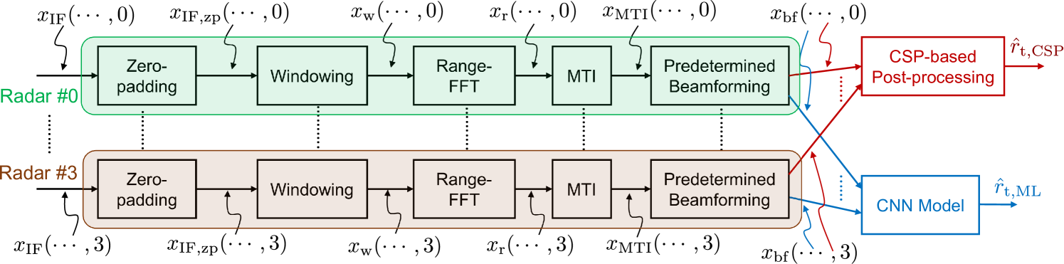
Figure 3: Flowchart of the radar signal processing pipeline implemented on each radar sensor. II-C Radar Signal Pre-Processing
The signal processing pipeline for generating the feature is shown in Fig. 3. Let and denote the frame index, IF sample index, range bin, chirp index, RX antenna index, and the sensor index respectively. Each radar sensor transmits the FMCW waveform with parameters shown in Table I. For each frame , the received waveform is then down-converted to get the intermediate frequency (IF) signal , that corresponds to the radar return. From this, the range information corresponding to all scattering objects in the radar’s field of view (FoV) is obtained by computing the beamformed ‘range-FFT’ using the following sequence of steps.
(1) (2) (3) for . Here, zero-padding is performed in (1) to shrink the effective range-bin width to 11Note that while this shrinks the range bin width, the range resolution (i.e. minimum radial distance between two targets such that they appear as two distinct targets) is unchanged. Oversampling in the range domain minimizes the contribution of range quantization error in the system., where is the oversampling factor. The zero-padded signal is then used to compute the range-FFT in (3) after a windowing operation . The purpose of the latter is to trade-off the range-FFT sidelobe level with the mainlobe width. It is worthwhile to note that the IF signal contains only the in-phase component and hence, is a real-valued signal. Thus, the range-FFT is symmetric about . Clutter removal is then used to eliminate the scattered returns from static objects using an IIR moving target indication (MTI) filter to get the post-MTI range-FFT signal , given by
(4) where is the IIR filter response parameter and is the clutter estimate for the frame. Finally, to keep the feature dimension manageable for real-time implementation, averaging across chirps and boresight beamforming are performed to get the beamformed range-FFT feature using22Since the feature is obtained through linear operations on the raw IF signal, averaging across chirps and boresight beamforming can equivalently be performed on the IF signal prior to range-fft as well.
(5) Note that for uniform linear/planar arrays, boresight beamforming is equivalent to signal averaging across RX antennas.
II-D Ground Truth
For each touch event, the capacitive touchscreen-based ground truth (GT) information is composed of the relative location and touch timestamp (), such that and . The relative locations are converted to locations in the radar coordinate system using knowledge of the reference radar location w.r.t. the touch area. We use the sign convention shown in Fig 1(b), using which the GT coordinates are calculated using
(6) 
Figure 4: The four-channel input ( consists of heatmaps from the four mmWave radars. The Deep Convolutional Neural Network consisting of three Convolution2D layers and Maxpooling2D and one Dense layer. The final dense layer outputs the 2D position estimate () of the touch event on the display. III Conventional Signal Processing (CSP)-based Positioning
To improve the accuracy of the conventional signal processing-based estimates, we use range estimates from the beamformed signal, as well as the per-RX signals. Firstly, the post-MTI range-FFT from each RX antenna is averaged across chirps using
(7) Then, range estimates corresponding to the per-RX () as well as beamformed signals () are estimated using
(8) (9) To have reliable ranging performance in the presence of low SNR conditions and strong clutter regions (e.g. portion of the hand excluding the finger such as shoulder, torso, palm etc.), we invalidate the range estimate when there is no consensus among the different per-RX range estimates. The range estimate from the sensor is computed using
(10) where is the range consensus tolerance, and is the range offset for the sensor, which is obtained using a one-time calibration of the localization environment. Let be the radar frame index corresponding to the touch event. Then, the range estimates are averaged over a window of frames, to mitigate the unavailability of range estimates, resulting in a range estimate , where .
Finally, the target’s position estimate () is obtained by solving the nonlinear least squares (NLS) problem [11]
(11) 
Figure 5: Partitioning of touch points into train/validation/test datasets, and their locations relative to the radar sensors. In our testbed, the radar locations are cm, cm, cm, and cm. IV Deep Neural Network-based Positioning
IV-A Feature Generation
The datastream from each radar sensor and the capacitive touchscreen are collected independently without explicit synchronization. The relatively high sampling rate of the radar ( Hz) and the touchscreen ( Hz) w.r.t. the finger movement speed eliminates the need for explicit sensor synchronization. The radar frame indices corresponding to each touch event are found using the GT touch time . Suppose the radar frame index corresponding to the touch event is For each touch event, the feature contains the beamformed range-FFT for all radar sensors for the frames for the range bin indices , where is the maximum possible target distance on the display. In our setup, . The feature for the touch event is the tensor , comprising of four heatmaps, each corresponding to one of the radar sensors.
IV-B Machine Learning Model Architecture
The proposed CNN-based architecture used in this work is shown in Fig. 4, which is similar to the LeNet-5 architecture [12] except it uses 3 layers of convolution with 3 max-pooling layers rather than 3 layers of convolution with 2 average pooling in the original architecture. We use three cascaded 2D-Convolutional + 2D-Maxpooling layers with filter sizes of and respectively, each with a kernel size of with ReLu activation. The maxpooling layer after convolution is used not only to reduce the feature size but also reduce over-fitting. This improves the generalization and also reduces the memory requirements to host the model on the device. After the convolution and pooling operations, the output is flattened, followed by a dense layer with units and then the final dense unit to generate the 2D position coordinates .
V Experimental Results
V-A Data Collection
The effective touch area on the 15.6 inch display is a rectangular area of length cm and width cm. In a single session, the data is collected across a point grid with an arbitrary offset from Radar 0 (), such that consecutive touch points are separated by cm along both the axes, as shown in Fig. 2. Data is collected in two stages:
-
1.
Training Dataset: In this stage, we collected data for 50 sessions. In each session, the robot touched the screen across a grid. After accumulating data across all sessions, the training data has the dimension .
-
2.
Validation and Test Datasets: In this stage, we collected data for 15 sessions. In each session, the robot touched the screen across a grid. The grid pattern was designed such that the validation/test touchpoints have a position offset of relative to the training touchpoints. This offset is introduced to test the generalization performance of the machine learning model to unseen data. Finally, touchpoints in the odd/even rows are allocated to the validation/test datasets, as shown in Fig. 5. Hence, the validation and dataset dimensions are and respectively.
V-B Range Calibration
For the conventional signal processing approach, the range calibration offset for each radar sensor () is estimated using the training dataset. For the touchpoint in the training set, the range estimate corresponding to each radar sensor is computed using (10), and is compared to the GT distance . Suppose the corresponding range error is . Then, the range calibration offset is estimated by computing the empirical average of the range errors for each sensor, i.e. , where . Note that this is the least-squares (LS) solution of the range-bias estimation problem under the model for , where is the range bias.

Figure 6: Distribution of position error for the Conventional Signal Processing and ML-based approaches. TABLE II: Position Error Performance Comparison on the Test Dataset Performance Metric CNN-based CSP-based Median Pointwise RMSE cm cm ile Pointwise RMSE cm cm Median Error (all points) cm cm ile Error (all points) cm cm 
(a) 
(b) Figure 7: Comparison of the root mean square (RMSE) position error heatmap (colorbar unit is cm) when using (a) conventional signal processing (after range calibration), and (b) our proposed CNN Model (from Fig. 4). V-C Position Error Performance Comparison
Fig. 6 shows the marginal distribution of position error (marginalized across the entire test dataset) for (a) training/validation/test datasets (CNN-based approach), and (b) the test dataset (CSP-based approach). First, we observe that there is more than a improvement in the validation/test position error performance in the median and percentile value, when using our CNN-based approach. Furthermore, we observe that these values are well within the range resolution of the radar waveform ( cm). On the other hand, we observe that while range calibration significantly improves the position error performance, the range-calibrated CSP-based approach achieves a percentile position error of cm, which is higher than . In alignment with our understanding of the physical limitations imposed by the radar waveform, the CSP-based method is unable to achieve sub-resolution accuracy. The key performance statistics are summarized in Table II.
Fig. 7 shows the heatmaps of RMSE position error for the CNN and CSP-based methods, for different touch regions on the display. These heatmaps are computed for the test dataset, visualized in Fig. 5. We observe that the CNN-based approach results in more than a improvement in the worst-case (maximum) RMSE, compared to that of the CSP-based approach. In general, there is more than a improvement in RMSE position error for the CNN-based approach relative to that of CSP, when comparing the point-wise median and percentile RMSE, as shown in Table II.

Figure 8: Distribution of the CNN inference time (, shown in blue) versus the half radar frame repetition interval (, shown in red). V-D Feasibility of Real-Time Implementation
Inference execution time and model size are two important aspects of the CNN model that determine whether it is suitable for real-time implementation. Our model has parameters, with a total size of KB. Thus, the memory required to store the model is quite small, and can be fitted on any standard system-on-chip (SoC).
For integrating any ML-based algorithm into a real-time localization system, it is important that the inference time () be smaller than the radar frame repetition interval (). To evaluate feasibility, we used a computer with an Intel i7-1185G7 processor, GB RAM, and no GPU. Fig. 8 shows the distribution of characterized on the test dataset. We observe that the median as well as the percentile inference time is ms, which is considerably smaller than the radar frame interval ( ms, in our system). Thus, the small model size and inference time indicates that our proposed CNN-based approach is well-suited for real-time implementation on general purpose processor-based platforms.
VI Conclusion
In this paper, we proposed a mmWave FMCW radar-based touch localization system, wherein a deep neural network was trained to accurately localize a robot-mounted metal finger. We demonstrated that the CNN-based approach achieved sub-resolution position error, and significantly outperformed conventional signal processing-based algorithms. Finally, we discussed the feasibility of implementing our proposed approach in real-time. The small (a) CNN model size, and (b) inference time on general purpose computing platforms (relative to the radar frame interval), point towards a very strong feasibility for implementation on a real-time localization system.
In this work, we have focused on accurate localization of robot-mounted targets. In general, extending this work to design localization systems for small targets such as accurate touch localization of human finger, and enabling handwriting on non touchscreen displays are worthwhile to enable low-cost technologies for human-screen interaction.
References
[1] C.-L. Lin, C.-S. Li, Y.-M. Chang, T.-C. Lin, J.-F. Chen, and U.-C. Lin, “Pressure Sensitive Stylus and Algorithm for Touchscreen Panel,” Journal of Display Technology, vol. 9, no. 1, pp. 17–23, 2013.-
1.
- [2] S. Yun, Y.-C. Chen, H. Zheng, L. Qiu, and W. Mao, “Strata: Fine-Grained Acoustic-based Device-Free Tracking,” in Proceedings of the 15th annual international conference on mobile systems, applications, and services, 2017, pp. 15–28.
- [3] D. Wu, R. Gao, Y. Zeng, J. Liu, L. Wang, T. Gu, and D. Zhang, “FingerDraw: Sub-Wavelength Level Finger Motion Tracking with WiFi Signals,” Proceedings of the ACM on Interactive, Mobile, Wearable and Ubiquitous Technologies, vol. 4, no. 1, pp. 1–27, 2020.
- [4] J. Wang, D. Vasisht, and D. Katabi, “RF-IDraw: Virtual Touch Screen in the Air using RF Signals,” ACM SIGCOMM Computer Communication Review, vol. 44, no. 4, pp. 235–246, 2014.
- [5] L. Shangguan and K. Jamieson, “Leveraging Electromagnetic Polarization in a Two-Antenna Whiteboard in the Air,” in Proceedings of the 12th International on Conference on emerging Networking EXperiments and Technologies, 2016, pp. 443–456.
- [6] T. Wei and X. Zhang, “mTrack: High-Precision Passive Tracking using Millimeter Wave Radios,” in Proceedings of the 21st Annual International Conference on Mobile Computing and Networking, 2015, pp. 117–129.
- [7] N. Xiao, P. Yang, X.-Y. Li, Y. Zhang, Y. Yan, and H. Zhou, “MilliBack: Real-Time Plug-n-Play Millimeter Level Tracking using Wireless Backscattering,” Proceedings of the ACM on Interactive, Mobile, Wearable and Ubiquitous Technologies, vol. 3, no. 3, pp. 1–23, 2019.
- [8] Y. Cao, A. Dhekne, and M. Ammar, “ITrackU: Tracking a Pen-like Instrument via UWB-IMU Fusion,” in Proceedings of the 19th Annual International Conference on Mobile Systems, Applications, and Services, 2021, pp. 453–466.
- [9] N. Hendy, H. M. Fayek, and A. Al-Hourani, “Deep Learning Approaches for Air-Writing Using Single UWB Radar,” IEEE Sensors Journal, vol. 22, no. 12, pp. 11 989–12 001, 2022.
- [10] F. Khan, S. K. Leem, and S. H. Cho, “In-Air Continuous Writing Using UWB Impulse Radar Sensors,” IEEE Access, vol. 8, pp. 99 302–99 311, 2020.
- [11] R. Zekavat and R. M. Buehrer, Handbook of Position Location: Theory, Practice and Advances. Wiley-IEEE Press, 2019.
- [12] Y. Lecun, L. Bottou, Y. Bengio, and P. Haffner, “Gradient-based Learning Applied to Document Recognition,” Proceedings of the IEEE, vol. 86, no. 11, pp. 2278–2324, 1998.
- [13] Z. Shen, S. Li, X. Zhao, and J. Zou, “CT-Auth: Capacitive Touchscreen-Based Continuous Authentication on Smartphones,” IEEE Transactions on Knowledge and Data Engineering, pp. 1–16, 2023.
- [14] J. Yan, C. C. J. M. Tiberius, G. J. M. Janssen, P. J. G. Teunissen, and G. Bellusci, “Review of Range-based Positioning Algorithms,” IEEE Aerospace and Electronic Systems Magazine, vol. 28, no. 8, pp. 2–27, 2013.
- [15] R. M. Rao, A. V. Padaki, B. L. Ng, Y. Yang, M.-S. Kang, and V. Marojevic, “ToA-Based Localization of Far-Away Targets: Equi-DOP Surfaces, Asymptotic Bounds, and Dimension Adaptation,” IEEE Transactions on Vehicular Technology, vol. 70, no. 10, pp. 11 089–11 094, 2021.
- [16] R. M. Rao and D.-R. Emenonye, “Iterative RNDOP-Optimal Anchor Placement for Beyond Convex Hull ToA-Based Localization: Performance Bounds and Heuristic Algorithms,” IEEE Transactions on Vehicular Technology, vol. 73, no. 5, pp. 7287–7303, 2024.
- [17] L. Badriasl and K. Dogancay, “Three-Dimensional Target Motion Analysis using Azimuth/Elevation Angles,” IEEE Transactions on Aerospace and Electronic Systems, vol. 50, no. 4, pp. 3178–3194, 2014.
- [18] A. Santra and S. Hazra, Deep Learning Applications of Short-Range Radars. Artech House, 2020.
- [19] F. Uysal, “Phase-Coded FMCW Automotive Radar: System Design and Interference Mitigation,” IEEE Transactions on Vehicular Technology, vol. 69, no. 1, pp. 270–281, 2020.
-
[20]


No comments:
Post a Comment