Tuesday, February 20, 2024

High Frame-Rate Imaging Using Swarm of UAV-Borne Radars | IEEE Journals & Magazine | IEEE Xplore

Fig. 3. - Illustration of high frame-rate imaging using collaborative radar swarm of UAVs, where radar operates at traditional microwave frequency band, for example, K-band.


High Frame-Rate Imaging Using Swarm of UAV-Borne Radars | IEEE Journals & Magazine | IEEE Xplore

Abstract: High frame-rate imaging of synthetic aperture radar (SAR), known as video SAR, has received much research interest these years. It usually operates at extremely high frequency and even THz band as a technical tradeoff between high frame rate and high resolution. As a result, video SAR system always suffers from limited functional range due to strong atmospheric attenuation of signals. 

This article attempts to present a new high frame-rate collaborative imaging regime in the microwave frequency band based on a swarm of unmanned aerial vehicles (UAVs). The spatial degrees of freedom are employed to shorten the synthetic time and thus improve the frame rate. More specifically, the long synthetic aperture is split into multiple short subapertures, and each UAV-borne radar implements short subaperture imaging in a short time. 

Then, the accelerated fast back-projection (AFBP) algorithm is employed to fuse multiple subimages to produce an image with high azimuth resolution. To implement the collaborative working of swarm of UAV-borne radars, a suitable orthogonal waveform is selected and a useful spatial configuration of the swarm is designed to compensate for the effect of the orthogonal waveform on imaging. Simulation results have been presented to highlight the advantages of collaborative imaging using a swarm of UAV-borne radars.

J. Ding, K. Zhang, X. Huang and Z. Xu, "High Frame-Rate Imaging Using Swarm of UAV-Borne Radars," in IEEE Transactions on Geoscience and Remote Sensing, vol. 62, pp. 1-12, 2024, Art no. 5204912, doi: 10.1109/TGRS.2024.3362630.


keywords: {Radar imaging; Radar;Imaging; Synthetic aperture radar; Apertures; Collaboration; Image resolution; Collaborative radar imaging; microwave high frame-rate imaging; radar network; synthetic aperture radar (SAR); video SAR},


URL: https://ieeexplore.ieee.org/stamp/stamp.jsp?tp=&arnumber=10428066&isnumber=10354519


Published in: IEEE Transactions on Geoscience and Remote Sensing ( Volume: 62)

Article Sequence Number: 5204912
Date of Publication: 08 February 2024
ISSN Information:
Publisher: IEEE
Funding Agency:
 

SECTION I. Introduction

Radar mounted on a civil unmanned aerial vehicle (UAV) has recently entered a period of significant progress in technology innovations, as researchers continue to explore their applications, and particularly, UAV-based radar imaging has been extensively researched [1], [2]. Most recently, the use of UAV swarms is highly expected to open a gate of various new applications of radar because of high flexibility and low cost. In the past years, some successful experiments of UAV swarms have been demonstrated worldwide with an emphasis on coordinated formation flight [3], [4], [5], which inspires researchers to pay much attention to the swarm of UAV-borne radars. Unfortunately, the implementation of collaborative working of the swarm of UAV-borne radars is greatly hampered due to a few technical difficulties, such as reliable solution of system precise synchronization and dynamic communication, which differs a lot from the payloads of photoelectric sensors that have been widely mounted on UAVs. The analysis and development of the swarm of UAV-borne radars are relatively underexplored until now.

It has long been recognized that distributed collaborative radar networks with a higher degree of coordination than conventional multistatic radars could provide an entirely new paradigm to overcome fundamental limitations of today’s radars that work independently or with poor collaboration [6], [7]. However, the previous efforts in collaborative radar network are mostly restricted to ground-based radar systems with limited dynamics, technically because they strongly rely on optical fibers to ensure high-quality and high coherence of signals. This implementation becomes very difficult, if not impossible, in airborne scenarios due to the high dynamics of platforms. This article attempts to present a useful collaborative imaging regime based on a radar swarm of UAVs that can be afforded by state-of-the-art technologies.

It has been highly desired in the radar community to develop a microwave sensor with high resolution that operates as effectively as current electro-optical sensors. Video synthetic aperture radar (SAR), an area of great current activity, can provide a persistent view of the scene of interest by high frame-rate imaging [8], [9], [10]. Additionally, a moving target often leaves dynamic shadows at their true instant position in sequential images, which allows for an alternative solution for detection, location, and tracking of moving targets [11], [12]. The imaging frame rate determines what kind of target we can track. There is always a trade-off between resolution and frame rate, which pushes the operational frequency of the radar to enter the THz band [13], [14]. However, the use of such a high frequency significantly adds to atmospheric attenuation of radar signals, and therefore, the growing concern regarding video SAR is the limited functional range, which in many cases is not acceptable. It is highly expected that video SAR systems can work in classical radar bands, for example, K-band.

When video SAR operates at a relatively low frequency, there are still two approaches to achieving a high frame rate. The first is to increase the speed of the radar platform [15]. As the speed of the platform increases, the coherent processing time to obtain the desired azimuth resolution decreases, and thus, the frame rate increases. As a side effect, the azimuth Doppler bandwidth expands, which often results in the Doppler ambiguity of the SAR system. Moreover, the platform speed is not adjustable in many applications. The second approach is to improve the aperture overlapping ratio in image formation, which has been often used for obtaining a high frame rate. However, the negative result is no-return area in the SAR scene may quickly be washed out since the synthetic time of each frame is not reduced in aperture overlapping processing, which adds to the difficulty of the detection of moving target shadow.

Distributed airborne radar utilizes multiplatform to create larger synthetic aperture and can obtain high imaging resolution [16]. In other words, high-resolution images are available in a shorter synthetic duration by fusing multiview information from distributed radars. Actually, the swarm of UAV-borne radars has much higher flexibility in configuration designation than the common airborne counterparts [21], which gives rise to high frame-rate imaging without relying on aperture overlapping in classical radar bands.

This article attempts to demonstrate a collaborative radar imaging approach using the swarm of UAV-borne radars, which is an alternative for high frame-rate imaging in classical radar frequency bands rather than video SAR designed in THz frequency. The proposed approach has been verified by using simulations. The article is organized as follows. Section II briefly describes video SAR and the accelerated fast back-projection (AFBP) algorithm. Section III presents the developed framework for high frame-rate imaging based on the swarm of UAV-borne radars. The experimental examination are detailed in Section IV, and Section V concludes this article.

SECTION II. Preliminaries

A. Video SAR

Video SAR is a classical high frame-rate imaging system, which can generate sequential SAR images at a frame rate similar to conventional video formats, and the frame rate can be given as

fps=1(1−γ)Ta=v(1−γ)L=2ρafcv(1−γ)cR(1)
View SourceRight-click on figure for MathML and additional features. where Ta is the synthetic aperture time, L is the length of synthetic aperture, ρa is the azimuth resolution, fc is center frequency, v is the velocity of the radar platform, c is the speed of light, R is the range from the radar to the scene center, and γ is the data overlap rate.

In conventional SAR imagery, moving targets are detected through their Doppler energy. However, the Doppler may be shifted or smeared. In contrast, moving target shadows precisely present their locations and motion [23]. Consequently, we can find moving targets by detecting their dynamic shadows in video SAR image sequences [11], [12]. The performance of moving target detection by shadow is associated with the difference between the shadow and its surrounding background. The shadow-to-background ratio (SBHR) statistically describes the intensity contrast between a moving target shadow and its surrounding background [12]. The smaller the SHBR, the darker the shadow, and the easier to detect. For a moving target with the length of Lm and the velocity of vt , the SBHR of a ground point at the shadow center can be expressed as

SHBRTc=σn+(1−Tc/Ta)σbσn+σb=min(Ta,Lm/vt)(2)
View SourceRight-click on figure for MathML and additional features.where σn and σb represents the equivalent backscatter coefficient of noise and background, respectively. Tc is the occlusion time of the ground point at the shadow center. Obviously, the SBHR is associated with the synthetic time Ta rather than the data overlap rate γ . In other words, improving the frame rate by overlapped processing does not shorten the synthetic time, which cannot benefit the detection and tracking of moving target shadows. Hence, this work aims at high frame-rate imaging without overlapped SAR processing.

B. Accelerated Fast Back-Projection Algorithm

The AFBP algorithm [27] has been developed for spotlight SAR imaging. Thanks to the unified pseudo-polar coordinate system used in subimage formation, the AFBP can efficiently implement image fusion via fast Fourier transform (FFT) and circular shift, which avoids 2-D image-domain interpolation in the classical fast back-projection (FBP) algorithm [26]. The subaperture division and the imaging coordinate system are illustrated in Fig. 1, where the platform moves along a straight flight path, generating a synthetic aperture of length L . The trajectory is defined as the x -axis with the origin O at the center of the synthetic aperture. The full synthetic aperture is divided into I subapertures with an equal length of l=L/I . The imaging coordinate (ρ,α) is constructed at the full aperture center, where ρ denotes the distance from origin O to the point, and α denotes the sine of the angle between the y -axis and the radar line of sight.

Fig. 1. - Aperture division and pseudo-polar grids used in the AFBP algorithm.
Fig. 1. Aperture division and pseudo-polar grids used in the AFBP algorithm.

The wavenumber spectrum of the i th subimage can be given by

Ii(kρ,kα)=rect[kρ−kρcΔkρ]exp(−jkρρ)×rect[kα−kαiΔkαi]exp(−jkαα)(3)
View SourceRight-click on figure for MathML and additional features. and the angular wavenumber variables are defined as
⎧⎩⎨⎪⎪kα=kρxkαi=kρxiΔkαi=kρl(4)
View SourceRight-click on figure for MathML and additional features.where kρ is the radial wavenumber, kρc is the center of radial wavenumber, Δkρ is the extent of range wavenumber, kα is the angular wavenumber, kαi is the center of the i th angular wavenumber, xi is the center of the i th subaperture, and Δkαi is the extent of angular wavenumber.

Equations (3) and (4) reveal the linear relation between angular wavenumber kα and aperture position x . Since the aperture positions are continuous, the spectra of the subimages can be connected without gaps. However, due to the coarse angular interval, there may be ambiguity in the wavenumber spectrum, which should be eliminated before the spectrum connection. Fig. 2 presents the spectrum fusion process.

Fig. 2. - Wavenumber spectrum fusion.
Fig. 2. Wavenumber spectrum fusion.

The AFBP procedure can be outlined as follows: 1) forming multiple subimages with coarse angular resolution in the unified pseudo-polar coordinate system; 2) transforming the subimages into the wavenumber domain by FFT; 3) performing spectrum center correction and spectrum connection; and 4) transforming the complete wavenumber spectrum back to image domain to obtain a full-resolution SAR image.

SECTION III. Collaborative High Frame-Rate Imaging

For the traditional SAR system with high azimuth resolution, increasing the center frequency to the W-band [17] or even THz band [13] can significantly reduce the synthetic aperture time, thereby improving frame rate and making moving target shadows easier observation. However, the signal with extremely high frequency suffers from atmospheric attenuation while the radar platform speed is limited by some physical factors. In contrast, the swarm of UAV-borne radars is completely dispersed in space, which makes it possible to shorten the synthetic time. The swarm of UAV-borne radars can be configured flexibly, which enables the multiview observation of the region of interest. Then, by fusing multiview information of multiple UAV-borne radars, high azimuth resolution can be achieved.

When each UAV-borne radar works in a self-transmitting and self-receiving mode, the collaborative imaging system based on a radar swarm of UAVs can be regarded as the collection of multiple independent UAV-borne SARs. In this case, as illustrated in Fig. 3, the long synthetic aperture to obtain high azimuth resolution can be split into multiple short subapertures, and each UAV-borne SAR implements short subaperture imaging to generate a low-resolution image. Finally, multiple low-resolution images are fused to generate an image with the desired high azimuth resolution. As a result, the synthetic aperture time is proportional to the inverse of the number of UAVs. From (9), the frame rate of the imaging system based on the swarm of UAV-borne radars can be expressed as

fps=vN(1−γ)L=2ρafcvN(1−γ)cR(5)
View SourceRight-click on figure for MathML and additional features. where N is the number of UAVs. Obviously, increasing the number of UAV platforms can linearly increase the imaging frame rate.

Fig. 3. - Illustration of high frame-rate imaging using collaborative radar swarm of UAVs, where radar operates at traditional microwave frequency band, for example, K-band.
Fig. 3. Illustration of high frame-rate imaging using collaborative radar swarm of UAVs, where radar operates at traditional microwave frequency band, for example, K-band.

As opposed to video SAR, collaborative imaging based on the swarm of UAVs can reduce the synthetic aperture time Ta to the time Ta/N . Hence, from (2), in the imagery obtained by the collaborative imaging, the SBHR of a ground point at the shadow center is

SHBRTc=σn+(1−TcN/Ta)σbσn+σb=min(Ta/N,Lm/vt).(6)
View SourceRight-click on figure for MathML and additional features.

We compare the SBHR at the shadow center in SAR images obtained by the two imaging modes. As shown in Table I, compared to video SAR, collaborative imaging can reduce the SBHR when the moving target speed is greater than Lm/Ta . Furthermore, for a moving target with a size of 2×5 m, SHBR curves of its shadow varying with target velocity and number of UAVs are shown in Fig. 4, where the red dotted line represents the detection requirement of SHBR (−1.5 dB) and the equivalent backscatter coefficients of noise and background are set as −34.5 and −16.5 dB, respectively. It should be pointed out that collaborative imaging degenerates to video SAR imaging when the number of UAVs is 1. Obviously, the greater the number of UAVs, the lower the SHBR of the moving target shadow, and the higher the maximum detectable velocity. It can be concluded that collaborative imaging has the potential for more accurate detection of moving targets with shadows aided.

TABLE I SBHR at the Shadow Center in SAR Images From the Two Imaging Modes
Table I- 
SBHR at the Shadow Center in SAR Images From the Two Imaging Modes
Fig. 4. - SHBR curves of moving target shadow varying with target velocity and number of UAVs, where the red dotted line represents the detection requirement of SHBR (−1.5 dB).
Fig. 4.

SHBR curves of moving target shadow varying with target velocity and number of UAVs, where the red dotted line represents the detection requirement of SHBR (−1.5 dB).

A. Operating Mode and Waveform Design

The basis of collaborative imaging based on the swarm of UAV-borne radars is to transmit multiple orthogonal waveforms simultaneously, and each waveform is associated with each UAV-borne radar. Since the frequency-modulated continuous waveform (FMCW) is always used in UAV-borne radars for the sake of miniaturization and lightweight, the waveform suitable for the FMCW radar should be selected from various orthogonal waveforms [18], [19], [20]. In FMCW radar systems, dechirping processing is employed to alleviate sampling requirements, where a beat signal whose bandwidth is narrower than the transmission bandwidth is generated from the backscattered signal. Making full use of the advantage of the dechirping processing, an orthogonal waveform named beat frequency division (BFD) is proposed [20]. Although the proposed waveform is not orthogonal during transmission, high orthogonality can be obtained after the dechirping processing. More specifically, when adopting the BFD waveform, as shown in Fig. 5, each UAV-borne radar transmits signals at the same chirp rate γ but with a small frequency offset Δfb . Obviously, most of the transmission frequencies between UAV-borne radars overlap due to the small frequency offset Δfb , which makes the subsequent image coherent fusion possible. After the dechirping processing, the superposition reflected signals from multiple UAV-borne radar are separated when the frequency offset Δfb satisfies

Δfb>2Rswathγc(7)
View SourceRight-click on figure for MathML and additional features. where Rswath is the range swath of the observation scene. Finally, we can get the desired signal by filtering.

Fig. 5. - Time-frequency diagrams of radar signals. (a) Transmit signal. (b) Receive signal. (c) Beat signal. (d) Filtered signal.
Fig. 5. Time-frequency diagrams of radar signals. (a) Transmit signal. (b) Receive signal. (c) Beat signal. (d) Filtered signal.

Due to the spatial distribution of multiple UAV platforms, time-frequency synchronization errors and phase synchronization errors are inevitable in the swarm of UAV-borne radars. To reduce the effect of synchronization errors, it is crucial to choose the operating mode for the swarm of UAV-borne radars. Common distributed radar systems either operate in a one-transmitter-multiple-receiver mode or in a multiple-transmitter-multiple-receiver mode, where the transmitting and receiving oscillators are generally separated. Consequently, both the two modes require the precise calibration of synchronization errors caused by different radar local oscillators among distributed UAVs, which is extremely difficult. To alleviate the effect of synchronization errors, the swarm of UAV-borne radars in this article operates in a self-transmitting and self-receiving mode, where the transmitting and receiving ends share the same reference signal source. Consequently, the frequency and phase synchronization errors can be canceled as in a monostatic SAR, enabling coherent processing across multiple platforms. In addition, time-frequency synchronization errors have an effect on the orthogonality when the BFD waveform is adopted for collaborative imaging. More details are described by the following mathematical formulas.

When the BFD waveform is adopted, the signal transmitted from the n th UAV-borne radar can be expressed as

Snt(t,tr)=rect(trTd)exp[j2π(fc+(n−1)Δfb)t+jπγt2r](8)
View SourceRight-click on figure for MathML and additional features. where tr is the fast time, Td is sweep duration, and γ is the chirp rate.

Since the swarm of UAV-borne radars is spatially distributed, there are time-frequency synchronization errors and phase synchronization errors between different UAV-borne radars, and thus the signal transmitted from the m th UAV-borne radar can be expressed as

Smt(t,tr)=rect(tr+δtnmTd)×exp[j2π(fc+δfnm)(t+δtnm)]×exp[j2π(m−1)Δfb(t+δtnm)]×exp[jπγ(tr+δtnm)2+jβnm](9)
View SourceRight-click on figure for MathML and additional features. where δtnm , δfnm and βnm represent time synchronization errors, frequency synchronization errors, and phase synchronization errors between the n th UAV-borne radar and the m th UAV-borne radar, respectively. When n=m , δtnm=0 , δfnm=0 and βnm=0 .

The reflected signal received by the n th UAV-borne radar is

Snr(t,tr)=∑m=1Nrect(tr+δtnm−Rnm(t)/cTd)×exp[jπγ(tr+δtnm−Rnm(t)c)2+jβnm]×exp[j2π(fc+δfnm)(t+δtnm−Rnm(t)c)]×exp[j2π(m−1)Δfb(t+δtnm−Rnm(t)c)](10)
View SourceRight-click on figure for MathML and additional features. where Rnm(t) is the sum of the distances from the n th UAV-borne radar and the m th UAV-borne radar to a ground point target.

In the dechirping processing, the reference signal is a replica of the transmitted waveform delayed by the time to the center of the scene, and the reference signal of the n th UAV-borne radar can be written as

Snref(t,tr)=rect(tr−2Rs/cTref)exp[jπγ(tr−2Rsc)2]×exp[j2π(fc+(n−1)Δfb)(t−2Rsc)](11)
View SourceRight-click on figure for MathML and additional features. where Tref is the sweep duration of the reference signal, and Rs is the distance between the UAV and the scene center.

After dechirping, the beat signal of the n th UAV-borne radar can be expressed as

Snb(t,tr)=∑m=1Nrect(tr+δtnm−Rnm(t)/cTd)rect(tr−2Rs/cTref)×exp[−j2πγ(tr+δtnm−2Rsc)(Rnm(t)c−2Rsc)]×exp[j2π((m−n)Δfb+γδtnm+δfnm)(t−Rnm(t)c)]×exp[−j2π(fc+(n−1)Δfb)(Rnm(t)c−2Rsc)]×exp[jπγ(Rnm(t)c−2Rsc)2]×exp[jπγδt2nm+jβnm].(12)
View SourceRight-click on figure for MathML and additional features.

Inspecting the second exponential term in (12), we can find that time synchronization errors and frequency synchronization errors have an effect on the signal separation. In this case, to ensure the interferences from other UAV-borne radars can be easily filtered, the frequency offset Δfb should satisfy

Δfb>2Rswathγc+2γ|δtmax|+2|δfmax|(13)
View SourceRight-click on figure for MathML and additional features. where δtmax and δfmax represent the maximum values of time synchronization errors and frequency synchronization errors between adjacent UAV-borne radars, respectively.

To remove the last exponential term in (12) that represents the synchronization errors, a low pass filter is employed to filter out the interferences from the other UAV-borne radar, and the signal from the n th UAV-borne radar itself becomes

Snf(t,tr)=rect(tr−2Rnn(t)/cTd)rect(tr−2Rs/cTref)×exp[−j2πγ(2Rnn(t)c−2Rsc)(tr−2Rsc)]×exp[−j2π(fc+(n−1)Δfb)(2Rnn(t)c−2Rsc)]×exp[jπγ(2Rnn(t)c−2Rsc)2].(14)
View SourceRight-click on figure for MathML and additional features.

After compensating for the residual video phase (RVP) [24], the filtered signal can be expressed as

Snf(t,tr)=rect(tr−2Rs/cTd)×exp[−j2πγ(tr−2Rsc)(2Rnn(t)c−2Rsc)]×exp[−j2π(fc+(n−1)Δfb)(2Rnn(t)c−2Rsc)].(15)
View SourceRight-click on figure for MathML and additional features.

For simplicity, the filtered signal can be rewritten as

Snf(t,Kr)=rect(Kr4πB/c)exp[−j(Kr+Knc)(Rnn(t)−Rs)](16)
View SourceRight-click on figure for MathML and additional features. where B is the bandwidth, Kr is the range wavenumber, and Knc=4π(fc+(n−1)Δfb)/c is the center wavenumber of the echo data from the n th UAV-borne radar.

Further, after compensating the reference range Rs , we have

Snf(t,Kr)=rect(Kr4πB/c)exp[−j(Kr+Knc)Rnn(t)].(17)
View SourceRight-click on figure for MathML and additional features.

B. Imaging Algorithm and Configuration Design

A simple spatial configuration of the swarm of UAVs for the collaborative imaging is shown in Fig. 6, where N UAV-borne radars move along a circular flight path with the radius of Rc at the same speed v . The beams of N UAV-borne radar are spotlighted on the same observed scene with the radius of Ra . The position of the first UAV-borne radar is (Rcsinθ,Rccosθ,H) , where θ∈[0,2π] is the aspect angle and H represents the height of the UAV. Meanwhile, the position of the n th UAV-borne radar is (Rcsin(θ+(n−1)Δθ),Rccos(θ+(n−1)Δθ),H) , where Δθ is the interval of the azimuth angle between adjacent UAV-borne radars and is defined as

Δθ=c2fc(N−1)ρa.(18)
View SourceRight-click on figure for MathML and additional features. In fact, Δθ is determined by the desired azimuth resolution ρa . After RcΔθ/v seconds of flight, the echo data of N UAV-borne radars can be fused to form a long aperture observation, and then through imaging processing, one image frame with high azimuth resolution can be obtained.

Fig. 6. - Geometric observation model.
Fig. 6. Geometric observation model.

However, the center wavenumber of the echo data from different UAV-borne radars is different due to the frequency offset. As a result, the frequency-domain imaging algorithms, such as chirp-scaling algorithm, polar format algorithm, cannot be applied directly to do the collaborative imaging. In addition, since the swarm of UAV-borne radars is spatially distributed, the multichannel reconstruction algorithm [25] is not suitable for the collaborative imaging. By contrast, the back-projection (BP) algorithm is capable of fusing the data from N UAV-borne radars directly by projecting the data onto the same imaging coordinate system.

To improve processing efficiency of the BP algorithm, the FBP algorithm [26] and the fast factorized BP (FFBP) algorithm [28] split the synthetic aperture to multiple short subapertures, and then fuse low-resolution images generated from subapertures by using 2-D interpolation. However, the interpolation inevitably brings errors and also limits the efficiency. In the Cartesian factorized BP (CFBP) algorithm [29], [30], two spectrum compressing filters are used to unfold the spectrums of low-resolution images generated from subapertures, and thus low-resolution images can be fused without interpolation to produce a high-resolution image. Unlike the CFBP projects data onto a Cartesian coordinate system, the AFBP reconstructs the image in a unified pseudo-polar coordinate system and efficiently achieves image fusion by wavenumber spectrum connection. Moreover, due to the inherent processing architecture, the AFBP can be implemented on distributed processors for further efficiency, which fits well with the spatial distribution nature of the swarm.

When the AFBP is applied to the collaborative imaging, the echo data of N UAV-borne radars are projected onto a unified ground pseudo-polar coordinate system. The coarse image generated from the echo data of n th UAV-borne radar can be expressed as

In(ρ,α)=∑t∑KrSnf(t,Kr)exp[j(Kr+Knc)R(ρ,α)](19)
View SourceRight-click on figure for MathML and additional features. where
ϕR(ρ,α)=(Rcsinϕ−ρα)2+(Rc(1−cosϕ)−ρ1−α2−−−−−√)2+H2−−−−−−−−−−−−−−−−−−−−−−−−−−−−−−−−−−−−−−−−√∈[(n−1)Δθ−NΔθ/2,nΔθ−NΔθ/2](20)
View SourceRight-click on figure for MathML and additional features. is the range from n th UAV-borne radar to the ground point located at (ρ,α,0) in the unified ground pseudo-polar coordinate system.

The Fourier transform of In(ρ,α) with respect to both ρ and α can be expressed as

I~n(Kρ,Kα)=∑ρ∑αIn(ρ,α)exp(−jKρρ−jKαα).(21)
View SourceRight-click on figure for MathML and additional features.

According to the principle of stationary phase, we have

∂∂ρ((Kr+Knc)R(ρ,α)−Kρρ)∂∂α((Kr+Knc)R(ρ,α)−Kαα)=0=0.(22)
View SourceRight-click on figure for MathML and additional features.Then, Kα and Kρ can be approximated as
KαKρ≈(Kr+Knc)Rc(R2c+H2)−−−−−−−−−√Rcsinϕ≈(Kr+Knc)Rc(R2c+H2)−−−−−−−−−√.(23)
View SourceRight-click on figure for MathML and additional features. Further, the center of Kα and Kρ can be written as
KcnαKcnρ=KncRc(R2c+H2)−−−−−−−−−√Rcsinϕ=KncRc(R2c+H2)−−−−−−−−−√.(24)
View SourceRight-click on figure for MathML and additional features.

Obviously, due to the frequency offset, the 2-D wavenumber spectra of the coarse images from different UAVs are not aligned along the radial wavenumber Kρ , which leads to the degradation of imaging performance. We thus design a useful configuration of the swarm of UAVs for the collaborative imaging. Specifically, N UAV-borne radars move along N circular flight paths with the same radius of Rc but at different heights. When the position of the first UAV-borne radar is (Rcsinθ,Rccosθ,H) , the position of the n th UAV-borne radar can be expressed as (Rcsin(θ+(n−1)Δθ),Rccos(θ+(n−1)Δθ),Hn) . Then, we make Kcnρ corresponding to different UAV-borne radars the same, which can be expressed as

Kcnρ=Kc1ρ.(25)
View SourceRight-click on figure for MathML and additional features.Namely,
KncRc(R2c+H2n)−−−−−−−−−√=K1cRc(R2c+H2)−−−−−−−−−√.(26)
View SourceRight-click on figure for MathML and additional features. The height of the n th UAV-borne radar Hn should satisfy
Hn=(fc+(n−1)Δffc)2(R2c+H2)−R2c−−−−−−−−−−−−−−−−−−−−−−−−−−−−−√.(27)
View SourceRight-click on figure for MathML and additional features.

The flowchart of the collaborative imaging based on the AFBP is illustrated in Fig. 7. First, in the unified ground pseudo-polar coordinate system, N subimages with low azimuth resolution are generated from the echo data of N UAV-borne radars individually by using the BP integral. Second, N subimages are transformed into the wavenumber domain by FFT. Due to the coarse angular interval in the subimages, their angular wavenumber spectra may be folding. The spectrum center correction is employed to unfold the spectra by circular shifting. More specifically, for the n th subimage, the center of its angular wavenumber spectrum should be shifted from zero to Kcnα . After the spectrum center correction, the spectrum connection is performed to directly connect wavenumber spectra of N subimages to obtain the complete wavenumber spectrum. Subsequently, we transform the complete wavenumber spectrum back to the image domain to obtain a high-resolution SAR image in the unified pseudo-polar coordinate system. Finally, the geometric correction is performed by projecting the high-resolution SAR image onto the Cartesian coordinate system via image-domain interpolation. Note that imaging efficiency is limited when the number of UAVs N is small. A simple but effective solution is to further divide the echo of each UAV-borne radar into M subapertures.

Fig. 7. - Flowchart of collaborative imaging of UAV swarm based on AFBP.
Fig. 7.

Flowchart of collaborative imaging of UAV swarm based on AFBP.

SECTION IV. Simulation Results

Simulation experiments have been used to assess the performance of the proposed collaborative high frame-rate imaging approach.

We compare the collaborative high frame-rate imaging system with the video SAR system in terms of imaging performance and the synthetic aperture time. The collaborative imaging system consists of six UAV-borne radars, and the beat frequency is 40 MHz. The parameters of the first UAV-borne radar are given in Table II. The heights of other UAVs can be calculated according to (27), and the imaging geometry is shown in Fig. 8. Nine stationary point targets with the same radar cross section are present, and their positions are listed in Table III. The parameters of a traditional video SAR system are the same as those of the first UAV-borne radar.

TABLE II Parameters of the Collaborative Imaging System
Table II- 
Parameters of the Collaborative Imaging System
TABLE III Position of Nine Point Targets
Table III- 
Position of Nine Point Targets
Fig. 8. - Collaborative imaging geometry of UAV swarm.
Fig. 8.

Collaborative imaging geometry of UAV swarm.

Fig. 9(a) and (b) shows the imaging result of the traditional video SAR system with the frame rate of 2.6 and 0.43 Hz, respectively. For the video SAR system operating in a common microwave band, high frame rate and high resolution are a contradiction. Fig. 9(c) is the result of the collaborative imaging system with a frame rate of 2.6 Hz. Obviously, compared to the traditional video SAR system, the collaborative imaging system achieves a higher frame rate at the same azimuth resolution, which indicates that the collaborative imaging system enables both high frame rate and high-resolution imaging in the common microwave band rather than the THz band.

Fig. 9. - Imaging results obtained by the two imaging modes. (a) and (b) Results of traditional video SAR system with the frame rate of 2.6 and 0.43 Hz, respectively. (c) Result of the collaborative imaging system with the frame rate of 2.6 Hz.
Fig. 9. Imaging results obtained by the two imaging modes. (a) and (b) Results of traditional video SAR system with the frame rate of 2.6 and 0.43 Hz, respectively. (c) Result of the collaborative imaging system with the frame rate of 2.6 Hz.

To verify the effectiveness of the adopted BFD waveform, the collaborative imaging result from the echo data without BFD demodulation is given in Fig. 10. When the BFD waveform is not adopted, the signals from six UAV-borne radars interfere with each other and thus the collaborative imaging result is not acceptable.

Fig. 10. - Collaborative imaging result without BFD demodulation.
Fig. 10. Collaborative imaging result without BFD demodulation.

Additionally, we compare and analyze the imaging performance of the collaborative imaging system under two spatial configurations. When six UAV-borne radars follow the same circular flight path, the imaging result in the pseudo-polar coordinate system is given in Fig. 11(a), and the corresponding wavenumber spectrum is shown in Fig. 11(c). Meanwhile, Fig. 11(b) displays the corresponding interpolation result in the Cartesian coordinate system for easier observation of resolution. It can be seen that the frequency offset leads to the misalignment of the wavenumber spectrum along the radial wavenumber Kρ , resulting in the distorted imaging result. In contrast, when six UAV-borne radars complete formation flight based on the designed spatial configuration, more satisfactory imaging result in the pseudo-polar and Cartesian coordinate systems can be obtained and are, respectively, shown in Fig. 11(d) and (e), and the corresponding wavenumber spectrum is given in Fig. 11(f). Obviously, the designed spatial configuration can compensate the effect of the frequency offset on the collaborative imaging.

Fig. 11. - Simulation results of the collaborative imaging system under two spatial configurations. (a) and (b) Imaging results in pseudo-polar and Cartesian coordinate systems, respectively, when all UAV-borne radars move along the same circular flight path. (d) and (e) Imaging results in pseudo-polar and Cartesian coordinate systems, respectively, when the collaborative imaging system works under the designed spatial configuration. (c) and (f) Corresponding wavenumber spectra of (a) and (d) under the two spatial configurations.
Fig. 11. Simulation results of the collaborative imaging system under two spatial configurations. 
a) and (b) Imaging results in pseudo-polar and Cartesian coordinate systems, respectively, when all UAV-borne radars move along the same circular flight path.
(d) and (e) Imaging results in pseudo-polar and Cartesian coordinate systems, respectively, when the collaborative imaging system works under the designed spatial configuration.
(c) and (f) Corresponding wavenumber spectra of (a) and (d) under the two spatial configurations.

However, it is very challenging in practice to control multiple UAVs to fly at ideal heights precisely, and thus height deviations are inevitable. We conduct a simulation to investigate the effect of height deviations on imaging performance. In the simulation, the actual heights of six UAVs are listed in Table IV, where the height deviations obey the Gaussian distribution with 1 variance and the mean of δh . Note that the probability of the up or down of deviation is the same. Fig. 12 shows the imaging results at different levels of height deviation. Fig. 12(a), (c), and (e) display the wavenumber spectra at different levels of height deviation. It can be seen that the misalignment of the wavenumber spectrum along the radial wavenumber becomes more severe with the increase of height deviation. Fig. 12(b), (d), and (f) shows the imaging results of point 9 at different levels of height deviation. Obviously, as the height deviation increases, the imaging results are more deformed and the sidelobes are more irregular, but the resolution is not significantly degraded.

TABLE IV Flight Heights of UAVs at Different Levels of Deviation
Table IV- 
Flight Heights of UAVs at Different Levels of Deviation
Fig. 12. - Imaging results at different levels of height deviation. (a), (c), and (e) Wavenumber spectra when height deviations obey the Gaussian distribution with the mean of 1, 5, and 10, respectively. (b), (d), and (f) Corresponding imaging results of a single point target.
Fig. 12. Imaging results at different levels of height deviation. (a), (c), and (e) Wavenumber spectra when height deviations obey the Gaussian distribution with the mean of 1, 5, and 10, respectively. (b), (d), and (f) Corresponding imaging results of a single point target.

The effect of the beat frequency offset is also a concern. The main simulation parameters are shown in Table II, and the beat frequency is reset to 30, 40, and 50 MHz, respectively. The imaging results of the collaborative imaging SAR system with different beat frequency offset are given in Fig. 13. The results have no noticeable change when the frequency offset increases thanks to the designed configuration.

Fig. 13. - Effect of the beat frequency offset on the collaborative imaging performance. (a)–(c) Result of the collaborative imaging with the beat frequency offset of 30, 40, and 50 MHz, respectively.
Fig. 13. Effect of the beat frequency offset on the collaborative imaging performance. (a)–(c) Result of the collaborative imaging with the beat frequency offset of 30, 40, and 50 MHz, respectively.

Furthermore, for the collaborative imaging system with the imaging frame rate of 2.6 Hz, the influence of the number of UAVs on the image performance is investigated. Fig. 14 shows the imaging results when the number of UAVs is, respectively, 2, 4, and 6. It can be seen that as the increase of the number of UAVs, the resolution is improved. Consequently, by increasing the number of UAVs, the collaborative imaging system can obtain SAR images with both high frame rate and high resolution.

Fig. 14. - Influence of the number of UAVs on collaborative imaging performance. (a)–(c) Imaging result with two, four, and six UAVs, respectively.
Fig. 14. Influence of the number of UAVs on collaborative imaging performance. (a)–(c) Imaging result with two, four, and six UAVs, respectively.

In addition, we investigate the influence of trajectory errors on imaging performance. Fig. 15(a) gives the imaging result under trajectory errors, where the energy is significantly defocusing along the azimuth direction. Fortunately, the AFBP algorithm establishes the Fourier transform relationship between the image domain and the wavenumber domain, and thus traditional auto-focusing algorithms can be employed to compensate for the effects of trajectory errors. By employing the phase gradient autofocus (PGA) [31] algorithm, we can obtain the focusing imaging result despite the presence of trajectory errors among multiple UAV platforms, as shown in Fig. 15(b). Therefore, the proposed approach in this article has the potential to mitigate the effect of trajectory errors.

Fig. 15. - Imaging results under the same trajectory error (a) before and (b) after autofocusing.
Fig. 15. Imaging results under the same trajectory error (a) before and (b) after autofocusing.

Finally, a collaborative imaging simulation is used to investigate the effect of the number of UAVs on the moving target shadows. The collaborative imaging results with the same resolution ρa=0.3 m but under different number of UAVs (1, 2, 4, and 6) are shown in Fig. 16. Four moving targets with different velocities (5, 10, 15, and 20 m/s) are arranged in a homogeneous scene. The equivalent backscatter coefficients of noise and background in the homogeneous scene is set to −34.5 and −16.5 dB, respectively. It should be pointed out that collaborative imaging degenerates to video SAR imaging when the number of UAV decreases to one. Compared to the traditional video SAR system, the collaborative imaging system relies on more platforms to create a large aperture in a shorter synthetic time, which results in a short target movement distance. Therefore, moving targets in the imagery obtained by the collaborative imaging system are more likely to produce distinct shadows, which is highly expected in shadow detection. Moreover, increasing the number of UAVs can make shadows more distinct and therefore improves the maximum detectable velocity significantly.

Fig. 16. - Simulation results of moving target shadow with different target velocities. (a)–(d) Result with one, two, four, and six UAVs, respectively.
Fig. 16. Simulation results of moving target shadow with different target velocities. (a)–(d) Result with one, two, four, and six UAVs, respectively.

SECTION V. Conclusion

Collaborative operation of airborne radar network has not received much research interest until recently. This article is the first, to the best of our knowledge, to discuss high-frame rate collaborative imaging in the research field related to the emerging technology of swarm of UAV-borne radars.

The collaborative imaging system consists of multiple self-transmitting and self-receiving UAV-borne radars. Each UAV-borne radar obtains short aperture data in a short time, and multiple aperture data are then fused to achieve the desired azimuth resolution by using the AFBP SAR algorithm. Moreover, the BFD waveform is introduced for collaborative operation of distributed UAV-borne radars, and we design a useful spatial configuration to suppress the effect of the BFD waveform on collaborative imaging. The simulation results have been presented to assess the performance of the proposed approach.


New Multi-Mode Radar Incorporates Video SAR | Unmanned Systems Technology
Caroline Rees

ga-asi-introduces-Eagle-Eye-radar

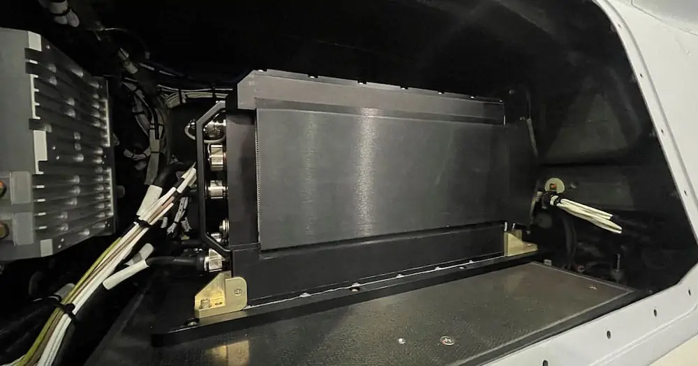
General Atomics Aeronautical Systems, Inc. (GA-ASI) has released the Eagle Eye radar, a new Multi-mode Radar (MMR) that has been installed and flown on a U.S. Army-operated Gray Eagle Extended Range (GE-ER) Unmanned Aerial Vehicle (UAV). 

Eagle Eye is a high-performance radar system that delivers high-resolution, photographic-quality imagery that can be captured through clouds, rain, dust, smoke and fog at multiple times the range of previous radars. It’s a drop-in solution for GE-ER and is designed to meet the range and accuracy to Detect, Identify, Locate & Report (DILR) stationary and moving targets relevant for Multi-Domain Operations (MDO) with Enhanced Range Cannon Artillery (ERCA). Eagle Eye radar can deliver precision air-to-surface targeting accuracy and superb wide-area search capabilities in support of Long-Range Precision Fires.

Featuring Synthetic Aperture Radar (SAR), Ground/Dismount Moving Target Indicator (GMTI/DMTI), and robust Maritime Wide Area Search (MWAS) modes, Eagle Eye’s search modes provide the wide-area coverage for any integrated sensor suite, allowing for cross-cue to a narrow Field-Of-View (FOV) Electro-Optical/Infrared (EO/IR) sensor.

The Eagle Eye’s first flight on the Army GE-ER aircraft took place in December 2021, incorporating the new Video SAR capability. Video SAR enables continuous collection and processing of radar data, allowing persistent observation of targets day or night and during inclement weather or atmospheric conditions. In addition, Eagle Eye’s processing techniques enable three modes – SAR Shadow Moving Detection, SAR Stationary Vehicle Detection and Moving Vehicle Detection as part of its Moving Target Indicator – to operate simultaneously.  

“The Video SAR in Eagle Eye provides all-weather tracking and revolutionizes precision targeting of both moving and stationary targets at the same time,” said GA-ASI Vice President of Army Programs Don Cattell. “This is a critical capability in an MDO environment to ensure military aviation, ground force and artillery have constant situational awareness and targeting of enemy combatants.”

GA-ASI Introduces New Eagle Eye Radar

GA-ASI Introduces New Eagle Eye Radar

New Radar Flies on U.S. Army Gray Eagle UAS; Features New Video SAR Capability

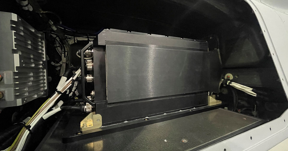
SAN DIEGO – 05 April 2022 – General Atomics Aeronautical Systems, Inc. (GA-ASI), a leader in Multi-mode Radar technology for Unmanned Aircraft Systems, introduces the Eagle Eye radar. The new MMR is installed and has flown on a U.S. Army-operated Gray Eagle Extended Range (GE-ER) UAS. Eagle Eye joins GA-ASI’s line of radar products, which includes the Lynx® MMR.

Eagle Eye is a high-performance radar system that delivers high-resolution, photographic-quality imagery that can be captured through clouds, rain, dust, smoke and fog at multiple times the range of previous radars. It’s a “drop-in solution” for Gray Eagle ER and is designed to meet the range and accuracy to Detect, Identify, Locate & Report (DILR) stationary and moving targets relevant for Multi-Domain Operations (MDO) with Enhanced Range Cannon Artillery (ERCA). Eagle Eye radar can deliver precision air-to-surface targeting accuracy and superb wide-area search capabilities in support of Long-Range Precision Fires.

Featuring Synthetic Aperture Radar (SAR), Ground/Dismount Moving Target Indicator (GMTI/DMTI), and robust Maritime Wide Area Search (MWAS) modes, Eagle Eye’s search modes provide the wide-area coverage for any integrated sensor suite, allowing for cross-cue to a narrow Field-of-View (FOV) Electro-optical/Infrared (EO/IR) sensor.

The Eagle Eye’s first flight on the Army GE-ER aircraft took place in December, incorporating the new Video SAR capability. Video SAR enables continuous collection and processing of radar data, allowing persistent observation of targets day or night and during inclement weather or atmospheric conditions. In addition, Eagle Eye’s processing techniques enables three modes – SAR Shadow Moving Detection, SAR Stationary Vehicle Detection and Moving Vehicle Detection as part of its Moving Target Indicator – to operate simultaneously.  

“The Video SAR in Eagle Eye provides all-weather tracking and revolutionizes precision targeting of both moving and stationary targets at the same time,” said GA-ASI Vice President of Army Programs Don Cattell. “This is a critical capability in an MDO environment to ensure military aviation, ground force and artillery have constant situational awareness and targeting of enemy combatants.”

About GA-ASI

General Atomics-Aeronautical Systems, Inc. (GA-ASI), an affiliate of General Atomics, is a leading designer and manufacturer of proven, reliable remotely piloted aircraft (RPA) systems, radars, and electro-optic and related mission systems, including the Predator® RPA series and the Lynx® Multi-mode Radar. With more than seven million flight hours, GA-ASI provides long-endurance, mission-capable aircraft with integrated sensor and data link systems required to deliver persistent flight that enables situational awareness and rapid strike. The company also produces a variety of ground control stations and sensor control/image analysis software, offers pilot training and support services, and develops meta-material antennas. For more information, visit www.ga-asi.com

Avenger, Lynx, Predator, SeaGuardian and SkyGuardian are registered trademarks of General Atomics Aeronautical Systems, Inc.

ga-asi Apr 5, 2022


Sunday, February 18, 2024

Russia - Would You Buy a used Carrier From these Guys - INS Vikramaditya: India Bought This Aircraft Carrier from Russia (Mistake?)


INS Vikramaditya 

"Vikramaditya" translates to "Brave in Valor" in Sanskrit and honors Emperor Vikramaditya, a legendary ruler known for his military prowess and cultural advancements. The name king Vikramaditya (Sanskrit: विक्रमादित्य) is a Sanskrit tatpurusha, from विक्रम (vikrama) meaning "valour" and आदित्य Āditya, son of Aditi.

Performance and Specifications:

Speed and Range:

  • Maximum speed: 30 knots (56 km/h)
  • Cruising speed: 18 knots (33 km/h)
  • Range: 7,000 nautical miles (13,000 km)

Airwing Size and Composition:

  • Maximum capacity: 32 aircraft (varies depending on specific mix)
  • Typical composition:
    • MiG-29K/KUB Fulcrum multirole fighters (16-18)
    • Kamov Ka-31 Helix AEW helicopters (4)
    • Sea King Mk.42C/D helicopters (4-6)
    • HAL Dhruv utility helicopters (2-4)

Cost

The exact cost of acquiring, modifying, and equipping the INS Vikramaditya is a complex issue with varying estimates and conflicting reports. Here's what we know:

Original Purchase:

  • India bought the decommissioned Soviet aircraft carrier Admiral Gorshkov from Russia in 2004 for $2.3 billion.

Refurbishment and Modernization:

  • Extensive refit and modernization work took place at the Sevmash shipyard in Russia between 2004 and 2013.
  • Initial estimates for the refit were around $2.9 billion, but the final cost likely exceeded that figure due to delays and additional modifications.

Additional Expenses:

  • Costs beyond direct purchase and refit include crew training, infrastructure upgrades, ammunition, aircraft acquisition, and ongoing maintenance.
  • Estimating these additional expenses is challenging due to their varied nature and potential fluctuations over time.

Overall Cost Estimates:

  • Various sources offer estimates for the total cost, ranging from $6.2 billion to $8 billion.
  • It's important to consider the limitations of these estimates, as they might not capture all potential expenditures or consider fluctuations in exchange rates over the project's timeline.

Challenges in Determining Exact Cost:

  • Limited transparency and potential confidentiality clauses in agreements with Russia can obscure precise figures.
  • Fluctuations in exchange rates and variable definitions of "cost" (acquisition, refit, ongoing expenses) further complicate calculations.

Conclusion:

While determining the exact cost of the INS Vikramaditya is challenging, estimates suggest it falls within the $6.2 billion to $8 billion range.

Comparing INS Vikramaditya and HMS Queen Elizabeth:

Cost wise, it appears the Indians and British Carriers are very close in total, but the UK got two carriers for the price of India's one. While slightly faster, the Indian carrier has 22% shorter range and 20% smaller displacement and air wing. The steel in the hull and propulsion of the Indian carrier is 50 years older. At this age in the US fleet, it would be time to consider making razor blades. The British Carriers would seem to have some shakedown problems such as a failure in the screw.

Cost:

  • INS Vikramaditya: Estimates suggest a total cost ranging from $6.2 billion to $8 billion, including acquisition, refit, and potentially some operational expenses.
  • HMS Queen Elizabeth: Construction cost around £3 billion (roughly $3.8 billion at 2024 exchange rates) for the first ship; total program cost estimated at £6.2 billion (around $7.8 billion) for both carriers.

Performance:

MetricINS VikramadityaHMS Queen Elizabeth
Displacement44,500 tons65,000 tons
Maximum speed30 knots28 knots
Range7,000 nautical miles9,000 nautical miles
Airwing capacity32 aircraft40 aircraft

INS Vikramaditya: India Bought This Aircraft Carrier from Russia (Mistake?) | The National Interest

nationalinterest.org

by Maya Carlin Follow Mayarcarlin on Twitter L

INS Vikramaditya, Explained - Russia and India have maintained military ties for more than five decades. The exchange of weapons and cooperation between the two countries will only increase, following recent talks between the Russian Foreign Minister and his Indian counterpart in December.

New Delhi and Moscow penned a bilateral investment treaty and a free trade agreement, solidifying the good relations between the two nations. Russia has relied heavily on India in light of the heavy international sanctions imposed following its invasion of Ukraine back in February 2022.

In fact, Indian-Russia trade topped $50 billion in 2023. Additionally, 60% of New Delhi’s military hardware used today is derived from Soviet/Russian-origins.

Perhaps the most recognizable Soviet weapon in service with the Indian Navy is the INS Vikramaditya aircraft carrier.

The history of the INS Vikramaditya:

As the arms race was heating up during the Cold War, Soviet engineers prioritized the development of cutting-edge aircraft carriers to counter America’s fleet.

The INS Vikramaditya, originally constructed as Baku, served with the Soviet Navy following its commissioning in the late 1980s.

Following the dissolution of the USSR, Russia’s post-Cold War budget could not maintain the large vessel. 

At the same time, New Delhi’s sole INS Viraat carrier was set to retire by 2007. Since India’s options were limited, it proposed purchasing the renamed Admiral Gorshkov from Russia.

In 2004, a deal was made. India would receive the aircraft carrier for free but must pay Russia $974 million for upgrades.

According to Eurasian Times, Moscow agreed to enhance the ship from a helicopter carrier to a full aircraft carrier capable of supporting two dozen MiG-29K fighters and a maximum of 10 Kamov helicopters.

Additionally, the upgraded carrier would incorporate modern radars, arrester wires for catching landing airframes and new boilers for propulsion.

The INS Vikramaditya’s marred history:

Ultimately, delays in the overhaul were compounded by increased costs, leading New Delhi to shell out $1.2 billion extra for the project.

The INS Vikramaditya was supposed to be delivered in 2008.

However, Russia’s Sevmash shipyard kept delaying the timeline, suggesting India pay more and more due to inflated “market prices.” The carrier finally began sea trials in 2012 and was officially commissioned into the Indian Navy in 2013, five years later.

The INS Vikramaditya has been plagued with issues since its overhaul process. In 2012, seven of its eight steam boilers failed during high-speed trials due to faulty thermal insulation. Engine problems have also impacted the carrier. The ship’s maximum speed was discovered to be greatly reduced.

Upon review, it was found that low-grade Chinese-designed fire bricks instead of asbestos in the boiler insulation was to blame. Other mishaps and incidents have troubled the carrier, including a toxic gas leak that killed two workers back in 2016 and a fire that erupted in the boiler room of the ship a few years later.

Despite the INS Vikramaditya’s troubled history, the aircraft carrier remains in service with the Indian Navy.

About the Author: Maya Carlin

Maya Carlin, National Security Writer with The National Interest, is an analyst with the Center for Security Policy and a former Anna Sobol Levy Fellow at IDC Herzliya in Israel. She has by-lines in many publications, including The National Interest, Jerusalem Post, and Times of Israel. You can follow her on Twitter: @MayaCarlin. 

INS Vikramaditya Aircraft Carrier

Praveen

INS Vikramaditya can sail at speeds of more than 30k. Credit: Indian Navy.

INS Vikramaditya is the Indian Navy's biggest warship. Credit: Indian Navy.

The warship has an overall length of 284m. Credit: Indian Navy.

INS Vikramaditya is equipped with expansive flight deck. Credit: Indian Navy.

INS Vikramaditya aircraft carrier completed sea trials in July 2013. Credit: Indian Navy.

INS Vikramaditya can sail at speeds of more than 30k. Credit: Indian Navy.

INS Vikramaditya is the Indian Navy's biggest warship. Credit: Indian Navy.

INS Vikramaditya is the Indian Navy’s largest short take-off but assisted recovery (STOBAR) aircraft carrier and warship converted from the Russian Navy’s decommissioned Admiral Gorshkov vertical take-off and landing (VTOL) missile cruiser carrier. INS Vikramaditya was commissioned into service in November 2013.

The warship was extensively refurbished with new propulsion systems, hull sections, sensors, and flight deck. It was operationally deployed with a full complement of MiG-29 aircraft in May 2014.

The vessel can carry more than 30 long-range multi-role fighters with anti-ship missiles, air-to-air missiles, guided bombs, and rockets. The aircraft on board the carrier include MiG 29K / Sea Harrier combat aircraft, Kamov 31 radar picket Airborne Early Warning (AEW) helicopter, Kamov 28 naval helicopter, Sea King helicopter, ALH-Dhruv, and Chetak helicopter.

The naval variant of the indigenous LCA Tejas fighter aircraft made its first landing on the INS Vikramaditya in January 2020.

INS Vikramaditya project background and details

The Admiral Gorshkov (Project 11430) is a modified Kiev-class aircraft carrier built at the Nikolayev South shipyard for the Russian Navy. Initially known as Baku, the carrier was launched in 1982 and commissioned in 1987. The Admiral Gorshkov was inactivated in 1995.

India entered negotiations with Russia for the acquisition of Admiral Gorshkov aircraft carrier in 1994 and signed a memorandum of understanding (MoU) in December 1998. The Union Government of India and the Federation of Russia signed an inter-governmental agreement for the acquisition in October 2000.

"The warship was extensively refurbished with new propulsion systems, hull sections, sensors, and flight deck."

In January 2004, India signed a $1.5bn deal with Russia for the modernisation of Admiral Gorshkov and delivery of 12 single-seat MiG-29K and four two-seat MiG-29KUB aircraft. The refurbishment works were commenced at the FSUE Sevmash shipyard in Severodvinsk, Russia, in April 2004. The cost for repair and refit of the carrier, spares, infrastructure augmentation, and documentation was estimated to be $974m. The modernised warship was initially scheduled to be delivered by August 2008 but was delayed due to cost overruns.

The two countries reached an agreement on the final delivery and entire cost of the upgraded warship in December 2009. The deal was finalised in March 2010, the cost was fixed at $2.33bn and delivery was scheduled for December 2012.

The overhaul was completed by March 2012 and the first sea trials began in June 2012. However, the delivery was delayed again due to defects encountered in boilers and the need for replacement of additional electrical cables.

The modernised carrier completed final sea trials in the White Sea in July 2013 and aviation trials in November 2013. The INS Vikramaditya test-fired close-in weapon system (CIWS) and Barak 8 long-range air-defence system (LR-SAM) in March 2017.

INS Vikramaditya design and features

The refurbished aircraft carrier INS Vikramaditya is equipped with 234 new hull sections constructed using 2,500t of steel. It has an overall length of 284m, a maximum beam of 60m, the height of approximately 60m and a displacement of 44,500t.

The warship has 22 decks and 2,500 compartments, of which 1,750 were completely re-built. It can carry more than 1,600 personnel, including crew. Sponsons are installed to increase the breadth at the flight deck.

The modernised ship is also equipped with flight deck lighting systems, new AC plants, refrigeration plants, 14° sky jump, 30m wide arrester gears, three restraining gears, and two reverse osmosis plants for producing 400t of freshwater per day.

The modifications also included replacement of 2,300km of old electrical cables with new cables, upgrades to bulbous bow, and replacement of distilling plants. The aft aircraft lift and ammunition lifts were also upgraded.

Weaponry

The aircraft carrier can be armed with a wide range of weapons, including anti-ship missiles, beyond visual range air-to-air missiles, guided bombs, and rockets.

Sensors on board the Indian aircraft carrier

The re-equipped superstructure of the Vikramaditya houses state-of-the-art launch and recovery systems, long-range air surveillance radars, and advanced electronic warfare suite.

An extensive upgrade of sensors, including the addition of long-range air surveillance radars and advanced electronic warfare suite, enables the ship to create a surveillance bubble around the ship of more than 500km.

The aircraft carrier is equipped with LUNA and DAPS landing systems for MiG and Sea Harriers jet fighters respectively. A computer-aided action information organisation (CAIO) system named LESORUB-E is fitted to provide combat control and direction. The system collects information from sensors and data links and performs computer-aided processing.

The ship is also fitted with an automated Resistor-E radar complex and various subsystems to provide air traffic control and approach / landing for carrier-based aircraft. The radar system provides short-range navigation and flight data for the aircraft. The precision approach guidance system of the Resistor-E complex provides flying craft guidance during a precision approach.

The latest CCS MK II communication complex on board the Vikramaditya provides external communication. A Link II tactical data system is also installed to support network-centric operations.

Propulsion and performance

The INS Vikramaditya is powered by eight new generation boilers, which produce a total power of 180,000shp, driving four huge propellers. Each boiler generates 100tph of steam at a very high pressure of 64bar. The ship also employs six turbo-alternators and six diesel alternators, which produce a total power of 18MW.

The warship can carry more than 8,000t of low sulphur high-speed diesel. It has a maximum speed of more than 30k and can achieve a maximum range of 7,000nmi. It can endure up to 45 days at sea.

India Strengthens its Maritime Patrol Resources With Airbus C-295 surveillance planes

India to spend $3.5 bln for C-295 surveillance planes from Airbus - The Kabul times, Afghanistan Trustable News Agency.


Versatile Maritime Surveillance (MSA)

A true multi-role aircraft for persistent surveillance in maritime and overland operations.


India will buy over a dozen C295 maritime surveillance aircraft from aviation giant Airbus SE costing an estimated 290 billion rupees ($3.5 billion), in an attempt to boost its capabilities in the increasingly restive Indian Ocean region. The medium-range, multi mission maritime reconnaissance aircraft will strengthen “the surveillance and interdiction capabilities of the Indian Navy and the Indian Coast Guard over the country’s vast maritime area,” a Defense Ministry statement said. 

The decision to augment India’s surveillance aircraft fleet was taken by an acquisition council headed by Defense Minister Rajnath Singh Friday. India’s navy will get nine of these aircraft, while the remaining six will go the coast guard, said senior officials who didn’t want to be named because the discussions are private. 

Four of the C-295 planes will be made in the European facilities of Airbus to ensure the platforms are available quickly. The remaining aircraft will be made in India by the joint venture between Airbus and India’s Tata Advanced Systems, the people said. The same aircraft was selected by the Indian Air Force to replace its obsolete transport fleet in 2021. The maritime versions will be customized for anti-submarine and surface warfare, and will be fitted with a sensor and weapons suit developed by India’s Defense Research & Development Organization, the people said. 

India has officially confirmed the purchase of 56 Airbus C295 aircraft to replace its aging Avro 748 fleet. Here's a breakdown of the details:

Purchase Agreement:

  • Year: 2021
  • Quantity: 56 aircraft
  • Cost: Rs 21,935 crore (approximately $2.64 billion at the time of signing)

Delivery and Production:

  • First delivery: September 2023
  • Production: 16 delivered as "fly-away" from Spain, remaining 40 assembled in India by Tata Advanced Systems Limited (TASL) as part of a "Make in India" initiative.

Important Notes:

  • The official cost per aircraft remains undisclosed due to the nature of defense contracts. However, dividing the total cost by the number of aircraft provides an average estimate of approximately $47.14 million per unit.
  • The program aims to boost India's aerospace ecosystem and contribute to its self-reliance in defense production.

Additionally:

  • While some sources previously mentioned plans for purchasing more C295s, official confirmations haven't been announced regarding further acquisition at the moment.
  • The 56 aircraft deal represents a significant investment in upgrading and modernizing India's medium-lift transport capabilities

 Maritime Patrol

India has vast ocean areas to patrol, from the Horn of Africa, to the Straits of Malacca. India has deployed around a dozen warships, a fleet of unmanned aerial vehicles and US made, long-range maritime surveillance aircraft, the Boeing P-8I in the Arabian Sea for anti-piracy operations. The addition of multi role, medium-range maritime surveillance aircraft will add more teeth to its medium range operations in the Indian Ocean region. 

As of today, India has purchased a total of 20 Boeing P-8I aircraft. They must like them, because they keep coming back for more. Here's a breakdown of the purchases:

Initial Purchase:

  • Year: 2009
  • Quantity: 8 aircraft
  • Cost: Approximately $2.1 billion through a Direct Commercial Sale (DCS)

Additional Purchases:

  • Year: 2016
  • Quantity: 4 aircraft
  • Cost: Estimated at $1 billion, exercised under an option clause of the original 2009 deal

Latest Purchase:

  • Year: 2021
  • Quantity: 6 aircraft
  • Cost: Estimated at $2.42 billion through a Foreign Military Sale (FMS)

Total:

  • Number of aircraft: 20 P-8I
  • Estimated total cost: Around $5.52 billion (considering estimated cost for the 2016 purchase and rounded figures)

Additional Notes:

  • The P-8I is a variant of the P-8A Poseidon specifically designed for the Indian Navy and incorporates Indian-specific requirements.
  • The Indian Navy considers the P-8I a crucial asset for long-range maritime patrol, anti-submarine warfare, and surveillance capabilities.

Comparing the Boeing P-8A Poseidon MPA and the Airbus C-295 MPA variant involves several points to consider, covering both cost and performance:

Cost:

  • Acquisition: The P-8A is significantly more expensive, with a unit cost exceeding $200 million compared to the C-295's ~$60 million.
  • Operating costs: While the P-8A's operating costs are higher due to its larger size and more complex systems, improvements in fuel efficiency have narrowed the gap. Estimates suggest the C-295 might have slightly lower operating costs overall.

Performance:

  • Range and endurance: The P-8A boasts superior range (over 4,100 km) and endurance (over 8 hours) compared to the C-295 (2,200 km range and 6 hours endurance).
  • Payload and sensors: The P-8A carries a more extensive and sophisticated sensor suite, including powerful radars, magnetic anomaly detectors, and electronic intelligence systems, offering wider detection capabilities.
  • Speed: The P-8A cruises faster (490 knots) than the C-295 (260 knots), potentially allowing for quicker responses to threats.
  • Mission flexibility: Both aircraft offer anti-submarine warfare (ASW) capabilities, but the P-8A expands to anti-surface warfare (ASuW), intelligence, surveillance, and reconnaissance (ISR), and search and rescue missions. The C-295's focus is primarily on ASW and maritime patrol.

Additional factors:

  • Deployment and availability: The P-8A has a wider global presence with several operators, while the C-295 has a larger number of users, particularly in smaller air forces.
  • Upgradeability: Both platforms have undergone upgrades and are expected to receive further enhancements in the future.

Choosing the right aircraft:

The best choice depends on specific needs and priorities:

  • For nations requiring long-range patrols, comprehensive sensors, and multi-mission capabilities, the P-8A might be preferred despite its higher cost.
  • For countries seeking a more affordable option with focused ASW capabilities, the C-295 could be a viable choice.
Ultimately, understanding your specific operational requirements and budget constraints is crucial for determining which aircraft better suits your services needs. India's missions apparently require both.


Saturday, February 17, 2024

Navy envisions ‘hundreds of thousands’ of drones in the Pacific to deter China | NOSI – Naval Open Source Intelligence™


Summary of the speech by Admiral Samuel Paparo

  • Strategic Competition in the Indo-Pacific and the Role of Naval Power 
  • The speech by Admiral Samuel Paparo, Commander of the United States Pacific Fleet, focused on the increasing disorder and shifts in state behaviors in various regions, with a particular emphasis on the Indo-Pacific. He highlighted the strategic competition taking place in this crucial region, home to 60% of the world's population and economy, and shared the US National Security Strategy's approach to addressing the challenge posed by the People's Republic of China. 
  • Admiral Paparo emphasized the importance of alliances and partnerships in the region, with the Navy, Marine Corps, and Coast Guard playing an essential role in the international effort. He also discussed the impact of the information revolution on naval warfare, introducing new principles such as decision superiority, using machines for dangerous tasks, and ensuring human judgment in critical decisions. The admiral stressed that the nature of war remains inherently human, despite the augmenting role of technology.
  • Navigating Changes in Warfare and Building a Resilient Combat Logistics Force 
  • Admiral Paparo emphasizes the importance of addressing changes in the information security environment and the enduring nature of warfare as a contest of wills. They highlight the Navy's efforts in delivering innovative solutions through initiatives like the Disruptive Capability Office's Replicator Initiative and DIU. A significant challenge lies in developing a more robust, modernized combat Logistics force, which faces narrow margins in sustainment across eight classes of supply, six Rs, medical, and personnel needs.  
  • Admiral Paparo advocates for partnerships with MSC and Marad to tackle the challenges in the maritime industrial base and supply chain, while acknowledging the need for a larger, more capable combat Logistics force that can be optimized with Information Age capability. Mass, in this context, remains essential, and console tankers must be certified and contracted to pass fuel in a bucket brigade mentality. The discussion also touches upon the PRC's aggressive tactics in the South China Sea and the importance of maintaining safety, adhering to rules, and defending US Navy ships when necessary. Lastly, Admiral Paparo briefly addresses recent recruitment challenges, observing that reports of diminished respect for the US military may be overexaggerated.
  • Emphasis on Personal Growth, Adventure, and Outreach in Military Service 
  • In this segment, Admiral Paparo discusses the motivations of individuals who join the military, highlighting their desire for personal growth and adventure. The speaker uses their own experience of limited travel before joining the service and the exciting opportunities they encountered afterwards as an example. He stresses the importance of reaching out to every influencer in a young person's life, including parents, teachers, and mentors, to promote the value of military service. 
  • Admiral Paparo also addresses the current challenges in recruiting and retention, emphasizing the need for hard work, creativity in retention incentives, and understanding the current environment. He encourages each person in uniform to work harder in outreach within their own communities to talk about their story and demonstrate the benefits of service.
defenseone.com

Patrick Tucker

AFCEA West SANDIEGO, California—There’s a reason that the U.S. Navy has been much more open about its experiments with unmanned systems in the Middle East and South America than about the ones it’s conducting in the Pacific. 

“And it ain’t because we ain’t doing anything,” Adm. Sam Paparo, the head of U.S. Pacific Fleet, said at the AFCEA West conference here. “We don't want to expose it to an adversary that would emplace a counter to that capability.”

Those experiments are happening, with more taking place soon. 

“In the beginning of March, we'll execute Integrated Battle Problem 24.1 that will further demonstrate and test and experiment” with a concept advanced in last year’s edition of the wargame, Paparo said. 

He added that the fleet will soon stand up a second USV, or ghost ship, squadron here.


Some of the Defense Innovation Unit’s most recent work on underwater drones is also tied to the INDOPACOM area, said Capt. Alex Campbell, who leads DIU's naval portfolio. DIU recently hired Oceaneering International, Kongsberg Discovery, and Anduril Industries to develop prototypes for sub drones that might one day be produced in the hundreds of thousands. 

“So we recently partnered with PEO Attack Submarines, awarded three prototype bodies for a large-diameter UAV. It is meant to be lower cost and is meant to be potentially attributable, and is meant to get after problems that INDOPACOM has,” Campbell said. 

DIU is also pursuing a “small uncrewed surface vessel that is functionally meant to be an interceptor—again, relatively low cost, ideally "attritable getting after INDOPACOM problem sets,” he said.

Among the most important of those problems is deterring China from attacking Taiwan, whose Overall Defense Concept sees very large numbers of submarine and surface drones as key to deterring a beach assault. INDOPACOM will seek ways to do that while limiting the numbers of manned vessels and sailors that may have to put themselves between the Chinese Navy and the Taiwanese coast.

Said Paparo: “When the unforgiving hour comes…there are battle spaces where it may not be necessary to contest air and maritime superiority one for one, but simply to deny its use to an enemy that wants to use that battlespace for its own purposes. A principled highly effective concept of operations of sea denial, with unmanned undersea vessels with smart undersea capabilities, with surface capabilities and aerial capabilities is the ability to meet some of the [new] principles, which is: don't send a human being to do something dangerous than a machine can do better, faster, and more cheaply.”

Drones may also be key to INDOPACOM’s Joint Fires Network, a nascent battle-management system designed to find and deliver target data to forces much faster. The system will use AI and likely drones, “utilizing investment automation, and the best technology where it is, in fact, useful. And then of course, leveraging people operating in the loop where it is legally required,” said Justin Norman, DIU’s acting portfolio director/technical director for artificial intelligence and machine learning.

But the Pacific Fleet has some big challenges to work through before it can integrate drones en masse into operations, in large part because putting tens or hundreds of thousands of sea, sub, and air drones into operation presents a logistical challenge that the limited experiments in CENTCOM and SOUTHCOM don’t, said Chris Murphy, the Office of Naval Research’s global science advisor to Pacific Fleet. The sheer number of robots that the fleet is looking at requires that they consider upfront a lot of the problems that usually come later in acquisition.

“Things like concepts of deployment and sustainment. How am I thinking about taking thousands of these things? Am I going to have them sitting on a waterfront, floating in the water, corroding? Or am I going to shrink-wrap them? Do I treat it like a missile that I shrink-wrap and put in a [vertical launch system] tube?” Murphy said. “Or like a RIB on a destroyer that requires an engineer to go out there every day? Those are going to drive design decisions that we don't have time to go back and re-engineer later on.”

While Paparo offered few specifics, he said that the United States and China are already locked in a competition to use new digital tools far faster but also at far greater scale than just a few years ago. 

“We are in the middle of another epochal change and that is the dawn–and I do mean the dawn–of the information revolution. Who competes best in this, who adapts better, who is better able to combine data, computing power, AI and who can win the first battle—likely in space, cyber, and the information domain—shall prevail,” he said.  


The Navy Adopts Drones, Slowly

By Diego Laje

Adm. Paparo hinted that the most valuable capabilities may remain classified but stressed the difficult balance between keeping innovation secret and deterring China’s aggression by publicizing capabilities.

“We'll be executing many experiments quietly, for the simple reason is that we don't want to expose it to an adversary that would emplace a counter to that capability,” he told the audience.

Adm. Paparo sees the People’s Republic of China (PRC) committed to destabilizing the rules-based order and U.S. interests around the world and, at the current level of deterrence, it will continue to pursue its interests aggressively.

“The PRC is undaunted, and their ambitions presently manifest themselves in their excessive maritime claims,” Adm. Paparo said. He placed Taiwan at the center of its interests as its ambitions over the democratic island grow.

The Asian power will continue to enlarge its navy, as the U.S. seeks present asymmetric threats to that buildup.

Beijing’s response includes its maritime militia, an irregular force that assists its naval operations. These sometimes attack foreign vessels at sea to harass traffic on sea lanes or waters of interest.

“They're looking to scare and intimidate their neighbors in order to claim these excessive claims by the logic of power,” Adm. Paparo said.

Despite those malicious intentions, the U.S. Navy will seek ways to diminish or eliminate the PRC’s intimidation.

“The United States stands ready to support our allies in accordance with their sovereign will: sometimes that's with intelligence, surveillance and reconnaissance and sometimes that offer is there to execute joint patrols.” Adm. Paparo said.


Synthetic Aperture Radar Drone Gets Interferometric Imaging | Hackaday

Synthetic Aperture Radar Drone Gets Interferometric Imaging | Hackaday Backyard Coherence: A €1,000 Drone SAR Achieves Repeat-Pass Interfero...