Saturday, March 2, 2024

Multistatic-Radar RCS-Signature Recognition of Aerial Vehicles: A Bayesian Fusion Approach

Refer to caption
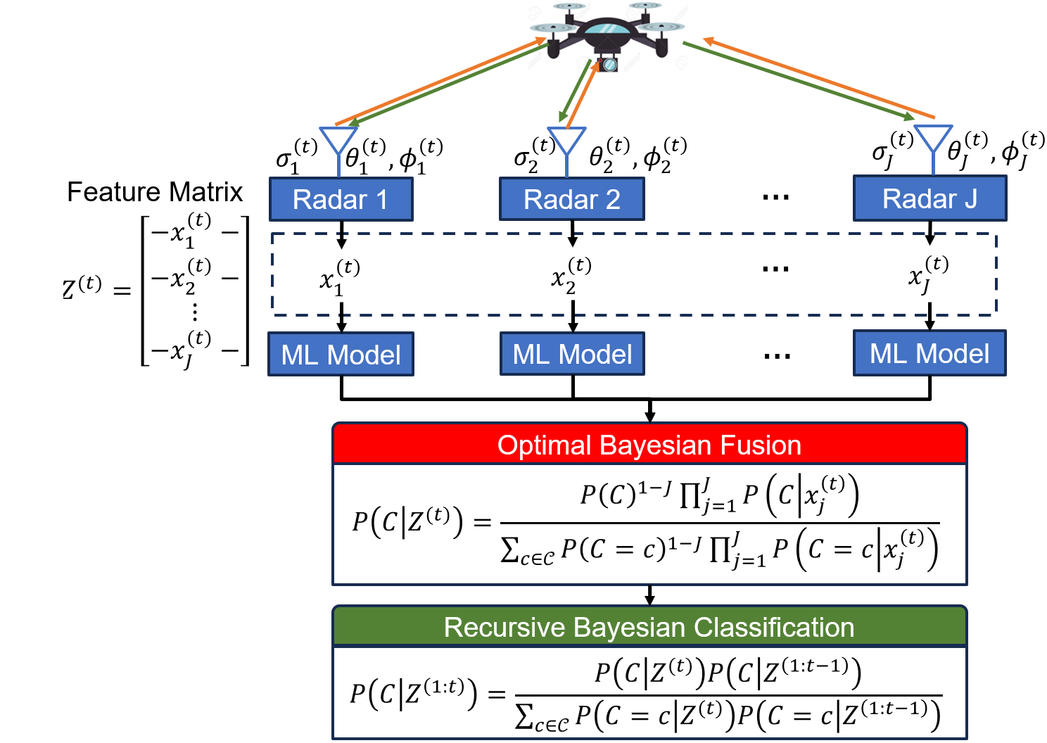
RATR block diagram.
Multiple radars continuously track and pulse an EMW at a moving UAV target.
The each individual radar’s belief about the UAV type is at time step t is fused
in an Bayesian way and used to update recursively a posterior belief about the UAV type.


Multistatic-Radar RCS-Signature Recognition of Aerial Vehicles: A Bayesian Fusion Approach

Michael Potter Northeastern University, Boston, MA 02115, USA  
Murat Akcakaya University of Pittsburgh, Pittsburgh, PA 15260, USA  
Marius Necsoiu DEVCOM ARL, San Antonio, TX 78204, USA 
Gunar Schirner Northeastern University, Boston, MA 02115, USA  
Deniz Erdoğmuş Northeastern University, Boston, MA 02115, USA Tales Imbiriba Northeastern University, Boston, MA 02115, USA

Electrical Engineering and Systems Science > Signal Processing

Radar Automated Target Recognition (RATR) for Unmanned Aerial Vehicles (UAVs) involves transmitting Electromagnetic Waves (EMWs) and performing target type recognition on the received radar echo, crucial for defense and aerospace applications. Previous studies highlighted the advantages of multistatic radar configurations over monostatic ones in RATR.

However, fusion methods in multistatic radar configurations often suboptimally combine classification vectors from individual radars probabilistically. To address this, we propose a fully Bayesian RATR framework employing Optimal Bayesian Fusion (OBF) to aggregate classification probability vectors from multiple radars. OBF, based on expected 0-1 loss, updates a Recursive Bayesian Classification (RBC) posterior distribution for target UAV type, conditioned on historical observations across multiple time steps.

We evaluate the approach using simulated random walk trajectories for seven drones, correlating target aspect angles to Radar Cross Section (RCS) measurements in an anechoic chamber. Comparing against single radar Automated Target Recognition (ATR) systems and suboptimal fusion methods, our empirical results demonstrate that the OBF method integrated with RBC significantly enhances classification accuracy compared to other fusion methods and single radar configurations.
Comments: To be submitted to IEEE Transactions on Aerospace and Electronic Systems
Subjects: Signal Processing (eess.SP); Computer Vision and Pattern Recognition (cs.CV); Machine Learning (cs.LG); Probability (math.PR); Machine Learning (stat.ML)
Cite as: arXiv:2402.17987 [eess.SP]
  (or arXiv:2402.17987v1 [eess.SP] for this version)
  https://doi.org/10.48550/arXiv.2402.17987

Submission history

From: Michael Potter [view email]
[v1] Wed, 28 Feb 2024 02:11:47 UTC (4,323 KB)

arxiv.org

Multistatic-Radar RCS-Signature Recognition of Aerial Vehicles: A Bayesian Fusion Approach

Michael Potter Northeastern University, Boston, MA 02115, USA

Research was sponsored by the Army Research Laboratory and was accomplished under Cooperative Agreement Number W911NF-23-2-0014. The views and conclusions contained in this document are those of the authors and should not be interpreted as representing the official policies, either expressed or implied, of the Army Research Laboratory or the U.S. Government. The U.S. Government is authorized to reproduce and distribute reprints for Government purposes notwithstanding any copyright notation herein.

{IEEEkeywords}

Radar Cross Section, Bayesian Fusion, Unmanned Aerial Vehicles, Machine Learning

1 INTRODUCTION

Radar Automated Target Recognition (RATR) technology has revolutionized the domain of target recognition across space, ground, air, and sea-surface targets [1]. Radar advancements have facilitated the extraction of detailed target feature information, including High Range Resolution Profile (HRRP), Synthetic Aperture Radar (SAR), Inverse Synthetic Aperature Radar (ISAR), Radar Cross Section (RCS) and Micro-Doppler frequency [2]. These features have enabled Machine Learning (ML) and Deep Learning (DL) models to outperform traditional hand-crafted target recognition frameworks [1, 3]. Furthermore, RATR seamlessly integrates with various downstream defense applications such as weapon localization, ballistic missile defense, air surveillance, ground and area surveillance among others [4]. While RATR is applied to various target types, our focus will center on the recognition of Unmanned Aerial Vehicles (UAVs). Henceforth, the terms UAVs and drones will be used interchangeably.

UAVs are a class of aircraft that do not carry a human operator and fly autonomously or are piloted remotely [5]. Historically, UAVs were designed solely for military applications such as surveillance and reconnaissance, target acquisition, search and rescue, and force protection [6, 7]. Recently we have entered the ”Drone Age [8], aka personal glsuav area; where there has been a rapid increase in civilian UAV use for cinematography, tourism, commercial ads, real estate surveying and hot-spot / communications [9, 10].

However, the potential misuse of UAVs poses significant security and safety threats, which is prompting governmental and law enforcement agencies to implement regulations and countermeasures [11, 12]. Adversaries may transport communication jammers with UAVs [13], perform cyber-physical attacks on UAVs (possibly with kill-switches)[14], or conduct espionage via video streaming from UAVs [15]. Criminals may perform drug smuggling, extortion(with captured footage), and cyber attacks (on short-range Wi-Fi, Bluetooth, and other wireless devices) [10]. These security and safety issues are exacerbated by the increased presence of unauthorized and unregistered UAVs [16]. The growing concerns of the new Drone Age, coupled with the increasing nefarious use of UAVs [17], necessitates robust, accurate, and fast RATR frameworks.

Radar systems transmitElectromagnetic Waves (EMWs) directed at a target, and receiving the reflected EMWs (aka radar echoes) [18]. Radar systems are ubiquitous in Automated Target Recognition (ATR) because of the long-range detection capability, ability to penetrate obstacles such as atmospheric conditions, and versatility in capturing detailed target features [18]. Popular radar-based methods of generating target features are ISAR, Micro-Doppler signature, and RCS signatures. ISAR generates high resolution radar images by using the Fourier transform and explotation of the relative motion of the target UAV to create a larger “synthetic” aperture [19]. However, ISAR images degrade significantly when the target UAV has complex motion, such as non-uniform pitching, rolling, and yawing [20]. Micro-Doppler signatures are the frequency modulations around the main Doppler shift due to the UAV containing small parts with additional micro-motions, such as the blade propellers of a drone [21]. However, Micro-Doppler signatures may vanish due to the relative orientation of the drone. Both ISAR and Micro-Doppler require high radar bandwidth for processing and generating target profiles, which is computationally expensive [22, 23]. The RCS of a UAV, measured in dB m2 and proportionate to the received power at the radar, signifies the theoretical area that intercepts incident power; if this incident power were scattered isotropically, then it would produce an echo power at the radar equivalent to that of the actual UAV [24]. RCS signatures have low transmit power requirements, low bandwidth requirements, low memory footprint, and low computational complexity [25, 20]. For these reasons, much of the literature focuses on RCS data collected from transmitted signals with varying carrier frequencies.

Most of the UAV ATR literature using RCS signatures focuses on monostatic radar configurations and does not utilize multiple individual monostatic radar observations at a single time step. However, there are common multistatic radar configuration fusion rules which are based on domain-expert knowledge. The SELection of tX and rX (SELX) fusion rule [26, 27] combines the classification probability vectors from each radar channel via a weighted linear combination, where the weights are higher for the channels with the best range resolution and high Signal-to-Noise-Ratio (SNR). The common SNR fusion rule [28] also combines the classification probability vectors for each radar channel via a weighted linear combination, but the weights proportional to the SNR (higher SNR leads to larger weight). Other works employ heuristic soft-voting, which averages the probability vectors from each radar [29]. However, domain expert’s heuristics may be influenced by cognitive bias or limited by subjective interpretation of experts [30, 31], leading to incorrect conclusions. Furthermore, Bayesian decision rules are known to be optimal decision-making strategies under uncertainty, compared to domain-expert’s heuristic-based decisions [32, 33].

Our Contributions of this work: To the best of our knowledge, this work is the first to provide a fully Bayesian RATR framework for UAV type classification from RCS time series data. We employ an Optimal Bayesian Fusion (OBF) method, which is the Bayesian fusion method for optimal decisions with respect to 0-1 loss, to formulate a posterior distribution from multiple individual radar observations at a given time step. This optimal method is then used to update a separate Recursive Bayesian Classification (RBC) posterior distribution on the target UAV type, conditioned on all historical observations from multiple radars over time.

Thus, our approach facilitates efficient use of training data, informed classification decisions based on Bayesian principles, and enhanced robustness against increased uncertainty. Our method demonstrates a notable improvement in classification accuracy, with relative percentage increases of 35.71% and 14.14% at an SNR of 0 dB compared to single radar and RBC with soft-voting methods, respectively. Moreover, our method achieves a desired classification accuracy (or correct individual prediction) in a shorter dwell time compared to single radar and RBC with soft-voting methods

The paper is structured as follows: Section II describes the related work for RATR on RCS data; Section III details the data, data simulation and dataset structure; Section IV explains the OBF method and RBC for our RATR framework; Section V discusses the experiment configuration and results; Section VI derives conclusions on our findings.

2 RELATED WORK

We sort the literature on RATR target recognition models into two types: statistical ML and DL.

Statistical ML: Many methods leverage generative probabilistic models using Bayes Theorem to classify a target UAV based on the highest class conditional likelihood [34, 20, 35]. The method in [34, 20] classified commercial drones with generative models such as Swerling (1-4), Gamma, Gaussian Mixture Model (GMM) and Naive Bayes on multiple independent RCS observations simulated from an monostatic radar in an anechoic chamber. However, there could potentially exist a hidden temporal relationship among the RCS observations. In the study of [36], unspecified aircrafts were classified based on RCS time series data using an Hidden Markov Model (HMM) fitted with the Viterbi algorithm. In this model, the hidden state represented the contiguous angular sector of the UAV-radar orientation, with the observations comprising RCS measurements. While generative models are designed to capture the joint distribution of both data and class labels, this approach proves computationally inefficient and overly demanding on data when our primary goal is solely to make classification decisions [37].

Refer to caption
Figure 1: M100 HH polarization RCS signature images from the Indoor Near Field experiments from [38]

Discriminative ML models directly find the posterior probability on the UAV type given RCS data, and have been used in RATR for UAV type classification [34, 39, 40, 41]. The study described in [41] employed summary statistics of RCS time series data to classify between UAV and non-UAV tracks, utilizing both Multi Layer Perceptron (MLP) and Support Vector Machine (SVM) models. However, Ezuma et al showed that Tree-based classifiers outperformed generative, other discriminative ML models (such as SVM, K - Nearest Neighbors (KNN), and ensembles), and deep learning models [34]. Furthermore, [42] showed Random Forests significantly outperform SVM when classifying commercial drones using micro-Doppler signatures derived from simulated RCS time series data [40]. While these methods demonstrate high classification accuracy in monostatic radar experiments, they do not take advantage of or account for multistatic radar configurations. Instead of consolidating all the features from multiple RCS observations into a large input space, it is more effective to construct individual models for each time slice or radar viewpoint [37]. We now shift our focus to DL methods, acknowledging the undeniable ascent of DL [43, 44].

DL: The enhanced capability of radar to extract complex target features has sparked an increasing demand for models capable of using complex data, exemplified by the rising use of DL model [28, 1]. The work in [45] was the first application of Convolutional Neural Network (CNN) for monostatic radar classification based on simulated RCS time series data of geometric shapes. However, CNNs do not incorporate long-term temporal dynamics into their modeling approach. To address this limitation and capture long-term and short term temporal dynamics, many studies have used Recurrent Neural Networks (RNNs) and Long Short Term Memorys (LSTMs) networks [46]. These works classify a sliding time window or the entire trajectory of RCS time series data corresponding to monostatic radars tracking an UAV [47, 48, 49]. [50] combined a bidirectional Gated Recurrent Unit (GRU) RNN and a CNN to extract features from RCS time series data of geometric shapes and small-sized planes, subsequently using an Feed Forward Neural Network (FFNN) for classification. Lastly, [29] employed a spatio-temporal-frequency Graph Neural Network (GNN) with RNN aggregation to classify two simulated aircraft with different micromotions tracked by a synthetic heterogeneous distributed radar system. While numerous DL approaches have been utilized in RCS based RATR classification frameworks, challenges still persist, including the necessity for substantial data to generalize to unseen data [51], overconfident predictions [52], and a lack of interpretability [53]. Furthermore, Ezuma et al showed that Tree-based ML models outperformed traditional deep complex Neural Network (NN) architectures for commercial drone classification. Thus this paper focuses on the following ML models: Extreme Gradient Boosting (XGBoost), MLP with three hidden layers, and logistic regression.

3 Multi-Static RCS Dataset Generation

This section outlines the process of mapping simulated azimuth and elevation angles to RCS data measured in an anechoic chamber. This involves calculating the target UAV aspect angles (azimuth and elevation) relative to the Radar Line Of Sight (RLOS) while considering the target UAV pose (yaw γ, pitch α, roll β and translation T). The pose of the target UAV will change over time as a function of a random walk kinematic model.
Refer to caption
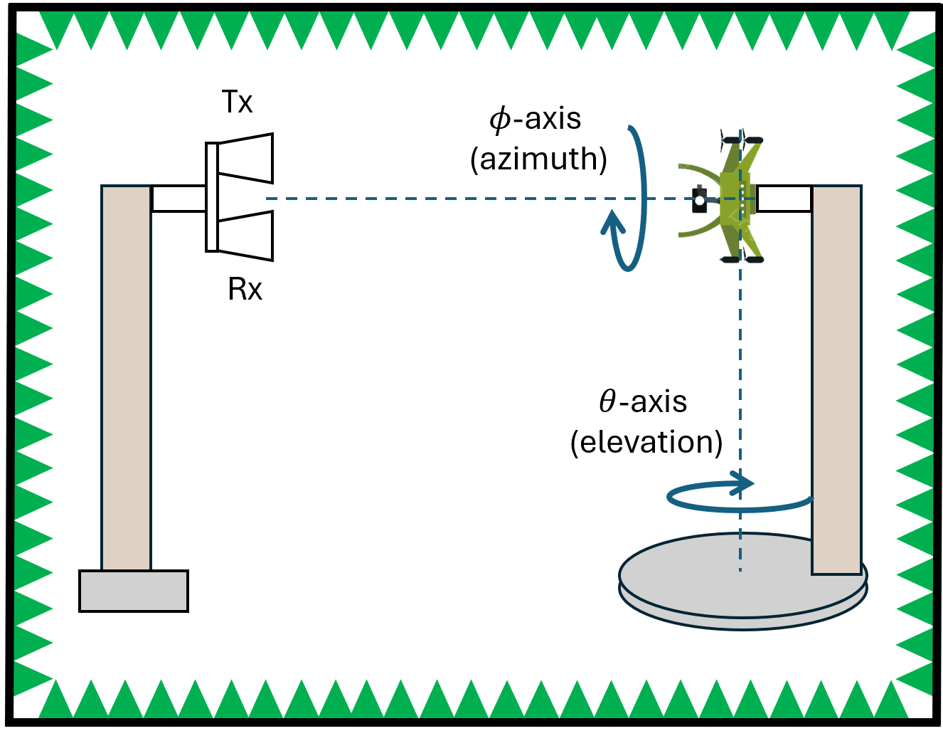
Figure 2: Indoor Near Field RCS signature collection utilizing different polarization combinations of EMW signals transmitted and received from from quasi-monstatistc radar.

3.1 Existing Data

We analyze the approximate RCS signatures of 7 different UAVs collected in [38]: the F450, Heli, Hexa, M100, P4P, Walkera, and Y600 . The data was collected in an anechoic chamber, where a quasi-monostatic radar transmitted EMWs at F=15 frequencies (26-40 GHz in 1 GHz steps) while stepped motors rotated the UAV around the azimuth axis (ϕ in Figure 2) and the elevation axis (θ in Figure 2) [38]. The azimuth spans from 0 to 180 degrees, while the elevation extends from -95 to 95 degrees, both in 1-degree increments. An example of the RCS image of a UAV from [38] is shown in Figure 1. We leverage the real RCS signatures to create training and testing datasets corresponding to simulated/synthetic radar locations and drone trajectories.

3.2 Training Data Generation

We sample azimuth and elevation uniformly at random, where the spread is bounded by each drone’s minimum and maximum aspect angles from the experimental setup in [38]. The azimuth and elevation samples, ϕ and θ respectively, are mapped to a measured RCS signature σF from [38], where we linearly interpolate the mapped RCS measurements for continuous azimuth and elevations not collected in [38]. For each UAV type c𝒞train=[1,,7], we generate Ntrain samples such that |𝒟train|=|𝒞train|Ntrain. Training a discriminative ML classifier under the perspective of a single radar at a single time point enables efficient sampling and training. Generating training data for multistatic radar configurations would deal with the curse of dimensionality, where trajectories (a sample trajectory being multiple time points concatenated) compounded with multiple radars would exponentially increase the required number of samples to adequately cover the input space. In summary, the training dataset 𝒟train has the following structure:


𝒟train={(xi,ci)}i=1Ntrain
(1)

where xi(t)=[σi(t),ϕi(t),θi(t)] contains the noisy RCS signature, the noisy azimuth and the noisy elevation. The noisy RCS signature, azimuth, and elevation will be discussed in Section 3.
Refer to caption
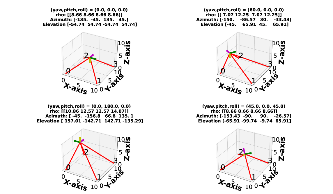
Figure 3: Example which illustrates the RLOS between multiple radars (4) and a single target. The radar positions are the red markers numbered (0-3). The x-axis, y-axis, and z-axis of the target UAV coordinate frame are the green, magenta, and yellow arrows respectively the target UAV position and coordinate frame is randomly simulated using translation, yaw, pitch, and roll homogeneous matrices.

3.3 Testing Data Generation

We generate time series data of azimuth, elevation, and the corresponding RCS signature by simulating multiple RLOS to a target UAV being tracked for L=100 time steps along random walk trajectories. For each UAV type c𝒞test, we generate Ntest trajectories such that |𝒟test|=|𝒞test|Ntest. The target UAV trajectory follows a kinematic model of a drone moving at constant velocity vx=50[m/s] with random yaw and roll rotation jitters at a time resolution of Δt=0.1 seconds:


d(t) =Rγ(t1)Rα(t1)Rβ(t1)ex
(2)

𝒰(t) =𝒰d(t1)+vxΔtd(t)
(3)

γ(t) =γ(t1)+ϵγ; ϵβ𝒩(0,144)
(4)

α(t) =0
(5)

β(t) =β(t1)+ϵβ; ϵβ𝒩(0,81)
(6)

where the positive x-axis of the target UAV coordinate frame is the UAV ”forward facing” direction, ex is the x-axis unit vector, and 𝒰 is the UAV position. The initial position and yaw of the target UAV is sampled uniformly at random:


γ(0) U(0,2π)
(7)

𝒰d(t1) [U(150,150),U(150,150),U(200,300)]T
(8)

where the initial pitch and roll is 0.

Subsequently, at every time step t, the radars’ coordinate frames are transformed from the world coordinate frame to target coordinate frame:


[Δx(t)Δy(t)Δz(t)]=Rα(t)1Rβ(t)1Rγ(t)1(T(t))1𝒫
(12)

𝒫=[p1,p2pJ]
(13)

where pj is the world coordinates of radar j. The azimuth and elevation corresponding to each RLOS are found by converting from Cartesian coordinates to Spherical coordinates:


ρ(t)=(Δx(t))2+(Δy(t))2+(Δz(t))2
(14)

ϕ(t)=arctan(Δy(t)Δx(t))
(15)

θ(t)=δ(Δx(t)<0)arccos(Δz(t)ρ(t))
(16)

where ρ is the length of the RLOS to the target UAV. A single time step of a simulated UAV being tracked by multiple individual radars is depicted in Figure 3, featuring the displayed azimuths and elevations. The simulated azimuth and elevation time series data, ϕ(1:t)L×J and θ(1:t)L×J respectively, is mapped to the measured RCS time series data z(1:t)L×(JF). Due to the symmetry of the drones, the measured RCS for any azimuth not between [0,180] is approximated as the RCS corresponding to ϕ=ϕ+180. We note a negative Δz is used to align our target UAV coordinate frame with the experimental setup in [38], where the azimuth and elevation are calculated with respect to the bottom of the drone.

In summary, the test dataset 𝒟test has the following structure:


𝒟test={(zi(1:L),ci)}i=1Ntest
(17)

where zi(t)=[xi1(t),xi2(t),,xiJ(t)]T and i denotes the sample index and j the radar index.

We train the discriminative ML model on the RCS, azimuth, and elevation measurements described in Section 3 Subsection 3.2, and evaluate our RATR framework on the trajectories described in Section 3 Subsection 3.3. We next discuss how these discriminative ML models are integrated into the RATR framework.

4 METHODOLOGY

At each time step t multiple radars pulse EMWs at the target UAV, where each radar j calculates a RCS signature, azimuth, and elevation xj. Each radar inputs its respective observation to a local discriminative ML model to output a UAV type probability vector. Here, local denontes that the ML resides at the individual radar hardware. All the individual radar UAV type probability vectors are combined by a fusion method (Section 4 Subsection 4.2). Subsequently, the posterior UAV type probability distribution, based on the past RCS signatures z(1:t1), is updated with the fused UAV type probability distribution from time step t. A RBC framework is applied such that the posterior probability distribution recursively updates as the radars continuously track a moving UAV. Our framework is shown in Figure 4.

Refer to caption
Figure 4: RATR block diagram. Multiple radars continuously track and pulse an EMW at a moving UAV target. The each individual radar’s belief about the UAV type is at time step t is fused in an Bayesian way and used to update recursively a posterior belief about the UAV type.

We focus on three discriminative ML models to generate individual radar UAV type probability vectors, which is described in the next subsection.

4.1 ML Models

In Logistic Regression, the model estimates the posterior probabilities of |𝒞| classes parametrically through linear functions in x. It adheres to the axioms of probability, providing a robust framework for probabilistic classification [54]. The MLP, on the other hand, is a parametric model which estimates a highly nonlinear function. We use a FFNN architecture, where each neuron in the network involves an affine function of the preceding layer output, coupled with a nonlinear activation function (e.g., leaky-relu), with the exception of the last layer. For Logistic Regression and MLP, we use the Python Scikit-learn Python package LogisticRegression and MLPClassifier modules respectively; with the default hyperparameters (except the hidden layer size hyperparameter of [50,50,50]) [55]. XGBoost is a powerful non-parametric model that utilizes boosting with decision trees. In this ensemble method, each tree is fitted based on the residual errors of the previous trees, enhancing the model’s overall predictive capability [56]. We use the Python XGBoost package XGBClassifier module with the default hyperparameters [57].

4.2 Fusion Methods

The probability distribution P(C|Z(t)) can leverage existing ML discriminative classification algorithms, including but not limited to as XGBoost, MLP, and Logistic Regression. For each ML model, we benchmark several radar RCS fusion methodologies: OBF, average, and maximum.
Refer to caption
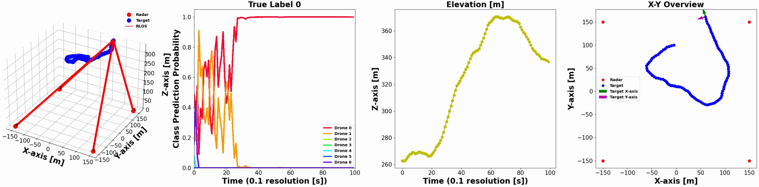
Figure 5: One data sample from the training test data is shown for illustrative purposes. The first subfigure (from the left) depicts four uniformly spaced radars tracking and classifying a target UAV navigating with a random walk trajectory. The second subfigure illustrates the evolution of the RBC posterior probability for the UAV type over time as more RCS, azimuth, and elevation measurements are collected. The third and fourth figures display the change in elevation from ground level and the top view of the X-Y position of the UAV over time, respectively.

4.2.1 Bayesian Optimal Fusion

The optimal fusion rule of the joint posterior distribution p(C(t)|Z(t)) is presented in [58, 37] as


P(C|Z(t))=P(C)(1J)j=1JP(C|xj(t))c=1𝒞P(C=c)(1J)j=1JP(C=c|xj(t))
(18)

The OBF method combines the individual radar probability vectors probabilistically, where the key assumption is conditional independence of the multiple individual radar observations at time step t for a given UAV type: P(x1(t),x2(t),,xJ(t)|C=c)=j=1JP(C|xj(t))

4.2.2 Random

We use random classification probability vectors for the fusion method as a baseline of comparison. We denote the fused classification probability of J individual radars as a sample from the Dirichlet Distribution P(C|Z(t))Dir(1|𝒞|), which is equivalent to uniformly at random sampling from the simplex of discrete probability distributions.

4.2.3 Hard-Voting

Hard-voting involves selecting the UAV type that corresponds to the mode of decisions made by each individual radar discriminative ML model regarding UAV types [59].


P(C=c|Z(t))={1|𝒞|ϵ|𝒞|+1if c=Mo(c1^,,cJ^)ϵ|𝒞|otherwise
(19)

where Mo denotes the mode function and cj^ denotes the maximum probability UAV type for radar j.

4.2.4 Soft-Voting

Soft-voting is the average of multiple individual ML model probability vectors. The UAV type with the highest average probability across all probability vectors is the final predicted UAV type. Averaging accounts for the confidence levels of each individual model, which provides a more nuanced method than hard-voting.


P(C|Z(t))=1Jj=1JP(C=c|xj(t))
(20)

To benchmark our methodology, each individual radar operates within the same noisy channel (maintaining identical SNR) as they are closely geolocated. Consequently, the fusion method employed in this setup is analogous to the SNR fusion rule [28].

4.2.5 Maximum

We take the maximum (max) class probability over multiple individual ML models. The max operator over random variables is known to be biased towards larger values, which will lead to worse classification performance [60].


P(C|Z(t))=maxjP(C=c|xj(t))
(21)

For each of the previously described fusion methods, when a new RCS measurement at time t is observed, the fused UAV type probability distribution updates the recursively estimated UAV type posterior distribution.

4.3 Recursive Bayesian Classification

RBC with the OBF provides a principled framework for Bayesian classification on time-series data. As the radars’ dwell time on an individual target increases, the uncertainty and accuracy in the UAV type will decrease and increase respectively due to increased number of data observations. Furthermore, Bayesian methods are robust to situations with noisy data, which is common in radar applications (high clutter environments, multi-scatter points, and multi-path propagation). The RBC posterior probability for the UAV types is derived:


P(C|Z(1:t)) =P(Z(t)|C)P(C|Z(1:t1))c=1𝒞P(Z(t)|C=c)P(C=c|Z(1:t1))


=P(C|Z(t))P(Z(t))P(C|Z(t))P(Z(t))P(C|Z(1:t1))c=1𝒞P(C=c|Z(t))P(Z(t))P(C=c|Z(t))P(Z(t))P(C=c|Z(1:t1))


=P(C|Z(t))P(C|Z(1:t1))c=1𝒞P(C=c|Z(t))P(C=c|Z(1:t1))
(22)

where we approximate the marginal distribution P(C)=P(C|Z(t))P(Z(t))𝑑Z(t) as a prior distribution, 1K, following previous papers [61, 62].

Next, we outline our approach to benchmarking the integration of the OBF method with the RBC within our RATR framework, establishing a fully Bayesian target recognition approach.
Refer to caption
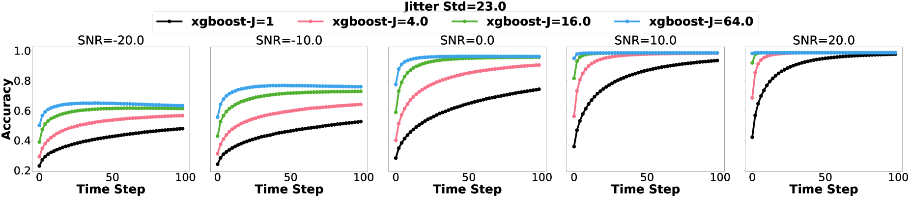
Figure 6: The RBC accuracy performance versus the number of radars increasing as a power of 2 (4, 16, 64 radars) for each discriminative ML model. The subfigures from left to the right increase the SNRdB and the term J in the legend denotes the number of radars in a surveillance area.

5 EXPERIMENTS

In the following subsections, we will describe the experimental setup and the assumptions made in our study to evaluate the performance of our proposed RATR for UAV type classification. We perform 10 Monte Carlo trials for each experiment and report the respective average accuracy. Through comprehensive analysis, we elucidate the impact of varying SNR levels and fusion methodologies on RATR.

5.1 Configuration

All experiments were run on Dual Intel Xeon E5-2650@2GHz processors with 16 cores and 128 GB RAM. The training dataset and the testing dataset sizes are 10000 samples and 2000 samples respectively. We make the follow assumptions in our simulations of multistatic radar for single UAV type classification:

  1. multiple radar systems transmit and receive independent signals (non-interfering constructively or destructively) using time-division multiplexing,

  2. multiple radar systems continuously track a single UAV during a dwell time of 10 seconds (Figure 5 leftmost figure),

  3. the azimuth and elevation of the incident EMW may be recovered with noise,

  4. use of Additive Colored Gaussian Noise (ACGN) for the RCS signatures and uniform noise for the azimuth and elevations for noisy observations and

  5. the J radars are uniformly spaced in a 900m2 grid on the ground level (Figure 5 leftmost figure).

We analyze radar configurations under various scenarios, including uniform radar spacing and a single radar placed at the (-150 [m], -150 [m]) corner of the grid. Randomly positioning radars within an boxed-area is excluded to prevent redundant stochastic elements, given the inherent randomness in the drone trajectories. Our investigation focuses on radar fusion method performance across various SNR settings and the number of radars in the multistatic configuration.

5.2 Signal-to-Noise Ratio

We apply ACGN to the measured RCS such as [34], but the units of the RCS signatures are dBm2 units. The colored covariance matrix is generated as an outer product of a randomly sampled matrix of rank F:


M𝒩(0,IF)
(23)

Σ=MMT
(24)

For each observed RCS signature σi* at time step t and a specified SNR, we calculate the required noise power of the ACGN:


Tr(Σi)=fσi*(f)210SNR10
(25)

where the trace of the covariance matrix is the total variance. We subsequently scale the covariance matrix to attain the desired SNR for sample i,


Σi=ΣiTr(Σi)fσi*(f)210SNR10
(26)

and then add a sample realization of the ACGN to the observed RCS signature:


σi=σi*+ϵ ϵ𝒩(0,Σi)
(27)

Additionally, to satisfy our third assumption of recovering the azimuth and elevation with noise, we add jitter uniformly at random to the ground truth azimuth and elevation with:


uϕ,uθ Uϕ(aϕ,aϕ),Uθ(aθ,aθ)
(28)

ϕ=ϕ*+uϕθ=θ*+uθ
(29)

where aϕ and aθ determine the variance of uniform noise. We expect that our fully Bayesian RATR for UAV type will be more robust to low SNR environments.

5.3 Results

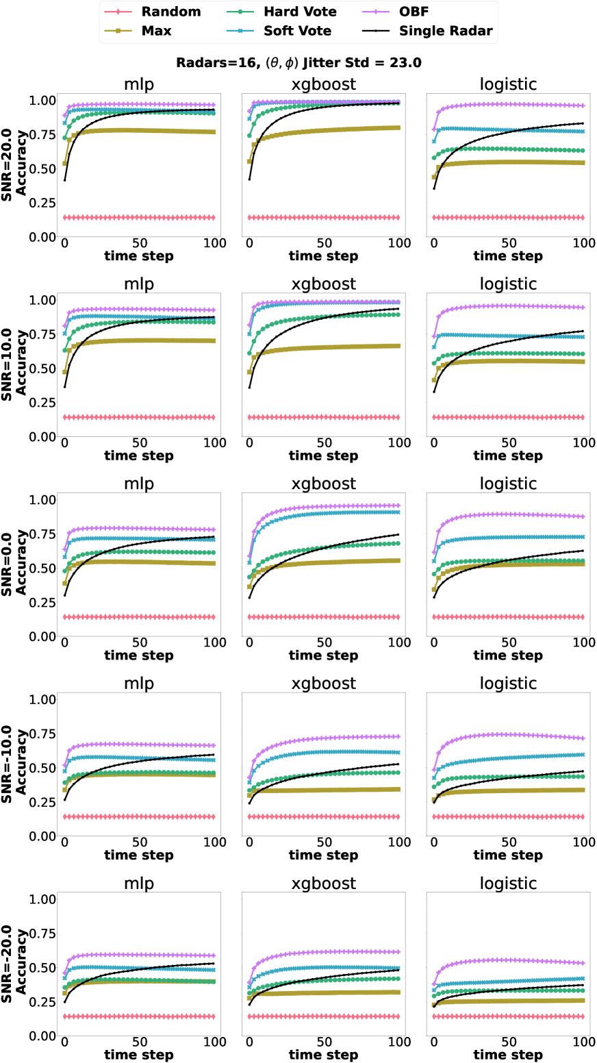
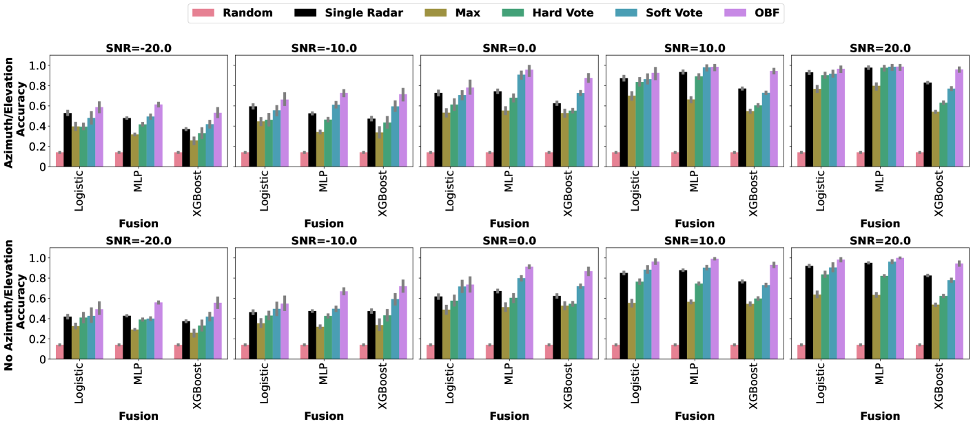
Using the optimal fusion method, namely the OBF method, results in substantial classification performance improvement in multistatic radar configurations compared to a single monostatic radar configurations (Figure 8,Figure 7).
Refer to caption
Figure 7: Each figure axis specifies the SNR, with the first row displaying results with azimuth and elevation having a jitter standard deviation of 23, and the second row displaying results without azimuth and elevation. The bar color represents different fusion methods, and the line atop the bar indicates the 95% confidence interval over 10 Monte Carlo trials. All results are for 16 radars in a multistatic configuration, except single radar.
Refer to caption
Figure 8: Each figure axis, where each row specifies the SNR and each column specifies the ML model, plots the RBC accuracy over time of 16 radars (and a single radar) for the OBF, soft-voting, hard-voting, single radar, and maximum fusion methods. The azimuth and elevation jitter standard deviations was 23.

However, when using a fusion method not rooted in Bayesian analysis, such as the common SNR fusion rule, a single radar may outperform or exhibit similar classification performance in multistatic radar configurations provided there is a sufficient dwell time (Figure 8, the column of MLP and the column of Logistic Regressionand Figure 7). We also observed for the single radar and other fusion methods that various combinations of discriminative ML models and SNRs plateau at substantially lower classification accuracy compared to the OBF (Figure 8).

Increasing the number of radars within a surveillance area increases the different geometric views of the UAV, therefore providing a diverse UAV RCS signature at a specific time step t. We see that as the number of radars increases, the classification performance also increases under various SNR environments (Figure 6). Furthermore, increasing the number of radars in a surveillance area allows correctly classifying the target UAV type in a shorter period of time (on average).

We visualize the RBC accuracy as the SNR changes (Figure 7). We observe an ”S” curve by following the top of the barplot across columnns of figure axes, where an increase in the signal power does not lead to an increase in classification performance at the upper extremes of SNR. However, radar channels typically operate in the 0 to -20 dB SNR range. When the RATR is operating at lower SNR ranges, having more observations of the target UAV substantially improves the classification performance versus a single radar (Figure 6). If the SNR is high, the classification performance of a single radar should approach that of multi-radar classification, given a sufficiently large dwell time and suitable target geometries, especially when using a complex ML model (Figure 8).

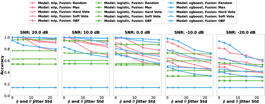
We assumed that azimuth and elevation of the incident EMW directed at the target UAV could be recovered for each radar, albeit with some noise. In the case of Logistic Regression, azimuth and elevation information does not seem to impact the classification decision. Increasing the standard deviation of the uniform noise jitter does not impact the classification accuracy. However, nonlinear discriminative ML models, such as MLP and XGBoost, leverage the interactions between the RCS signatures and the received azimuths and elevations, resulting in improved classification performance. Thus, for MLP and XGBoost, we observe that an increase in the standard deviation of uniform noise for azimuth and elevation leads to a decrease on the classification performance for lower SNR environments (Figure 9).
Refer to caption
Figure 9: Each subfigure is the RBC accuracy for 16 radars versus the azimuth and elevation standard deviation of the uniform distribution. The subfigures from left to the right decrease the SNRdB. Each line color denotes a different discriminative ML model, and the line marker denotes the fusion method.

As an ablation study, we completely remove the azimuth and elevation information from the discriminative ML model training and inference. We observe that multistatic radar configurations still significantly improve RBC classification performance, and the OBF method remains the most effective fusion method (Figure 7).

6 CONCLUSION

This paper is the first to introduce a fully Bayesian RATR for UAV type classification in multistatic radar configurations using RCS signatures. We evaluated the classification accuracy and robustness of our method across diverse SNR settings using RCS, azimuth, and elevation time series data generated by random walk drone trajectories. Our empirical results demonstrate that integrating the OBF method with RBC in multistatic radar signifcantly enhances ATR. Additionally, our method exhibits greater robustness in lower SNR, with larger relative improvements observed compared to single monostatic radar and other non-trivial fusion methods. Thus, fully Bayesian RATR in multistatic radar configurations using RCS signatures improves both classification accuracy and robustness.

Future work will integrate radar-based domain-expert knowledge with Bayesian analysis, such that our method may incorporate radar parameters such as the range resolution or estimated SNR.

References


[1] W. Jiang, Y. Wang, Y. Li, Y. Lin, and W. Shen, “Radar target characterization and deep learning in radar automatic target recognition: A review,” Remote Sensing, vol. 15, no. 15, p. 3742, 2023.
[2] J. Eaves and E. Reedy, Principles of modern radar.   Springer Science & Business Media, 2012.
[3] X. Cai, M. Giallorenzo, and K. Sarabandi, “Machine learning-based target classification for mmw radar in autonomous driving,” IEEE Transactions on Intelligent Vehicles, vol. 6, no. 4, pp. 678–689, 2021.
[4] A. K. Maini, Military Radars, 2018, pp. 203–294.
[5] H. Learning. Unmanned aircraft systems / drones. [Online]. Available: https://rmas.fad.harvard.edu/unmanned-aircraft-systems-drones
[6] M. W. Lewis, “Drones and the boundaries of the battlefield,” Tex. Int’l LJ, vol. 47, p. 293, 2011.
[7] P. Mahadevan, “The military utility of drones,” CSS Analyses in Security Policy, vol. 78, 2010.
[8] D. Beesley, “Head in the clouds: documenting the rise of personal drone cultures,” Ph.D. dissertation, RMIT University, 2023.
[9] H. Shakhatreh, A. H. Sawalmeh, A. Al-Fuqaha, Z. Dou, E. Almaita, I. Khalil, N. S. Othman, A. Khreishah, and M. Guizani, “Unmanned aerial vehicles (uavs): A survey on civil applications and key research challenges,” IEEE Access, vol. 7, pp. 48 572–48 634, 2019.
[10] J.-P. Yaacoub, H. Noura, O. Salman, and A. Chehab, “Security analysis of drones systems: Attacks, limitations, and recommendations,” Internet of Things, vol. 11, p. 100218, 2020.
[11] E. Bassi, “From here to 2023: Civil drones operations and the setting of new legal rules for the european single sky,” Journal of Intelligent & Robotic Systems, vol. 100, pp. 493–503, 2020.
[12] T. Madiega, “Artificial intelligence act,” European Parliament: European Parliamentary Research Service, 2021.
[13] M. Elgan. Why consumer drones represent a special cybersecurity risk. [Online]. Available: https://securityintelligence.com/articles/why-consumer-drones-represent-a-special-cybersecurity-risk/
[14] J. Villasenor. Cyber-physical attacks and drone strikes: The next homeland security threat. [Online]. Available: https://www.brookings.edu/articles/cyber-physical-attacks-and-drone-strikes-the-next-homeland-security-threat/
[15] Y. Mekdad, A. Aris, L. Babun, A. El Fergougui, M. Conti, R. Lazzeretti, and A. S. Uluagac, “A survey on security and privacy issues of uavs,” Computer Networks, vol. 224, p. 109626, 2023.
[16] F. A. Administration. Uas sightings report. [Online]. Available: https://www.faa.gov/uas/resources/public_records/uas_sightings_report
[17] G. Markarian and A. Staniforth, Countermeasures for aerial drones.   Artech House, 2020.
[18] M. A. Richards, J. Scheer, W. Holm, and W. Melvin, “Principles of modern radar, raleigh, nc,” 2010.
[19] V. Chen and M. Martorella, “Inverse synthetic aperture radar,” SciTech Publishing, vol. 55, p. 56, 2014.
[20] M. Ezuma, C. K. Anjinappa, M. Funderburk, and I. Guvenc, “Radar cross section based statistical recognition of uavs at microwave frequencies,” IEEE Transactions on Aerospace and Electronic Systems, vol. 58, no. 1, pp. 27–46, 2022.
[21] C. Clemente, A. Balleri, K. Woodbridge, and J. J. Soraghan, “Developments in target micro-doppler signatures analysis: radar imaging, ultrasound and through-the-wall radar,” EURASIP Journal on Advances in Signal Processing, vol. 2013, no. 1, pp. 1–18, 2013.
[22] P. Klaer, A. Huang, P. Sévigny, S. Rajan, S. Pant, P. Patnaik, and B. Balaji, “An investigation of rotary drone herm line spectrum under manoeuvering conditions,” Sensors, vol. 20, no. 20, p. 5940, 2020.
[23] V. C. Chen, The micro-Doppler effect in radar.   Artech house, 2019.
[24] A. Manikas. Ee3-27: Principles of classical and modern radar: Radar cross section (rcs) & radar clutter. [Online]. Available: https://skynet.ee.ic.ac.uk/notes/Radar_4_RCS.pdf
[25] L. M. Ehrman and W. D. Blair, “Using target rcs when tracking multiple rayleigh targets,” IEEE Transactions on Aerospace and Electronic Systems, vol. 46, no. 2, pp. 701–716, 2010.
[26] P. Stinco, M. Greco, F. Gini, and M. La Manna, “Nctr in netted radar systems,” in 2011 4th IEEE International Workshop on Computational Advances in Multi-Sensor Adaptive Processing (CAMSAP), 2011, pp. 301–304.
[27] P. Stinco, M. Greco, F. Gini, and M. L. Manna, “Multistatic target recognition in real operational scenarios,” in 2012 IEEE Radar Conference, 2012, pp. 0354–0359.
[28] T. Derham, S. Doughty, C. Baker, and K. Woodbridge, “Ambiguity functions for spatially coherent and incoherent multistatic radar,” IEEE Transactions on Aerospace and Electronic Systems, vol. 46, no. 1, pp. 230–245, 2010.
[29] H. Meng, Y. Peng, W. Wang, P. Cheng, Y. Li, and W. Xiang, “Spatio-temporal-frequency graph attention convolutional network for aircraft recognition based on heterogeneous radar network,” IEEE Transactions on Aerospace and Electronic Systems, vol. 58, no. 6, pp. 5548–5559, 2022.
[30] D. J. Koehler, L. Brenner, and D. Griffin, “The calibration of expert judgment: Heuristics and biases beyond the laboratory,” Heuristics and biases: The psychology of intuitive judgment, pp. 686–715, 2002.
[31] E. C. Yu, A. M. Sprenger, R. P. Thomas, and M. R. Dougherty, “When decision heuristics and science collide,” Psychonomic bulletin & review, vol. 21, pp. 268–282, 2014.
[32] J. Q. Smith, Bayesian decision analysis: principles and practice.   Cambridge University Press, 2010.
[33] J. Baron, “Heuristics and biases,” The Oxford handbook of behavioral economics and the law, pp. 3–27, 2014.
[34] M. Ezuma, C. K. Anjinappa, V. Semkin, and I. Guvenc, “Comparative analysis of radar cross section based uav classification techniques,” arXiv preprint arXiv:2112.09774, 2021.
[35] A. Register, W. Blair, L. Ehrman, and P. K. Willett, “Using measured rcs in a serial, decentralized fusion approach to radar-target classification,” in 2008 IEEE Aerospace Conference, 2008, pp. 1–8.
[36] H. Cho, J. Chun, T. Lee, S. Lee, and D. Chae, “Spatiotemporal radar target identification using radar cross-section modeling and hidden markov models,” IEEE Transactions on Aerospace and Electronic Systems, vol. 52, no. 3, pp. 1284–1295, 2016.
[37] C. Bishop, “Pattern recognition and machine learning,” Springer google schola, vol. 2, pp. 531–537, 2006.
[38] V. Semkin, J. Haarla, T. Pairon, C. Slezak, S. Rangan, V. Viikari, and C. Oestges, “Drone rcs measurements (26-40 ghz),” 2019. [Online]. Available: https://dx.doi.org/10.21227/m8xk-dr55
[39] A. Rawat, A. Sharma, and A. Awasthi, “Machine learning based non-cooperative target recognition with dynamic rcs data,” in 2023 IEEE Wireless Antenna and Microwave Symposium (WAMS), 2023, pp. 1–5.
[40] V. Semkin, M. Yin, Y. Hu, M. Mezzavilla, and S. Rangan, “Drone detection and classification based on radar cross section signatures,” in 2020 International Symposium on Antennas and Propagation (ISAP), 2021, pp. 223–224.
[41] N. Mohajerin, J. Histon, R. Dizaji, and S. L. Waslander, “Feature extraction and radar track classification for detecting uavs in civillian airspace,” in 2014 IEEE Radar Conference, 2014, pp. 0674–0679.
[42] L. Lehmann and J. Dall, “Simulation-based approach to classification of airborne drones,” in 2020 IEEE Radar Conference (RadarConf20), 2020, pp. 1–6.
[43] I. Goodfellow, Y. Bengio, and A. Courville, Deep Learning.   MIT Press, 2016, http://www.deeplearningbook.org.
[44] L. Deng, “Artificial intelligence in the rising wave of deep learning: The historical path and future outlook [perspectives],” IEEE Signal Processing Magazine, vol. 35, no. 1, pp. 180–177, 2018.
[45] E. Wengrowski, M. Purri, K. Dana, and A. Huston, “Deep cnns as a method to classify rotating objects based on monostatic RCS,” IET Radar, Sonar & Navigation, vol. 13, no. 7, pp. 1092–1100, 2019.
[46] C. M. Bishop and H. Bishop, “The deep learning revolution,” in Deep Learning: Foundations and Concepts.   Springer, 2023, pp. 1–22.
[47] J. Mansukhani, D. Penchalaiah, and A. Bhattacharyya, “Rcs based target classification using deep learning methods,” in 2021 2nd International Conference on Range Technology (ICORT).   IEEE, 2021, pp. 1–5.
[48] B. Sehgal, H. S. Shekhawat, and S. K. Jana, “Automatic target recognition using recurrent neural networks,” in 2019 International Conference on Range Technology (ICORT).   IEEE, 2019, pp. 1–5.
[49] R. Fu, M. A. Al-Absi, K.-H. Kim, Y.-S. Lee, A. A. Al-Absi, and H.-J. Lee, “Deep learning-based drone classification using radar cross section signatures at mmwave frequencies,” IEEE Access, vol. 9, pp. 161 431–161 444, 2021.
[50] S. Zhu, Y. Peng, and G. C. Alexandropoulos, “Rcs-based flight target recognition using deep networks with convolutional and bidirectional gru layer,” in Proceedings of the 2020 the 4th International Conference on Innovation in Artificial Intelligence, 2020, pp. 137–141.
[51] M. A. Bansal, D. R. Sharma, and D. M. Kathuria, “A systematic review on data scarcity problem in deep learning: solution and applications,” ACM Computing Surveys (CSUR), vol. 54, no. 10s, pp. 1–29, 2022.
[52] A. Immer, M. Korzepa, and M. Bauer, “Improving predictions of bayesian neural nets via local linearization,” in International conference on artificial intelligence and statistics.   PMLR, 2021, pp. 703–711.
[53] D. Castelvecchi, “Can we open the black box of ai?” Nature News, vol. 538, no. 7623, p. 20, 2016.
[54] T. Hastie, R. Tibshirani, J. H. Friedman, and J. H. Friedman, The elements of statistical learning: data mining, inference, and prediction.   Springer, 2009, vol. 2.
[55] F. Pedregosa, G. Varoquaux, A. Gramfort, V. Michel, B. Thirion, O. Grisel, M. Blondel, P. Prettenhofer, R. Weiss, V. Dubourg, J. Vanderplas, A. Passos, D. Cournapeau, M. Brucher, M. Perrot, and E. Duchesnay, “Scikit-learn: Machine learning in Python,” Journal of Machine Learning Research, vol. 12, pp. 2825–2830, 2011.
[56] T. Chen and C. Guestrin, “Xgboost: A scalable tree boosting system,” in Proceedings of the 22nd acm sigkdd international conference on knowledge discovery and data mining, 2016, pp. 785–794.
[57]
[58] F. Pastor, J. García-González, J. M. Gandarias, D. Medina, P. Closas, A. J. García-Cerezo, and J. M. Gómez-de Gabriel, “Bayesian and neural inference on lstm-based object recognition from tactile and kinesthetic information,” IEEE Robotics and Automation Letters, vol. 6, no. 1, pp. 231–238, 2021.
[59] O. O. Awe, G. O. Opateye, C. A. G. Johnson, O. T. Tayo, and R. Dias, “Weighted hard and soft voting ensemble machine learning classifiers: Application to anaemia diagnosis,” in Sustainable Statistical and Data Science Methods and Practices: Reports from LISA 2020 Global Network, Ghana, 2022.   Springer, 2024, pp. 351–374.
[60] H. Van Hasselt, A. Guez, and D. Silver, “Deep reinforcement learning with double q-learning,” in Proceedings of the AAAI conference on artificial intelligence, vol. 30, no. 1, 2016.
[61] H. Calatrava, B. Duvvuri, H. Li, R. Borsoi, E. Beighley, D. Erdogmus, P. Closas, and T. Imbiriba, “Recursive classification of satellite imaging time-series: An application to water and land cover mapping,” arXiv preprint arXiv:2301.01796, 2023.
[62] N. Smedemark-Margulies, B. Celik, T. Imbiriba, A. Kocanaogullari, and D. Erdoğmuş, “Recursive estimation of user intent from noninvasive electroencephalography using discriminative models,” in ICASSP 2023 - 2023 IEEE International Conference on Acoustics, Speech and Signal Processing (ICASSP), 2023, pp. 1–5.
{IEEEbiography}

[[Uncaptioned image]]Michael Potter is a Ph.D. student at Northeastern University under the advisement of Deniz Erdoğmuş of the Cognitive Systems Laboratory (CSL). He received his B.S, M.S., and M.S. degrees in Electrical and Computer Engineering from Northeastern University and University of California Los Angeles (UCLA) in 2020, 2020, and 2022 respectively. His research interests are in recommendation systems, Bayesian Neural Networks, uncertainty quantification, and dynamics based manifold learning.

{IEEEbiography}

[[Uncaptioned image]]Murat Akcakaya (Senior Member, IEEE) received his Ph.D. degree in Electrical Engineering from the Washington University in St. Louis, MO, USA, in December 2010. He is currently an Associate Professor in the Electrical and Computer Engineering Department of the University of Pittsburgh. His research interests are in the areas of statistical signal processing and machine learning.

{IEEEbiography}

[[Uncaptioned image]] Marius Necsoiu (Member, IEEE) received his PhD in Environmental Science (Remote Sensing) from the University of North Texas (UNT), in 2000. He has broad experience and expertise in remote sensing systems, radar data modeling, and analysis to characterize electromagnetic environment behavior and geophysical deformation. As part of the DEVCOM ARL he leads research in cognitive radars and explores new paradigms in AI/ML science that are applicable in radar/EW research.

{IEEEbiography}

[[Uncaptioned image]] Gunar Schirner (S’04–M’08) holds PhD (2008) and MS (2005) degrees in electrical and computer engineering from the University of California, Irvine. He is currently an Associate Professor in Electrical and Computer Engineering at Northeastern University. His research interests include the modelling and design automation principles for domain platforms, real-time cyber-physical systems and the algorithm/architecture co-design of high-performance efficient edge compute systems.

{IEEEbiography}

[[Uncaptioned image]] Deniz Erdoğmuş (Sr Member, IEEE), received BS in EE and Mathematics (1997), and MS in EE (1999) from the Middle East Technical University, PhD in ECE (2002) from the University of Florida, where he was a postdoc until 2004. He was with CSEE and BME Departments at OHSU (2004-2008). Since 2008, he has been with the ECE Department at Northeastern University. His research focuses on statistical signal processing and machine learning with applications data analysis, human-cyber-physical systems, sensor fusion and intent inference for autonomy. He has served as associate editor and technical committee member for multiple IEEE societies.

{IEEEbiography}

[[Uncaptioned image]]Tales Imbiriba (Member, IEEE) is an Assistant Research Professor at the ECE dept., and Senior Research Scientist at the Institute for Experiential AI, both at Northeastern University (NU), Boston, MA, USA. He received his Doctorate degree from the Department of Electrical Engineering (DEE) of the Federal University of Santa Catarina (UFSC), Florianópolis, Brazil, in 2016. He served as a Postdoctoral Researcher at the DEE–UFSC (2017–2019) and at the ECE dept. of the NU (2019–2021). His research interests include audio and image processing, pattern recognition, Bayesian inference, online learning, and physics-guided machine learning.


Integrated Sensing and Communication Meets Smart Propagation Engineering: Opportunities and Challenges


[2402.18683] Integrated Sensing and Communication Meets Smart Propagation Engineering: Opportunities and Challenges

arxiv.org

[Submitted on 28 Feb 2024]

Download PDF HTML (experimental)

Abstract:Both smart propagation engineering as well as integrated sensing and communication (ISAC) constitute promising candidates for next-generation (NG) mobile networks. We provide a synergistic view of these technologies, and explore their mutual benefits.

First, moving beyond just intelligent surfaces, we provide a holistic view of the engineering aspects of smart propagation environments. By delving into the fundamental characteristics of intelligent surfaces, fluid antennas, and unmanned aerial vehicles, we reveal that more efficient control of the pathloss and fading can be achieved, thus facilitating intrinsic integration and mutual assistance between sensing and communication functionalities.

In turn, with the exploitation of the sensing capabilities of ISAC to orchestrate the efficient configuration of radio environments, both the computational effort and signaling overheads can be reduced. We present indicative simulation results, which verify that cooperative smart propagation environment design significantly enhances the ISAC performance. Finally, some promising directions are outlined for combining ISAC with smart propagation engineering.

Submission history

From: Kaitao Meng [view email]
[v1] Wed, 28 Feb 2024 20:02:35 UTC (874 KB)

Summary

Here is a summary of the key points from the document:

  1. The article provides an overview of integrated sensing and communication (ISAC) and smart propagation engineering techniques like intelligent surfaces, fluid antennas, and unmanned aerial vehicles (UAVs). It explores how they can mutually benefit each other.
  2. Smart propagation engineering can enhance ISAC by improving channel gains, enabling sensing-assisted communication and communication-assisted sensing, facilitating near-field beamfocusing and curved beams, and enabling cooperative ISAC networks.
  3. ISAC can assist smart propagation engineering by enabling cooperative design, reducing control overheads, supporting predictive resource allocation, and providing blockage awareness through sensing.
  4. A case study verifies that collaborative smart propagation engineering significantly improves ISAC performance compared to unassisted scenarios. However, higher sensing requirements reduce communication performance. UAV-assisted schemes extend adequate sensing performance while improving communication rates.
  5. Open research problems include developing AI solutions for smart environment control, securing ISAC with smart propagation engineering, and enabling vehicular ISAC cooperation.

The document is forward-looking and focuses more on opportunities, challenges, and future research directions when combining these technologies. There is no indication that the authors created prototype systems or platforms to directly validate the integration in practice beyond simulations.

In summary, the document does not refer to any specific artifacts, software tools, prototypes or platforms developed by the authors to experimentally validate the concepts outlined in the paper. It seems to be more of a vision paper rather than reporting on a completed proof-of-concept system.

Authors:

Affiliations:

  • Kaitao Meng, Christos Masouros, Kai-Kit Wong: Department of Electronic and Electrical Engineering, University College London, London, UK
  • Athina P. Petropulu: Department of Electrical and Computer Engineering, Rutgers University, Piscataway, NJ, USA
  • Lajos Hanzo: University of Southampton


arxiv.org

Integrated Sensing and Communication Meets Smart Propagation Engineering: Opportunities and Challenges

Kaitao Meng Member, IEEE Christos Masouros Fellow, IEEE Kai-Kit Wong Fellow, IEEE Athina P. Petropulu Fellow, IEEE and Lajos Hanzo Fellow, IEEE K. Meng, C. Masouros, and K. Wong are with the Department of Electronic and Electrical Engineering, University College London, London, UK (emails: {kaitao.meng, c.masouros, kai-kit.wong}@ucl.ac.uk). A. P. Petropulu is with the Department of Electrical and Computer Engineering, Rutgers University, Piscataway, NJ 08901 USA (email: athinap@rustlers.edu). Lajos Hanzo is with the University of Southampton. (email: lh@ecs.soton.ac.uk)
Index Terms:

Integrated sensing and communication, smart propagation engineering, intelligent surfaces, fluid antennas.

I Introduction

As a promising candidate technology for next-generation (NG) networks, integrated sensing and communication (ISAC) relies on a unified wireless infrastructure and its spectral resources to convey the desired information, while exploiting echo signals for sensing. As such, ISAC seamlessly delivers sensing and communication (S&C) services in a timely, energy-, and spectrally efficient manner [1]. With the advances of multiple-input multiple-output (MIMO) and millimetre wave (mmWave)/terahertz (THz) technologies, ISAC is expected to provide high-throughput, ultra-reliable, and low-latency wireless communications, as well as ultra-precise, high-resolution, and robust wireless sensing [2]. Nevertheless, for conventional communication networks having stationary antennas, fixed base station (BS) topology, and random/uncontrolled channel fading, the performance of S&C may be severely restricted by transmission blockages, excessive connectivity demands, and by the conflicting design objectives of ISAC networks [1, 2].

By utilizing state-of-the-art smart technologies like intelligent surfaces [3], fluid antenna systems (FAS) [4], and holographic MIMO [5], combined with innovative cell-free and mobile air-ground networks [6], the propagation environments can be beneficially managed with increased flexibility and efficiency, resulting in enhanced ISAC performance. Towards this end, in this article, we attempt a step forward from previous studies of intelligent surfaces conceived for propagation control [7], by harnessing a holistic view of the latest channel engineering technologies. We reveal that by taking advantage of these novel antenna techniques and network architectures, mutual assistance between S&C is improved, resulting in sensing-assisted communication and communication-assisted sensing. Furthermore, they also offer new opportunities to design cooperative ISAC networks for signal power enhancement and efficient interference mitigation.

While these smart technologies are capable of significantly enhancing the S&C performance attained, their advantages come at the expense of high latency, overheads, and power consumption imposed by the control operations. The radio environment should be carefully managed according to the dynamic requirements of specific S&C tasks, as excessive adaptation may result in increased signaling overheads and resource consumption. It is therefore necessary to allocate the resources in accordance with the dynamics of the environments to ensure substantial returns. We note that leveraging the sensing capability assists in understanding the locations of served/detected users/objects, increasing awareness of potential blockages, and reducing signaling overheads required for environmental control. Thus, ISAC technologies can in turn assist in beneficially ameliorating the propagation environments, hence resulting in a win-win integration with mutual benefits. However, achieving improved ISAC performance and more efficient propagation control is a challenging new problem.

Against these backdrop, we offer a comprehensive overview of the integration of smart propagation engineering and ISAC systems, pointing out key challenges, exploring potential solutions, and identifying open future directions. Section II provides a more general definition for smart propagation engineering, including several enabling techniques. Section III briefly discusses propagation engineering for ISAC, while Section IV presents ISAC solutions for radio environmental control. Section VI enlists compelling future directions in ISAC enhanced by smart propagation engineering. Section V presents simulation-based verification of smart propagation engineering for ISAC. Finally, Section VII concludes this work.

II Key technologies of Smart Environments

In this section, we provide a holistic view of smart propagation engineering: They utilize various forms of antennas and network entities for flexibly controlling the propagation between transmitters and receivers with increased degrees of freedom (DoF), and achieve smart time/frequency/spatial domain resource allocation for various sensing, communication, and computing tasks. In the following, we explore several techniques with the ability of radio environmental control and discuss their characteristics, advantages, challenges, and promising future directions.

Refer to caption
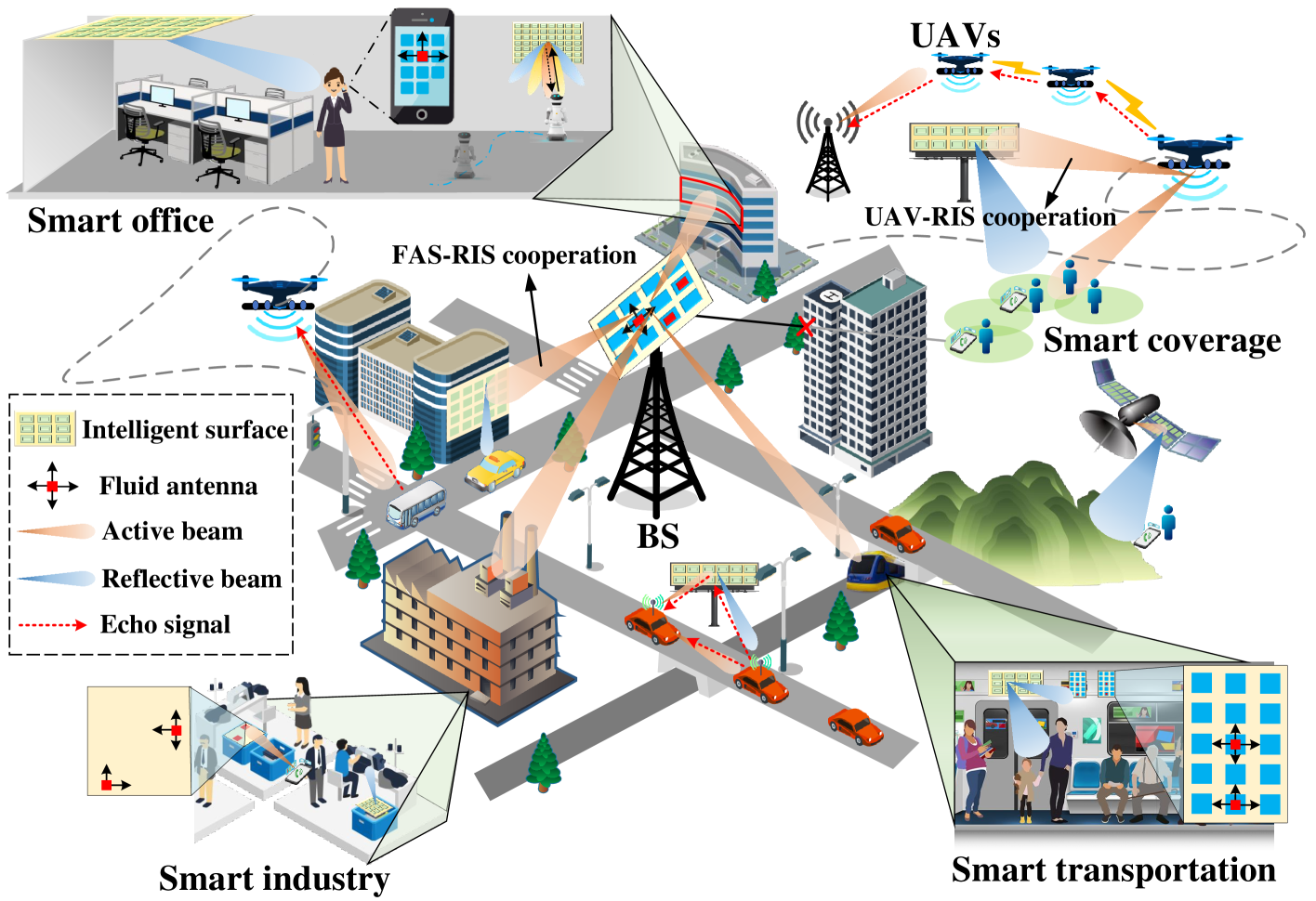
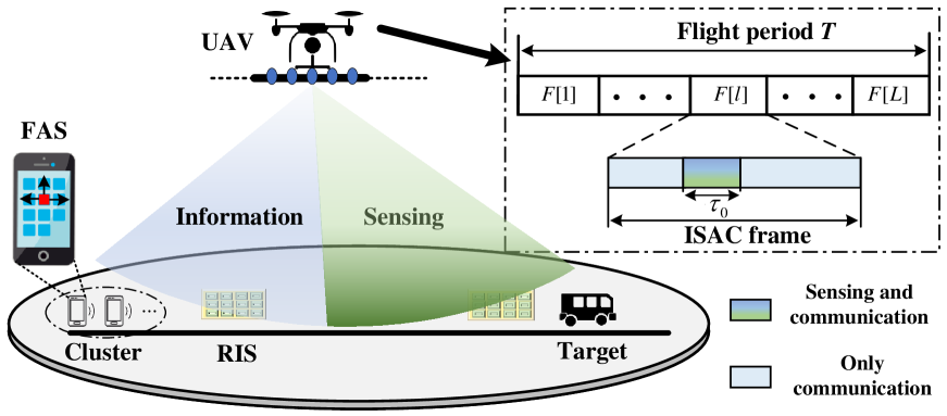
Figure 1: Illustration of Smart Environments for ISAC.

II-A Intelligent Surfaces

With the exploitation of myriads of low-cost reflecting/refracting elements, reconfigurable intelligent surfaces (RISs) [8] and stacked intelligent metasurfaces (SIMs) [9] can adaptively ameliorate the propagation channel between transmitters and receivers by beneficially designing their phase shifts and/or amplification. Intelligent surfaces can be placed in strategic locations to circumvent blocked line-of-sight (LoS) connections between transmitters and receivers, as shown in Fig. 1. Alongside this deployment strategy, intelligent surfaces can also be mounted onto mobile platforms, such as vehicles, drones, and even user terminals, providing a promising solution to enable these objects to modulate ambient signals as well as reflections, and actively assist their own localization and other services [8]. With a larger surface operating in a higher frequency band, RISs often implicate operation in the near field, where the spherical nature of the electromagnetic waves has to be considered. This in turn offers new opportunities to exploit precise spatial beam focusing both in angle and range, and to design bent beams for avoiding blockages [10]. These offer profound opportunities to improve the propagation environment.

II-B Unmanned Aerial Vehicles (UAVs) and Other Autonomous Platforms

For complementing conventional terrestrial cellular networks, BSs or relays may also be installed on unmanned aerial/ground/underwater vehicles to provide enhanced coverage, as shown in Fig. 1. By designing the placements/trajectories of these mobile BSs/relays on demand, the network topology can be dynamically adjusted in accordance with specific network requirements and services. For example, by exploiting the UAVs’ high mobility and strong air-ground LoS links, larger coverage, flexible observation position, and enhanced S&C performance can be achieved [6]. However, UAVs typically encounter challenges due to strict constraints on their size, weight, and power, which inevitably limit their capabilities. Additionally, stronger air-to-ground LoS links may cause severe interference. Besides these autonomous vehicles, high-altitude platforms (HAPs) are able to offer observation or communication services, typically powered with renewable sources and thus offering services with net-zero emissions. Moreover, thanks to the reduced launch cost and deployment time, low earth orbit (LEO) satellite systems offer promising opportunities for flexible global coverage.

II-C Flexible-Position FAS-aided Communications

In FAS [4], the positions of antennas at transmitters and/or receivers can be dynamically changed to obtain improved channel conditions, e.g., enhancing the channel gain and reducing the potential interference. A massive array of fluid antennas provides greater flexibility in designing beam width, avoiding undesirable side lobes, adjusting the frequency response of the array, and improving interference management. This is in contrast to traditional fixed-position antenna arrays, which suffer from reduced array gains due to inherent limitations in array geometry. Moreover, altering the positions of antennas could modify the Rayleigh distance [11], which sets the boundary between the far-field and near-field channels. While this further augments the near-field capabilities of RIS and the resultant propagation benefits, in practice, it is challenging to appropriately design the transmit beamforming vectors around the Rayleigh distance due to the dynamic antenna geometry. Moreover, existing far-field and near-field channel estimation schemes cannot be directly used for accurately estimating the "mixed"-field MIMO channel, which requires further investigation.

TABLE I: Illustration of several technologies roles in ISAC applications.
​​ Smart Propagation Engineering technology ​​​​​ Category Main functionalities Smart Propagation ​​ for ISAC ISAC for Smart Propagation ​​
Intelligent surfaces Adaptive channel Control for Improve channel DoF, low-cost/latency
(e.g., RIS, SIM) propagation channel enhance sensing diversity, channel estimation,
UAVs, HAPs Mobile BS/relay Management for higher spectral efficiency, blockage awareness
LEO satellite transmission topology interference suppression, channel control,
Fluid antenna Advanced antennas Transmitter/receiver S&C coordination gain, AI-aided predictive
Holographic MIMO antenna geometry multi-cell cooperation resource allocation
  • By smart propagation engineering technology, we refer to any hardware technology that has the ability to engineer the radio propagation channel.

II-D Cooperative Smart Environment Control

Effectively combining the above-mentioned techniques can proactively adapt to the wireless propagation environments. We categorize these smart technologies into three types based on their functions and objectives, as presented in Table I. These technologies may cooperate to efficiently manage the radio environment in terms of time, energy, and cost by leveraging their shared features and differences. Typically, UAVs work hand-in-hand with RISs to create virtual LoS channels for improving S&C coverage, as shown in the top-right corner of Fig. 1. Consequently, the channel gain improvement enabled by the exploitation of RISs can eliminate the need for UAVs to fly closer to users or targets, thereby reducing the UAV’s flight distance, power consumption and increasing its recharge interval. An example architecture was demonstrated in [12] where the authors proposed a UAV-aided RIS framework for maximizing the network throughput. On the other hand, FASs can adjust the antenna position according to the UAV trajectory and the RIS phase shifts, leading to more efficient exploitation of both random environmental scattering and controllable environmental reflection. In turn, RISs can be optimized concerning the antenna position for stronger signal power and for effective passive beam focusing.

Jointly optimizing the trajectory of mobile BSs, the phase shifts of RIS elements, and the position of FASs is extremely challenging due to the coupling of variables. However, it also presents new opportunities for fully unleashing the power of smart propagation engineering. It is noted that more resource cooperation provides improved flexibility to manage the radio environment, but it inevitably introduces more interactions amongst devices and more complex channel estimation processes. Therefore, when controlling the radio environment based on the near-instantaneous radio map, an intriguing question is how to effectively harness these three types of resources for collaborative propagation engineering at low computational complexity and low signaling overhead. Moreover, to provide efficient, reliable, and robust S&C services that meet the dynamic requirements of tasks, a cooperative smart propagation regime centered on users/targets remains an elusive challenge.

III Smart Propagation Engineering for ISAC

In this section, we discuss opportunities for exploiting smart technologies to provide enhanced ISAC services by improving the S&C channel gain, achieving augmented mutual assistance between S&C, and ultimately for designing cooperative ISAC networks.

III-A Improving S&C Performance via Enhancing the Channel Gain

To achieve enhanced S&C performance, a key challenge of ISAC assisted by smart propagation engineering is to simultaneously achieve the potentially conflicting channel control objectives of S&C. Specifically, cooperative radio environmental control necessitates the creation of high-rank channels associated with greater flexibility for data transmission, thereby achieving improved spatial resource allocation for enhancing the multiplexing gain, diversity gain, and interference nulling. By contrast, for sensing, typically only LoS links are useful, and non-LoS (NLoS) links are treated as unfavorable interference [7]. Thus, cooperative techniques should establish more LoS links for providing improved sensing coverage, more diverse observation angles, and richer target parameters. Propagation engineering offers key opportunities in fine-tuning the propagation channel for striking a balance between these conflicting S&C objectives of ISAC systems by optimizing the trajectory/placement of mobile transmitters/receivers, RIS phase shifts, FAS positions, etc. For instance, treated as both a mobile BS and a synthetic radar aperture, a UAV may optimize its trajectory to strike a balance between pathloss and channel gains for communication users, and observation diversity for targets. Moreover, to optimize the antenna position in FAS, smart propagation engineering may exploit channel paths to amplify the effective channel gains from the BS to all users. On the other hand, it additionally has to create larger antenna array apertures for capturing more echo signals from multiple directions, thereby improving the sensing performance attained.

III-B Enhanced Integration Gain Between S&C

An ISAC system can optimize its performance by strengthening the coupling between its S&C channels [13]. This facilitates more efficient exploitation of unified signals for S&C tasks. In the following, we outline how smart propagation engineering enhances the correlation of S&C channels. Firstly, considering that the S&C channel correlation is determined by the angular separations between users and targets, the trajectory of mobile BSs significantly impacts the resource allocation and waveform design of mobile ISAC systems. Thus it is essential to jointly design the transmit beamforming and trajectory to enhance the S&C performance [6]. Secondly, the S&C subspace of RISs having weak coupling may be rotated for improved coupling by adjusting the RIS phase shifts, hence striking improved S&C tradeoffs [13]. Thirdly, in FAS, the new DoF attained by antenna position optimization can be exploited for maximizing the S&C signal power over a desired direction and for simultaneously reducing the potential interference. Evidently, the collaborative resource design of UAVs, RISs, and FASs offers new opportunities for improving the S&C channel correlation. In particular, for operation in the near-field, achieving efficient cooperative control offers new opportunities for exploiting the channel correlation between users and targets not only in the angular domain but also in the distance domain [11].

III-C Smart Environment for Near-Field ISAC

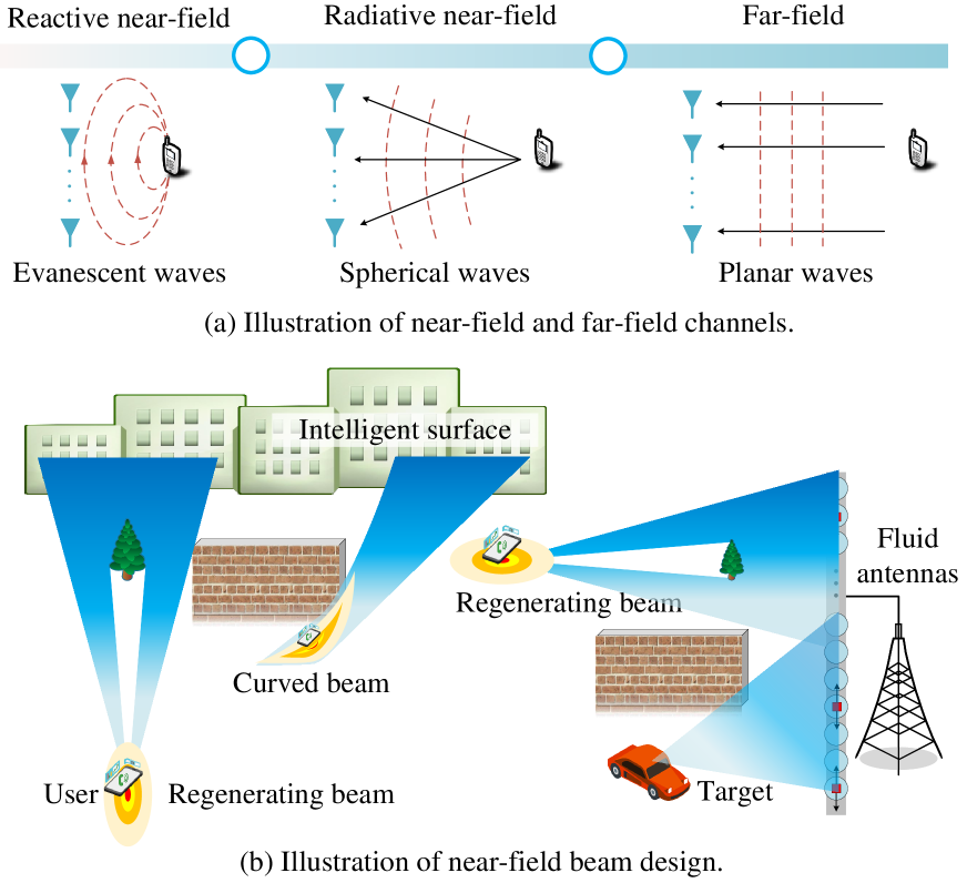
Again, the electromagnetic (EM) field radiated from antennas can be partitioned into near-field and far-field regions, where the EM waves in these regions exhibit different propagation properties, as shown in Fig. 2(a). Specifically, for targets/users near the antenna array, smart propagation engineering should consider spherical wave modeling, as the planar wave approximation is no longer valid. In contrast to far-field beamforming design, a transmitter array is designed to concentrate the beam at a specific location, termed as beamfocusing. This enables the formation of spot beams (beam power concentrated on a specific angle and range), allowing for simultaneous serving/detection of users/targets in the same direction, which is not easily accomplished in the far field. Importantly, due to potential blockages, different sets of clusters/users/targets may be visible from different portions of the antenna array or intelligent surfaces, as shown in Fig. 2(b). In this case, given the spherical wavefronts, the radiation from the unobstructed portion of the aperture can still converge to the desired focal point of beam focusing, as shown in Fig. 2(b). Furthermore, the near field may even permit the generation of curved beams that circumvent obstacles [10]. For instance, the self-regenerating properties of Bessel beams [10] restore the beam after encountering an obstacle with negligible reduction in radiation intensity. These properties facilitate the provision of robust S&C services in obstructed scenarios. In the near-field scenarios, variations of Doppler across these antennas offer new opportunities to estimate the radial and transverse velocities of targets, in turn also presenting new challenges to smart propagation engineering for ISAC systems.

Refer to caption
Figure 2: Illustration of ISAC for Near-field Smart Environments.

III-D Cooperative ISAC Networks

For network-level ISAC, inter-cell interference is a critical issue that limits the overall network performance. Interference suppression via smart propagation engineering is a promising technique of improving the S&C performance of ISAC networks, yet there is a paucity of related investigations in the literature. For instance, exploiting the UAV mobility combined with beamforming design effectively reduces the interference between BSs and UAVs. The RIS phase shift design should aim for reducing channel correlation between distinct users/targets and BSs, thereby mitigating multi-user/target interference [3]. FASs can exploit the potential diversity provided by the environment to avoid inter-cell S&C interference. In addition to coordinated interference management, the cooperative S&C benefits of ISAC networks is another promising paradigm. Specifically, by fully exploiting the potential of smart propagation engineering, a powerful combination of distributed/multistatic MIMO radar and coordinated multipoint transmission/reception can be supported. For instance, UAVs can serve as mobile transmitters/receivers to enhance S&C coordination. Furthermore, intelligent surfaces play a crucial role in establishing additional S&C channels, while FASs have the capability of dynamically adjusting the antenna geometry, for meeting near-instantaneous S&C requirements. However, designing a cooperative scheme for the smart environments of ISAC networks that effectively balances performance against complexity remains a challenging open issue hinging on sophisticated resource allocation.

At the network level of ISAC, conflicting metrics such as coverage and quality of service have to be balanced to meet the demanding overall network performance requirements. Specifically, if larger clusters of BSs work together to provide improved S&C services, the overall network spectrum efficiency will generally be reduced, since fewer users/targets can be served simultaneously. Furthermore, the challenge in designing and optimizing the resources of the ISAC network lies in judiciously balancing the various performance indicators, while taking into account both the channel fading and the unknown locations of targets/users. To tackle this issue, a useful approach is to apply stochastic geometry tools, which consider the random locations of BSs, users, and targets, along with random channel fading. This allows for modelling the relationships amongst various parameters and consequently facilitates more efficient optimization of the network resources, RIS/UAV positioning and FAS design.

IV ISAC for Smart Environments

In this section, we explore the ISAC-benefits of smart propagation engineering, including cooperative engineering, low-overhead control, predictive resource allocation, and blockage awareness.

IV-A ISAC for Cooperative Smart Environment

Harnessing numerous UAVs, RISs, and FASs for effective cooperation is a promising option for improving the S&C performance and for reducing the time/energy consumption, but it also poses challenges related to the essential information exchange across systems. To tackle this issue, the S&C functionalities of ISAC systems can be exploited to facilitate the collaboration of the various system components. For instance, based on the dynamics of targets and users, it is conducive to combine sensing results and dispatch request messages for collaboration based on the fusion of sensory data [2]. This enables these systems to operate in dynamic clusters, identifying potent cooperation that maximizes gains, while avoiding deficient cooperation having only incremental gains. Moreover, incorporating sensory data, such as the positions of users and targets, can prevent unnecessary control procedures. For example, if the channel fluctuation in a particular area drops below a certain threshold, the resource allocations do not have to be updated. It is worth noting that ISAC is capable of managing radio propagation across various geographical scales. Since the UAV movement is of limited speed, it is more suitable for propagation engineering in scenarios of more relaxed latency requirements. Intelligent surface technology by contrast allows for near-real-time applications, but over a limited area. With the use of an FAS, the antenna position can be adjusted based on the channel status and user mobility characteristics.

IV-B ISAC for Low Overhead Control

Resource optimization in smart UAV, RIS, and FAS aided scenarios relies heavily on the channel state information (CSI) as well as on the locations of users and targets. Estimating the CSI becomes complex as the number of nodes plus active and passive antennas increases, especially when these systems collaborate with each other. Therefore, sensing-assisted CSI estimation in ISAC systems shows great potential to reduce training overhead [8, 14]. By representing CSI in terms of path-delay and angle in fewer dimensions, we can significantly reduce the CSI estimation overhead. Employing sensing for improved beam steering may even circumvent CSI acquisition altogether by exploiting the direction finding capabilities of radar to inform the BS of the user’s direction for high-gain beam focusing. In [8], an ISAC framework using vehicle-mounted intelligent surfaces was conceived for strategically directing the echo signals towards the sensing receivers. By exploiting the high-accuracy sensing results, the signaling overhead of the RIS phase shift design may be effectively reduced. Moreover, the uplink data transmission of communication users may also be harnessed for gathering information on the environmental and target status for smart propagation engineering.

Different smart propagation engineering technologies achieve low-overhead control in unique ways. For instance, incorporating sensors into the RIS enhances its capability of analyzing echo signals. Hence, the sensing results support self-adaptive passive beamforming design, without necessitating any control signals from the BS. Sensing harnessed for user discovery may also reduce the UAV-user interaction, facilitating real-time trajectory design. Furthermore, environment-related sensing results (e.g., locations of scatterers) facilitate seamless FAS adaptation, without requiring CSI estimation. Additionally, the sensing results can be used for constructing a 3D map of the environment, including both dynamic and quasi-static information. This map enables the modeling of wave propagation through ray-tracing techniques, thereby reducing the need for environmental control and ultimately the overhead. Apart from facilitating smart propagation engineering in a single cell, ISAC can also reduce the corresponding time/power consumption of handovers between, for example, UAV-mounted BSs and terrestrial BSs, and thus conserve time and power resources.

Refer to caption
Figure 3: Illustration of ISAC for smart environments.

IV-C Predictive Resource Allocation for Smart Environments

Based on the estimated user and target dynamics as well as service requirements of S&C, predictive resource allocation for UAV, RIS, and FAS can reduce service delays and improve reliability. However, it is challenging to jointly optimize the resource allocation of multiple nodes due to the coupled variables. A possible solution is to actively/passively track the state of the served/detected users/targets only individually [8]. The system can then combine local sensor data and predict the trajectories of the corresponding users/targets, as shown in Fig. 3. By jointly optimizing the network’s resource allocation and user/target scheduling together with the smart environment, high-quality S&C services can be achieved. In addition to predictive design based on sensing results, more efficient resource allocation can be supported based on predicting demands for data transmission services.

IV-D Blockage Awareness for Channel Control

While the above potential performance enhancements are promising, they erode due to potential blockages. Hence, blockage awareness through sensing is beneficial for reliable and robust S&C services in dense obstruction scenarios. According to the estimated movement of users/targets, the UAV location can be optimized based on accurate environmental information to avoid blockages and reduce propagation losses. For near-field S&C, the antenna or surface array may be partially blocked [10], as shown in Fig. 2(b). In other words, the energy of each user/target is focused on a particular section of the array, as different regions of the array may observe different users. Furthermore, large targets themselves may cause potential blockages, and thus the propagation engineering should be designed by giving cognizance to blockages. In turn, blockages can be exploited for significantly reducing interference between users and cells. As a result, environmental awareness through ISAC offers a breakthrough capability for controlling propagation based on user locations to avoid outages.

V Case study: Propagation Engineering for ISAC

Refer to caption
Figure 4: Illustration of simulation scenarios.
Refer to caption
Figure 5: Rate improvement by smart propagation engineering.

To demonstrate the efficiency of propagation engineering for ISAC, we consider the optimization of communication performance under sensing performance constraints. As shown in Fig. 4, we jointly optimize the resources of a UAV, a RIS, and several users supported by a FAS. Fig. 5 characterizes various propagation engineering designs and their achievable rates under different sensing performance constraints. The UAV’s maximum horizontal flight speed is set as 30 m/s with a flight altitude of 30 m. Additionally, the noise power at the user and the UAV are set to -70 dBm and -90 dBm, respectively, and the maximum transmit power is 1 W.

Observe from Fig. 5 that collaborative smart propagation engineering using all three techniques significantly enhances the rate attained, compared to the unassisted scenarios. However, as the sensing echo signal-to-noise ratio (SNR) increases, the achievable rate of the communication schemes relying on the assistance of smart propagation engineering decreases rapidly. The primary reason is that smart propagation engineering systems tend to dedicate more resources to the sensing task due to the high sensing SNR required at the cost of communication performance erosion. When the sensing SNR requirement exceeds a certain value, it becomes impractical to achieve satisfactory sensing performance without the assistance of smart propagation engineering. By contrast, the schemes relying on UAV systems can extend the region of adequate sensing performance, while significantly improving communication performance, especially for lower sensing demand. This is because accurate UAV trajectory design significantly reduces the pathloss by performing S&C tasks closer to targets and users.

VI Open Problems

The horizon for research and innovation in both smart propagation engineering and ISAC technologies is wide open. Some of these are discussed as follows.

VI-A AI assisted Smart Environment for ISAC

Artificial Intelligence (AI)-based approaches offer a promising solution for the scenarios of hostile wireless channels and user mobility, eliminating the need for time-consuming iterations routinely harnessed in traditional algorithms [15]. AI facilitates the real-time adaptation of smart environments by predicting future network states using the recent propagation data gathered. Furthermore, the complexity of the holistic smart environment design across UAV trajectories, RIS phase shifts, and FAS positioning, may be reduced by AI solutions upon evaluating only a fraction of the combined search-space. The sensing functionality of ISAC in turn has a lot to offer for harnessing intelligence in the face of uncertainty. Real-time data gathering by sensing throughout every transmission is the only way to create native network intelligence. Finally, federated learning (FL) provides a promising solution for privacy-preserving distributed training. One could envisage each smart system updating its local AI model based on ISAC data and sending the parameters to a central server for global AI model update in a FL manner. This requires a bespoke training algorithm for the ISAC process, which deserves further investigation.

VI-B Smart Environments for Secure ISAC

ISAC comes with its own unique security challenges due to the shared use of spectrum and the broadcast nature of wireless transmission. While smart propagation engineering strikes a flexible balance in simultaneously achieving secure S&C, the high complexity of obtaining the locations and channels of potential eavesdroppers makes securing ISAC services particularly challenging. Furthermore, sensing imposes vulnerability on the network, since an unauthorized sensing receiver may eavesdrop on the target’s location information, or may illegitimately acquire situational awareness. Unlike communication security, which can be designed at the data level to prevent eavesdroppers from obtaining information, sensing security can only be designed at the physical layer. Therefore, how to adapt smart environments to facilitate S&C security is an issue worth studying.

VI-C Smart Environments for Vehicular ISAC Cooperation

For highly dynamic vehicular networks, developing a general solution for smart propagation engineering has substantial challenges. Considering that vehicles on the same road often have similar mobility characteristics, particularly for platoons travelling in a specific formation, it is advantageous to exploit these similarities for minimizing control overhead by designing vehicular cooperation schemes. Smart environments can help vehicles collaboratively obtain information in a wider field of view, thereby providing more comprehensive situational awareness for transportation. By contrast, the sensing results obtained by vehicular onboard sensors can be used for efficient control of smart environments.

VII Conclusions

Integrating multiple smart propagation engineering techniques with ISAC presents significant design challenges, but also compelling opportunities. We have discussed new design considerations and highlighted essential challenges for the joint design of smart environments and ISAC, revealing their mutual benefits. We further showcased the benefits of these concepts through an ISAC case study. Given the relatively uncharted territory of ISAC empowered by smart propagation engineering, this article endeavored to inspire future research in this field.

References

  • [1] J. A. Zhang et al., “An overview of signal processing techniques for joint communication and radar sensing,” IEEE J. Sel. Top. Signal Process., vol. 15, no. 6, pp. 1295–1315, Nov. 2021.
  • [2] F. Liu et al., “Integrated sensing and communications: Toward dual-functional wireless networks for 6G and beyond,” IEEE J. Sel. Areas Commun., vol. 40, no. 6, pp. 1728–1767, Jun. 2022.
  • [3] M. A. ElMossallamy et al., “Reconfigurable intelligent surfaces for wireless communications: Principles, challenges, and opportunities,” IEEE Trans. on Cogn. Commun. Netw., vol. 6, no. 3, pp. 990–1002, Sep. 2020.
  • [4] K.-K. Wong, A. Shojaeifard, K.-F. Tong, and Y. Zhang, “Fluid antenna systems,” IEEE Trans. Wireless Commun., vol. 20, no. 3, pp. 1950–1962, Mar. 2021.
  • [5] C. Huang et al., “Holographic MIMO surfaces for 6G wireless networks: Opportunities, challenges, and trends,” IEEE Wireless Commun., vol. 27, no. 5, pp. 118–125, 2020.
  • [6] K. Meng et al., “Throughput maximization for UAV-enabled integrated periodic sensing and communication,” IEEE Trans. Wireless Commun., vol. 22, no. 1, pp. 671–687, Jan. 2023.
  • [7] R. Liu, M. Li, H. Luo, Q. Liu, and A. L. Swindlehurst, “Integrated sensing and communication with reconfigurable intelligent surfaces: Opportunities, applications, and future directions,” IEEE Wireless Commun., vol. 30, no. 1, pp. 50–57, Feb. 2023.
  • [8] K. Meng et al., “Sensing-assisted communication in vehicular networks with intelligent surface,” IEEE Trans. Veh. Commun., pp. 1–17, 2023.
  • [9] J. An et al., “Stacked intelligent metasurfaces for efficient holographic MIMO communications in 6G,” IEEE J. Sel. Areas Commun., vol. 41, no. 8, pp. 2380–2396, 2023.
  • [10] A. Singh et al., “Wavefront engineering: Realizing efficient TeraHertz band communications in 6G and beyond,” arXiv preprint arXiv:2305.12636, 2023.
  • [11] M. Cui, Z. Wu, Y. Lu, X. Wei, and L. Dai, “Near-field MIMO communications for 6G: Fundamentals, challenges, potentials, and future directions,” IEEE Commun. Mag., vol. 61, no. 1, pp. 40–46, 2023.
  • [12] M.-H. T. Nguyen, E. Garcia-Palacios, T. Do-Duy, O. A. Dobre, and T. Q. Duong, “UAV-aided aerial reconfigurable intelligent surface communications with massive MIMO system,” IEEE Trans. Cogn. Commun. Netw., vol. 8, no. 4, pp. 1828–1838, 2022.
  • [13] S. P. Chepuri, N. Shlezinger, F. Liu, G. C. Alexandropoulos, S. Buzzi, and Y. C. Eldar, “Integrated sensing and communications with reconfigurable intelligent surfaces,” arXiv preprint arXiv:2211.01003, 2022.
  • [14] S. Mura, M. Mizmizi, U. Spagnolini, and A. Petropulu, “Enhanced channel estimation in mm-wave MIMO systems leveraging integrated communication and sensing,” in IEEE International Conference on Acoustics, Speech and Signal Processing (ICASSP), Seoul, Korea, 2024.
  • [15] S. Evmorfos, A. P. Petropulu, and H. V. Poor, “Actor-critic methods for IRS design in correlated channel environments: A closer look into the neural tangent kernel of the critic,” IEEE Trans. Signal Process., vol. 71, pp. 4029–4044, 2023.

Turkish UCAV Akıncı test fires Roketsan ÇAKIR cruise missile


Türkiye Tests ÇAKIR cruise missile fired from AKINCI TİHA. 

Çakir is a modern cruise missile developed by Turkey's defense industry and was recently test-fired from the Akinci Tiha (Turkish: Bayraktar Akinci Tactical UAV), a large drone designed and produced by the country's leading drone manufacturer Baykar. 

The successful test-firing of the Çakir missile from the Akinci Tiha is a significant milestone for Turkey's defense industry, as it demonstrates the country's capability to produce advanced unmanned aerial systems (UAS) and precision-guided munitions. 

The Akinci Tiha is a high-altitude, long-endurance drone capable of conducting a wide range of missions, including intelligence, surveillance, and reconnaissance (ISR), target acquisition, and strike missions. It has a maximum takeoff weight of 5,500 kg, a wingspan of 20 meters, and a range of up to 6,000 kilometers.

Baykar’s UAV integrated with domestic missile - Türkiye News


Baykar’s UAV integrated with domestic missile

ANKARA

Baykar’s UAV integrated with domestic missile

Akıncı, the armed unmanned aerial vehicle developed by Turkish defense company Baykar, has achieved a precise hit on a target at sea from a distance of 100 kilometers in a test launch using the domestically developed Çakır cruise missile.

As part of the Bayraktar Akıncı Project under the leadership of the Presidency of Defense Industries, integration efforts for new ammunition and systems continue, with a new landmark achieved with the integration of the Çakır cruise missile.

The unmanned aerial vehicle conducted another test with the missile developed nationally by Roketsan at the Akıncı Flight Training and Test Center in the northwestern province of Tekirdağ’s Çorlu district.

Taking off with the Çakır missile, Bayraktar Akıncı flew to the northern province of Sinop for a long-range firing test. Fired from the unmanned aerial vehicle at the Sinop firing range from a distance of 100 kilometers, the Çakır cruise missile hit the target over the Black Sea at a speed of 800 km/h with precise accuracy.

The Bayraktar Akıncı UAV, which entered the inventory of Azerbaijan, had its first flight on Feb. 9, witnessed by Azerbaijani President İlham Aliyev and Baykar Chairman Selçuk Bayraktar. The export and cooperation agreement with Saudi Arabia in 2023 became the largest single export agreement in the history of the Turkish defense and aerospace industry.

Turkish UCAV Akıncı fires Roketsan cruise missile in global 1st | Daily Sabah


The Turkish defense industry giant Roketsan-made Çakır cruise missile was successfully fired from the state-of-the-art unmanned combat aerial vehicle (UCAV) Akıncı.

A Çakır cruise missile is seen deployed under the Akıncı UCAV
before being fired in an undisclosed location, May 11, 2023.
(Courtesy of SSB)

The Çakır was deployed at an altitude of 7,000 meters, marking its inaugural flight with the indigenous turbojet engine KALE KTJ-1750.

Ismail Demir, head of the Presidency of Defense Industries (SSB) shared the images of the test-firing of the Çakır missile on his social media account.

“For the first time in the world, a cruise missile was fired from a UCAV,” he wrote.

Demir said that the missile was fired with an engine whose critical components were domestic and hit the target with pinpoint accuracy, congratulating the local defense industry.

The Çakır cruise missile is a cutting-edge weapon system designed to enhance the capabilities of the armed forces across various platforms including land, sea and air.

Leveraging state-of-the-art features and an effective warhead, the Çakır cruise missile empowers Roketsan to shape the battlefield with innovative technologies.

This versatile missile can be launched from a range of platforms such as fixed-wing and rotary-wing aircraft, UCAVs, armed unmanned sea vehicles (AUSVs), tactical wheeled land vehicles and surface platforms.

Its operational flexibility equips users with an array of options to engage both land and sea targets effectively.

With a range exceeding 150 kilometers (90 miles), the Çakır cruise missile enables precise strikes against surface targets, land and shoreline targets, strategic land installations, expansive areas, and even fortified caves.

With its advanced intermediate stage and terminal guidance systems, Çakır is able to engage its targets with high precision in all weather. Thanks to the network-based data link, it also allows target change and task cancellation depending on user selection while advancing to the target.

Next-Level Arsenal for Akinci: Unmanned Aircraft Vehicle Successfully Launches Cakir Cruise Missile | Defense Express


Turkish unmanned aerial vehicle Akinci successfully launched the Çakır cruise missile, equipped with the domestic turbojet engine KTJ-1750 from Kale Arge, developed by Roketsan. The Chairman of the Presidency of Defence Industries of the Republic of Turkey (Savunma Sanayii Başkanlığı, SSB), Ismail Demir, shared the news on his Twitter account.

"All critical components of Çakır, released from AKINCI TIHA, were propelled by a domestic engine and hit the target with high precision," the statement said.

Defense Express, Next-Level Arsenal for Akinci, Unmanned Aircraft Vehicle Successfully Launches Çakır Cruise Missile
Çakir cruise misilles / Photo credit: MilliTeknolojiHamlesi

Çakır missile is a state-of-the-art Turkish development, first introduced in 2022. It is designed to engage ground and surface targets. The missile can fly close to the water surface, has terrain-following capability, and features the option to update its route, change targets, or abort the mission during flight. It can also maneuver as required.

Defense Express, Next-Level Arsenal for Akinci, Unmanned Aircraft Vehicle Successfully Launches Çakır Cruise Missile
Çakir cruise missile launch / Illustrative photo by Roketsan

The tactical and technical specifications of this missile are as follows: length - 3.3 m, total weight - 275 kg, with a warhead weighing 70 kg. It has a range of 150 km, a cruise speed of 0.75-0.85 Mach, and can be equipped with fragmentation, thermobaric, or armor-piercing warheads.

It's worth noting that this is the second cruise missile associated with Akinci unmanned aerial vehicle that has made headlines recently. Previously, we reported on the official demonstration of the mini cruise missile Kemankes by the Turkish Company Baykar, designed for integration with Bayraktar series UAVs, including TB2, TB3, and Akinci.

This cruise missile is capable of engaging targets up to 200 km away, and weighs 35 kg, with a warhead weighing 6 kg. The first missile launch is expected within 1-2 months, and serial production is planned to commence by the end of this year.


Friday, March 1, 2024

Chinese Navy Liaoning aircraft carrier returns to sea with J-15 and J-35 jet mockups


Chinese Navy Liaoning aircraft carrier returns to sea with J-15 and J-35 jet mockups


As reported by Caiyunxiangjiang Louis Cheung on February 29, 2024, a new video has provided a clearer perspective on the J-35 mockup situated on the deck of the Liaoning aircraft carrier, suggesting that the vessel, after its return to sea, is undergoing deck-handling trials. This development is pivotal, as it suggests a shift from previous plans which anticipated the deployment of the J-35 on China’s forthcoming generation of carriers, specifically designed with catapult systems as opposed to the existing ski-jump ramps.


Russian Vyborg Shipyard laid the Purga ice class coastguard ship of project 23550 925 001 

The Liaoning aircraft carrier of the Chinese Navy is back at sea
with mockups of J-15 and J-35 jets. (Picture source: Caiyunxiangjiang)


Additionally, the imagery showcases a mockup of the J-15 fighter alongside the J-35 on the Liaoning. The J-15, a regular component of China's operational aircraft carrier groups, particularly on the Liaoning and Shandong, appears to be undergoing evaluation for compatibility and training purposes in conjunction with the J-35. The presence of the J-15 mockup, potentially hinting at a new variant of the aircraft, is indicated by the unique shape of the cockpit area, which is visible beneath its protective covering.


The J-15, known in NATO terminology as Flanker-X2 and also referred to as the Flying Shark, is China's primary carrier-based aircraft. Originating from the design framework of the Russian Su-33, it incorporates two Shenyang WS-10A engines, achieving a maximum speed of 2,410 km/h and maintaining operational range capabilities up to 3,500 km. Despite its advanced design, the J-15's operational efficacy is partially restricted by the Liaoning's ski-jump launch mechanism, impacting its fuel consumption and thereby influencing its payload capacity and maximum takeoff weight.

Andreas Rupprecht, a noted observer of Chinese aerospace developments, has discussed the potential use of the J-15 mockups for the development of an electronic warfare variant, speculated to be designated as the J-15D. This variant would represent a significant step towards enhancing the electronic warfare capabilities of the People's Liberation Army Navy (PLAN), mirroring the functionalities of comparable systems like the U.S. Navy’s EA-18G Growler.

The employment of aircraft mockups is a recognized practice in naval operations for facilitating the training of deck-handling procedures, including the operation of aircraft elevators and the management of space on the flight deck and in hangar areas. Such practices contribute to the operational readiness and efficiency of aircraft carrier crews.

Recent activities involving the Liaoning, including the integration and testing of the J-35 and potential J-15D variants, signal a progression towards more advanced maritime operations. This also indicates a continued development of the capabilities of China’s current carrier fleet, which operates primarily with Short Take-Off But Arrested Recovery (STOBAR) systems, in contrast to the future catapult-assisted takeoff but arrested recovery (CATOBAR) systems planned for new carriers.

The J-35, specifically designed for carrier operations, while limited by the ski-jump ramp system, is expected to offer new operational capabilities. Designed for single-pilot operations, the aircraft is tailored for carrier compatibility and aerodynamic efficiency, featuring specifications that support its role in varied mission scenarios. The aircraft's design facilitates a balance between maneuverability and operational range, complemented by an array of advanced onboard avionic systems.

The unfolding scenario surrounding the J-35 and the upgraded J-15 variants on Chinese aircraft carriers reflects the country's ongoing efforts to expand and refine its naval air power capabilities. These advancements are indicative of China's broader military modernization efforts, aiming to enhance the operational scope and strategic depth of its naval forces. The Liaoning’s transition from a training to a combat platform, along with its adaptations for increased aircraft carriage and defensive capabilities, underlines the strategic evolution of China's naval ambitions and its engagement in expanding its maritime operational readiness.


Fresh sightings of J-35 progress on deck of China’s Liaoning aircraft carrier


Photos have been posted online of an apparent full-scale dummy of China’s new fifth-generation fighter on one of the country’s aircraft carriers.

The images began circulating on Weibo last week and appear to be of a model of a J-35 stealth fighter on the Liaoning, China’s first aircraft carrier.

Then on Monday state-owned, Hong Kong-based newspaper Wen Wei Pao published clearer pictures of the dummy wrapped in a tarpaulin on the carrier at a shipyard on the northeast coast owned by Dalian Shipbuilding Industry Company.

Photos of what appears to be a full-scale model of a J-35 on the deck of the Liaoning have surfaced on Chinese social media. Photo: Weibo

The J-35 is being developed by Shenyang Aircraft Corporation as China’s second fifth-generation fighter jet, following the J-20.

The jet is designed for use on aircraft carriers and is still in the development and prototype phase but it is touted as the Chinese equivalent of Lockheed Martin’s fifth-generation fighter jet, the F-35.

Collin Koh, a senior fellow at the S. Rajaratnam School of International Studies in Singapore, said the dummy of the J-35 could serve various purposes.

“One most straightforward assessment is that the Liaoning, which has long been designated as a test bed for PLA carrier capabilities, is conducting experiments on the J-35 as a viable carrier-borne fighter jet,” Koh said.

He said the dummy could also be for “signalling purposes”.

China at a Glance Newsletter

Your daily must-read of essential stories from China, including politics, economy and current affairs.

By submitting, you consent to receiving marketing emails from SCMP. If you don't want these, tick here

“The Chinese are possibly aware they’re being watched with interest by external parties so the mock-up is put out there in open view to send a veritable signal, possibly to the US,” Koh said.

A model of next-generation jet was on show at the World Defence Show in the Saudi capital Riyadh earlier this month. Photo: AFP

A scale model of the J-35 was first unveiled at the Zhuhai Airshow in 2012 and observers say the most recent images indicate the jets could soon be in operation.

Once handed over to the People’s Liberation Army, the J-35 is likely to be mixed and matched with the fourth-generation J-15 already on the Liaoning and Shandong, China’s second carrier.

The J-35s will also reportedly be stationed on the Fujian, the country’s newest aircraft carrier, which is undergoing sea trials and expected to be in service by 2025.

Unlike its two predecessors, which used ski-jump take-off ramps, the Fujian has an electromagnetic catapult system that allows planes to be launched more frequently and with more fuel and munitions.

Yue Gang, a retired PLA colonel, said it was feasible to deploy the J-35 on all three Chinese carriers.

But the fighter’s guidance systems and maintenance facilities would have to be adapted for the Liaoning, the carrier that was commissioned over a decade ago.

“If the deployment test on Liaoning is successful ... the same deployment will be implemented on the Shandong and Fujian ships as soon as possible,” he said, adding that similar developments in Japan and the US had prompted China to speed up.

China airs footage of Fujian aircraft carrier featuring advanced catapult launch system

But having J-35s on carriers of different launch types could be challenging, according to Yoon Suk-joon, a visiting research fellow at the Korea Institute for Military Affairs and specialist in Chinese weapons systems.

“There is a significant technical and operational difference between the [ski jump ramps] and the [electromagnetic catapult] method,” Yoon said.

“This means that even if the J-35 type is mounted on the Fujian for sea trials, training is required for the carrier-based aircraft pilots already on the Liaoning and Shandong.

“There is a big difference between doing this on an actual aircraft carrier than on the ground.”

China has been promoting its new stealth fighters abroad in an attempt to present its aircraft as a choice for countries without access to US and European fifth-generation jets.

Chinese state-owned firms showcased a model of a J-35 – also known as the FC-31 – at the World Defence Show in Riyadh, Saudi Arabia, earlier this month. It was also featured in the International Defence Exhibition and Conference in Abu Dhabi last year.

Last month, Pakistani Air Chief Marshal Zaheer Ahmed Baber Sidhu announced that his country planned to buy the jets as part of plans to modernise its air force, but did not give further details of the procurement.

Koh said that he was not aware of potential buyers other than Pakistan.

“Still, the J-35 would serve as a potential alternative buy among a host of offerings worldwide, and depending on the client’s financing ability and mission requirements, as well as political considerations,” Koh said.

“But for now, one can only say the J-35 has potential, especially among the less-endowed air arms around the world, in particular in the developing world.”

Light's Topology Shrugs Off Turbulence

Scientists Transmit Data via Magnetic Skyrmions in Laser Beams with 98% Fidelity Over Hundreds of Meters A laser beam scrambled beyond rec...