Major
progress in robotics and microelectronics, as well as significant
advances in nanoelectronics, make it possible to efficiently explore
both near Earth and deep space with small spacecraft1.
These spacecraft and ultra-small satellites, sometimes referred to as
Cubesats, are poised to permanently transform the global economy and
mankind’s approach to space exploration. In particular, small spacecraft
have dramatically lowered the initial capital cost of deploying
on-orbit capability. Historically, only large companies and government
organizations could meet the cost (>$100M USD) of manufacturing a
functional space asset, purchasing the launch, and acquiring insurance.
Small satellites, enabled by the miniaturization of electronics and
related systems, have brought the entry capital barrier down to as low
as $1M USD. This has allowed new players, such as universities and small
companies, to acquire custom on-orbit assets. Launch providers have
added fuel to this fire with the introduction of numerous, low-cost
secondary payload rides.
Small satellites and Cubesats, as well as
their related capability have touched all aspects of human activity.
Private investors have embraced the use of the small surveillance
platforms to monitor natural resources and commerce activity. These
companies include Terra Bella (formerly Google Skybox) and Planet. In
response to the growing demand for small satellite technology, a variety
of small businesses has appeared to support the component needs of
satellites suppliers. Cubesats exist already on almost every University
campus and span the spectrum from large research institutions such as
the Georgia Institute of Technology to small community colleges, e.g.,
Medger Evers College. A plethora of organizations associated with
defense and surveillance actively use small satellite assets to conduct
their intelligence missions. The Air Force continues to build the
skilled workforce through sponsorship of University Nanosat Program.
Civil space organizations have focused multiple programs and
solicitations on Smallsat technology development as well as on
leveraging small satellite platforms to perform unique science missions.
Multiple NASA centers develop and deploy small satellites and Cubesats
from the International Space Station. Box 1
shows the growth in the number of publications related to satellites
and relevant systems, reflecting a strong increase in interest in this
field.
While small satellites have enjoyed initial success, the
civil sector requires more sophisticated spacecraft to perform remote
Earth sensing, precision agriculture, monitoring erosion and sea
pollution, precision weather prediction, navigation, global
satellite-based communication systems, and many other tasks that could
provide a considerable boost to the efficacy of these areas of human
activity2.
Moreover, smart robotic orbiters and landers could efficiently explore
other planets including Venus and Mars. Apparently, the next steps in
the use of small satellites and Cubesats to perform civil space missions
could be divided into two categories, (i) exploring our solar system
and beyond, and (ii) leveraging the near-Earth space. Missions in our
solar system include further exploration of the Moon3, exploration of Mars4,5, and sending long-life probes to planets, comets, asteroids6, and deep space7. In parallel, intense use of near-Earth space will continue to benefit the entire mankind—from
using small space assets for advanced communication, global internet
access, precise weather prediction, asteroid tracking, global
positioning systems, to near-Earth space exploration (e.g., registration
of radiation and corpuscular fluxes, and their effect on communication
systems and weather)8,9. These missions demand very sophisticated, autonomous equipment that reliably operates within the hostile space environment—very
low and high temperatures, extreme radiation, impact by high-speed dust
particles, and other severe conditions. In this review, we provide a
brief literature survey on the unique features of nanostructured
materials in the context of their application in electric propulsion
(EP) systems and thrusters, with a strong focus on Hall-effect and
gridded ion thrusters. In particular, the application of vertically
aligned nanotube patterns, nanotube- and graphene-based nanomaterials,
as well as complex metamaterials involving nanoscaled structures and
related physical effects are discussed. Moreover, the concepts of
adaptive and self-healing thrusters are proposed, presenting systems
capable of self-adjusting the operation mode. Development of a new
generation of miniaturized EP platforms is expected, based on the
ingression of nanomaterials into space technology.
Electric propulsion systems as the first choice
Wide
application of nanoapproach in space technology could be a possible way
to realize smart, nanoscale spacecraft. According to the NASA’s 2015
Nanotechnology Roadmap Initiative, nanomaterials and related techniques
should constitute a base for the new generation of spacecraft10. Evidently, EP systems are the primary candidates for driving the development of these novel spacecrafts—see Boxes 2 and 3
to learn more about design and impressive benefits of the EP platforms
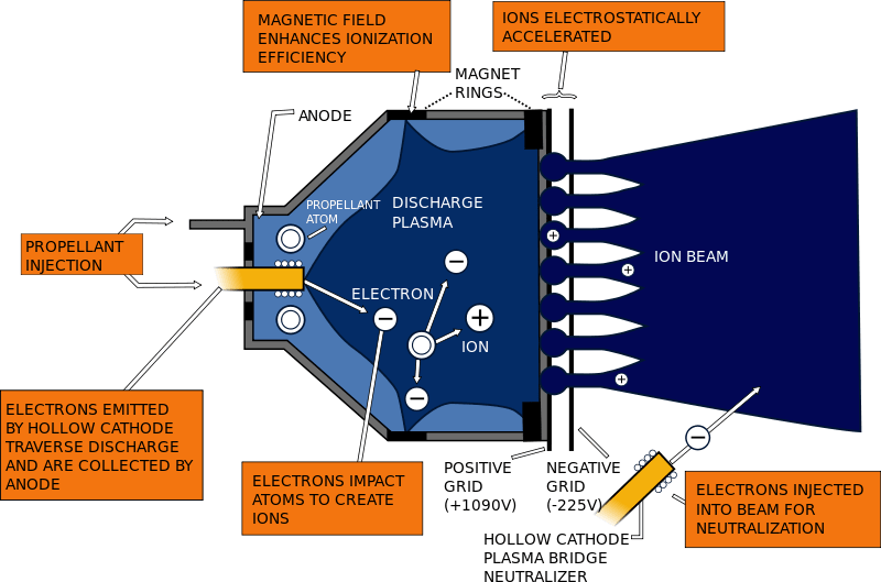
and the two most advanced types of EP devices, namely Hall-type and
gridded ion thrusters.
Why is EP unique? Powerful liquid and solid
propellant rocket engines are commonly used during the first stages of
space flight. Despite relatively low specific impulse11
(i.e., propellant exhaust velocity), they feature very high
thrust-to-weight ratios. Thus, they are most suitable for launch
applications and reaching orbital velocity. In contrast, most
long-duration missions imply low thrust but require high specific
impulse to efficiently control the orientation and location of the
spacecraft. Unfortunately, small chemical rocket engines deliver very
low specific impulse at low thrust levels. In contrast, the EP that uses
electrical energy to accelerate ionized propellant and delivers very
high specific impulse is the leading propulsion solution for
long-duration missions12.
EP devices employ electrostatic or electromagnetic forces to accelerate
the propellant and thus do not have physical limitations on their
exhaust velocity.
In terms of specific impulse (which shows how
efficiently the propellant is used), this means that EP can develop
thrust at a very low propellant mass flow rate, i.e., the mass of
propellant required for the entire mission could be small. Such a system
is the best candidate for long-duration spacecraft control13.
Thrusters employing electrostatic methods of acceleration (specifically
Hall- and gridded ion-type devices) are superior to other electric
types due to low secondary losses of energy (e.g., for ionization of
propellant and heating), and they are the most promising platforms for
deep space and interplanetary flights. Other devices such as pulsed
plasma thrusters14,
magnetoplasmadynamic thrusters, and novel perspective approaches, e.g.,
the variable specific impulse magnetoplasma rocket (VASIMIR15,
are also suitable for specific space tasks). It is important to
remember that because EP devices use electrical power to accelerate the
propellant, their operation is power limited.
The general aim of
this review article is to demonstrate encouraging examples and possible
approaches for boosting the performance and lifespan of spacecraft EP
systems by the wide-and-wise application of nanoscaled materials and
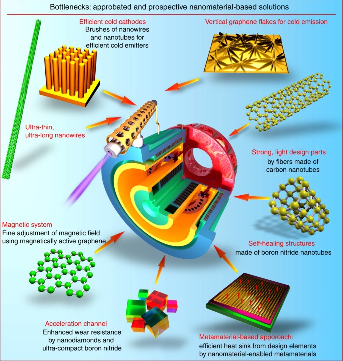
techniques in the most challenging, critical areas (see Fig. 1
for the most determined “bottlenecks” to be possibly resolved with the
use of the next-generation nanomaterials and metamaterial systems).
Eventually, we try to set the major directions and approaches for
self-healing thruster platforms suitable for the ultra-long deep space
missions.
Hall-type and ion thrusters as the two main candidates
Hall-type
and gridded ion thrusters are among the most advanced, mature EP
technologies with space-proven, relatively long flight heritage; some
prominent EP-driven missions are described in more detail below.
Specifically, a Hall-type thruster is a device that uses the closed
electron drift, so-called Hall current, as the principal physical effect
to drive the main processes in the discharge chamber, namely propellant
gas ionization and ion flux acceleration via a static electric field16. Compared to other types of plasma thrusters17,
the devices based on the closed electron drift possess very high
efficiency due to low ionization losses and the absence of actively
heated parts in the discharge zone.
The Hall thrusters are used for creating small (up to ~250 mN) thrust levels18,19,
though no principal physical limitations are known to compromise the
operation of Hall thrusters at power levels higher than 100 kW20
(actually, efficiency increases at higher power levels). These devices
have also been successfully scaled down to powers lower than 100 W at
μN-thrust levels21. Besides, Hall thrusters can produce a very large number (>104) of thrust pulses without undergoing maintenance and part replacement, with a very high (up to 40–50 × 103 m/s) exhaust velocity22,23.
In
the gridded ion plasma thruster, the electric potential is applied to
the acceleration mesh, and thus the ion flux is accelerated and expelled
from the thruster through the mesh. Both types of thrusters are very
efficient devices for plasma production and acceleration. One
significant difference between them is the current density limitation
applied to the ion thruster due to the space charge limitation; this
results in a larger ion thruster diameter compared to the Hall thruster.
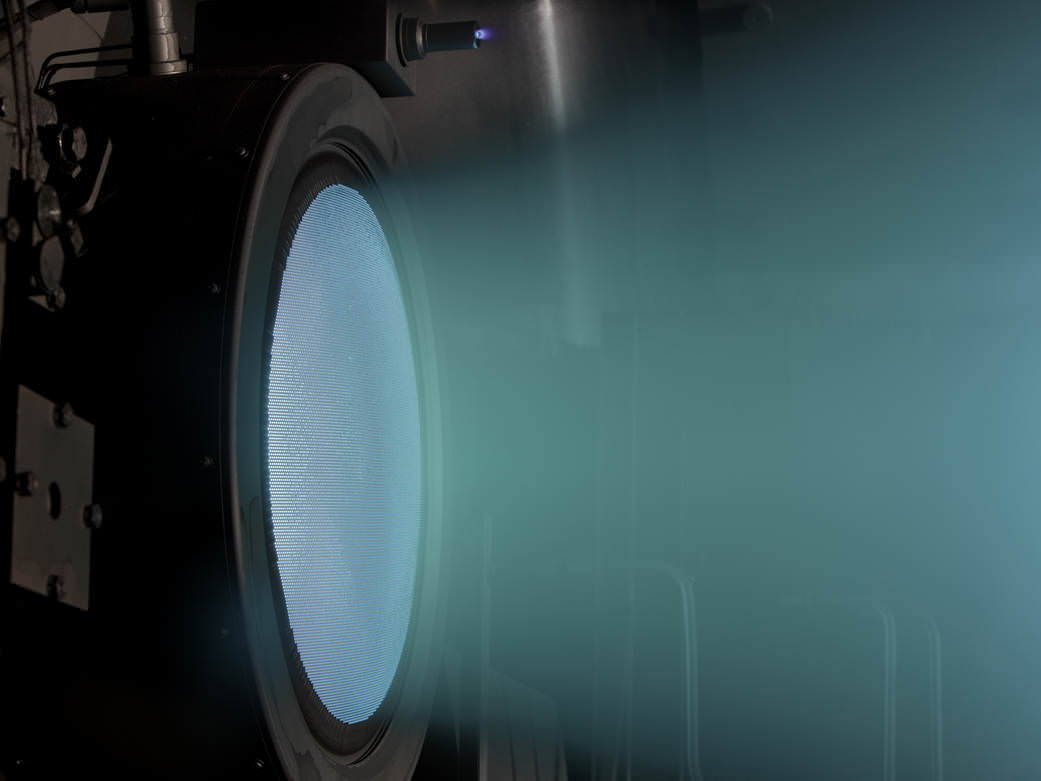
More details and illustrations can be found in Boxes.
Are they
flying? The EP systems are already performing missions in space, thus
accumulating invaluable experience and paving the way for the future. In
fact, these systems possess a long history that started in 190624, or more realistically, in 195025. The first ever EP flight tests using ablative pulsed plasma thrusters took place in 196426.
The first flight demonstration of the Hall thruster occurred in 1971,
and the subsequent flights have proven the high reliability and
efficiency of this type of the device27. Launched in 1998, the Deep Space 1 probe was accelerated by >4000 m/s using 2-kW ion thrusters28, which spent about 70 kg of xenon exhausted at a speed of 4 × 10⁴ m/s for near 2 years29. A similar system was installed on the gravity-ocean circulation explorer GOCE satellite in 200930.
Currently, the SSL SPT-100 Hall thruster subsystem is flying on 17
geostationary communication spacecraft, with an accumulated total flight
time of 40,000+ h9.
ADD Aerojet Rocketdyne on LM AEHF satellites Eutelsat has demonstrated
the EP system capabilities on two platforms (EUTELSAT 16C and KA-SAT),
and launched the full-electric platform EUTELSAT 115 West B in March
2015, for which EP was used for complete electric orbit raising. Two
more platforms (EUTELSAT 117 West B and EUTELSAT 172 B) will be also
launched31. The PROITERES-3 nanosatellite equipped with 30-W Hall thruster is planned for a one-way trip to the moon from low orbit21.
However, the long-expected era of electrically driven spacecraft has
yet to be realized, where the main obstacle lies in the relatively high
consumption of electric energy by the thrusters, requiring significant
enhancement in the thruster efficiency32.
Recently,
NASA has designed and performed the DAWN mission to investigate the two
main-belt asteroids, Vesta and Ceres, which are among the most massive
small planets. The DAWN mission was actually the ninth project of the
Discovery Program. Except for the gravitational maneuver in the Mars’
gravitational field, this mission was powered exclusively by an EP
system. The entire post-launch velocity gain ΔV required for the
heliocentric transfer to Vesta, then retardation to capture orbit at
Vesta, additional acceleration for changing orbits at Vesta, final
escape from orbit Vesta, then transfer to Ceres by heliocentric orbit,
retardation to capture orbit at Ceres, and the acceleration to change
orbits at Ceres was provided by the ion thrusters. The EP platform in
this mission has ensured the total velocity gain of ~11 km/s, and
~400 kg of xenon was spent during the entire mission28,33.
Another
important option for the application of EP systems is the control of
low mass (up to 100 kg) and miniature (Cubesats, up to ≈1 kg) satellites
that have a base form factor of a cube with the typical size of 0.1 m.
An internationally adopted standard in this field is the “Cubesat” by
California Polytechnic State University (CalPoly)34. Miniaturized but fully functional35,
highly efficient modern electronics ensure a wide spectrum of
capabilities even on such a small scale, thus enabling a great resource
economy due to low-cost launching using, e.g., small airborne systems
like the Orbital ATK Pegasus36.
The propulsion systems used on Cubesats usually provide a thrust of up
to 1 mN, with the consumed power of up to 100 W and the unit mass of
several kg37,38.
Recently, a so-called “satellite-on-a-chip” or “ChipSat” concept was
proposed with the aim to explore near-Earth space using the
ultra-miniaturized spacecraft in the form of monolithic semiconductor
integrated circuits, with a weight not exceeding 0.1 g (“smart dust”)39, as well as picosatellites (0.1–1 kg), and femtosatellites (up to 0.1 kg)40.
A large number of the ultra-miniaturized satellites (smart dust nodes)
forming an actively interacting distributed network could provide a
highly efficient solution for collecting, converting, and transmitting
large amounts of information41. Gas and thermal thrusters are not applicable in this case, and an EP system may be the only possible option42.
Are
they efficient? Yes, even at their present stage of development they
are quite efficient. The efficiency of contemporary EP systems reaches
10–35% for the most common power range of 100–300 W43, downscaling (depending on the design) to 6–15% in the power range of 50–100 W44. Larger thrusters demonstrate higher efficiency, reaching 40–60%45 at a power range of 1–3 kW and even 65% for higher powers46—these
are very large numbers for any heat engine. Nevertheless, significant
advances in power efficiency and controllability, as well as service
life are needed to make the EP systems the cornerstone of space
propulsion capable of highly efficient, robust operation under severe
space conditions for years.
As for now, significant efforts have
been made to enhance the performance, service life, and reliability of
the Hall thruster by means of sophisticated designs. Among others, the
two-stage Hall thruster was designed and tested47.
To ensure high performance at very high power levels reaching 100 kW, a
multiple nested thruster designs have been demonstrated20. Other design solutions such as cylindrical and annular Hall thrusters were proposed for the miniaturized devices44. More details on the methodology and problems related to scaling down EP devices could be found in the relevant publications48,49.
Nevertheless, further improvements are still required, where the major
advancements should definitely come from the material field.
How
can we boost their performance and service life? The performance of
contemporary EP devices can be boosted by the application of ultra-novel
nanoscaled materials and systems to significantly enhance work
capabilities and efficiency of all subsystems of the EP system and the
most important units of thrusters, including ion and Hall thrusters
specifically50.
Significant progress has already been achieved in the optimization of
the design, geometry, and magnetic field configuration of the thrusters;
however, further progress is vitally required to launch plasma
thrusters into orbit of a commercially efficient life, and we propose
and review here the use of surface-bound nanostructures and
nano-engineered surfaces as a next-generation approach to the
development of EP systems. Evidently, all the main challenges, namely
efficiency, lifetime, and process control of the thruster can be
significantly enhanced by the use of nanoscaled materials and
techniques.
There are other types of plasma thrusters potentially
suitable for Cubesats and even smaller satellites. While Hall-type and
gridded ion thrusters enjoy a relatively established reputation among
small orbit- and interplanet-tested systems, other types of EP devices
are just at the start of their road to the stars. The rise of Cubesats
and ultra-small (Picosats—<1 kg mass) satellites spurred
global demand for micro-N propulsors, and the first launches have
already proven their suitability and efficiency for the specific Cubesat
tasks—precise positioning, orientation, and orbit keeping with
µ-N pulses. These thrusters are designed to operate at ultra-small
thrust levels, providing a superior level of control over satellite
positioning and orientation; however, the material issues still play an
important role in their advancement and integration into existing and
emerging satellite systems51.
Nanomaterials in thrusters
Let
us now examine how to boost the properties and characteristics of the
thruster itself, which is the primary and critical sub-subsystem of the
entire EP platform.
Acceleration channel—what is the main
challenge? One of the major problems limiting the application of Hall
thrusters in space is the erosion of the ceramic wall caused by the
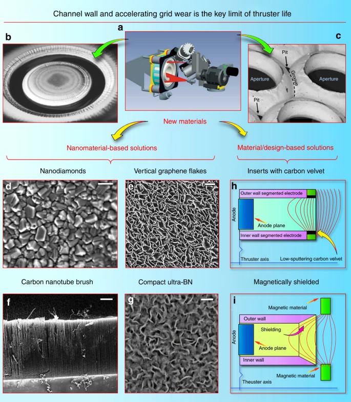
impact of the accelerated ion flux (Fig. 2)52. With the ion velocity reaching 10-–20 × 103 m/s, the wall wear is non negligible, significantly limiting the thruster life53. Currently, used boron nitride (BN) ceramics ensure remarkable operating characteristics but unsatisfactory service life;54 many researchers are currently dealing with this problem55.
Design efforts have aimed to reduce the wall wear, for example, by
using a cusp-type magnetic field that leads to a simplified (no internal
ceramic wall) channel geometry, thus lowering integral wear; however,
the wall material is at the heart of this problem. Table 1 provides a comparison of several most popular materials tested in the thruster conditions.
Ultrananocrystalline
diamond may be a promising approach to prolong service life. The first
possible attempt to reduce wall erosion is to use thin sputtered films
of a nanocrystalline wear-resistant material56
such as diamond. Polycrystalline chemical vapor-deposited diamond films
were tested on Hall thruster walls (on wear-affected areas), and have
demonstrated significantly better wear resistance without notable
degradation of the thruster performance and thrust57. Evidently, the choice of the wall materials
significantly affects the plasma discharge via changes in the secondary
electron emission, and more efforts should be applied to study all
aspects of this process; nevertheless, these encouraging results attract
special attention to the crystalline nanodiamond, which can be a very
promising candidate to address a significant increase in wear-limited
life. Indeed, it was demonstrated that the as-grown ultrananocrystalline
diamond films have wear coefficients roughly two orders of magnitude
lower than those of microcrystalline diamond films of comparable
thickness58. Other tests59
have demonstrated absent or negligible wear of the ultrananocrystalline
diamond films under conditions when other wear-resistant parts suffered
significant wear rates60. In mechanical tests, coatings of ultrananocrystalline diamond have demonstrated an order of magnitude longer lifetime61.
Such inspiring results obtained for the ultrananocrystalline diamond
suggest the need for extensive tests of ultrananocrystalline diamond
films for the wear reduction of the Hall channel walls. It should be
noted that the morphology and surface condition of the
ultrananocrystalline diamond strongly affects its tribological behavior62,
while the properties of the Hall thruster itself critically depend on
the wall conditions. Therefore, careful design and both experimental and
analytical examinations will be needed to implement this sophisticated
nanomaterial in the EP technique, and thorough testing of the actual
effect of energetic ion flux directly in the thruster channel is
required. Nevertheless, breakthrough results may be expected and the
thruster efficiency may be significantly boosted.
Even more
sophisticated nanomaterial with the promising wear-resistance properties
was also demonstrated. Specifically, the hot-filament chemical vapor
deposition was used to synthesize nanocrystalline diamond-coated silicon
nitride ceramics63.
This approach may be useful for enhancing the thruster wall wear
resistance and simultaneously adjusting the acceleration process
parameters, such as wall conductivity, roughness, secondary emission
coefficient, and others that directly influence the discharge64.
Carbon
can be also used for channel enhancement. One more promising approach
to reduce channel wall erosion is the use of carbon-based nanostructured
materials and surface structures. Carbon exhibits a very low sputtering
rate under the action of ion flux, as compared with the commonly used
BN ceramics65.
Along with this, the secondary electron emission yield of carbon is
also lower than that of BN, and this is also a useful feature that can
be a factor in Hall thruster operation66.
We should stress that BN demonstrates one of the best performances as a
wall material, so at the first stage, the aim should be the design of
the material that can at least preserve the efficiency of BN
state-of-the-art thrusters. On the other hand, increase of wear
resistance by the factor of 2 or 3 due to the wear-resistant carbon
films67 is attractive for enhancing the Hall thruster lifetime.
Carbon
nanotubes are also a promising technique to enhance channel wear
resistance. It is known that the graphene and graphene-based
nanostructures, such as carbon nanotubes, are very strong (strongest
known in nature) materials68.
The carbon nanotubes were also tested for resistance against ion flux
erosion. Specifically, the multiwall carbon nanotubes were tested as the
protective coating against plasma erosion in advanced space propulsion
systems. The polycrystalline diamond film was compared with multiwall
nanotubes, amorphous carbon, and BN films69.
Two types of nanotubes were investigated, including vertically aligned
nanotubes and those horizontally laid on the substrate surfaces. Only
diamond films and vertically aligned nanotubes survived erosion by
250 eV krypton ions of a flight-quality Hall thrusters69.
It
should be stressed that the use of carbon nanotubes in the thruster is
presently at the stage of an advanced concept that requires strong
efforts to check feasibility. Indeed, many properties specific to carbon
nanotubes, such as a decrease of the secondary electron emission in
vertically aligned structures and electrical conductivity of carbon
nanotubes can degrade the thruster characteristics. On the other hand,
carbon nanotubes are very attractive due to the properties of the carbon
material, and that material should obviously undergo active testing in
EP devices, taking into account the above-mentioned encouraging results
on wear resistance.
Thus, the dense brushes of vertically aligned
nanotubes demonstrate quite attractive and fascinating properties when
tested for wear resistance under the action of energetic ion flux in the
Hall thruster channel. Notably, the carbon nanotubes are conductive and
can change the acceleration mechanism (the wall conductivity is not an
inadmissible condition, but it significantly affects the process70). Undoubtedly, the first encouraging experiments67,69
force further complex investigations to cast light on the application
of carbon nanotube brushes and other graphene-containing materials in EP
engineering.
Graphene nanowalls is one more material potentially
capable of enhancing channel wear resistance. Along with the carbon
nanotubes, graphene and graphene flakes may be attractive for enhancing
the channel wall wear resistance. Graphene is the strongest material in
nature and carbon and carbon nanotubes are particularly resistant to ion
sputtering; this makes the surface-grown graphene flakes (nanowalls)
extremely attractive candidates for wear-resistance testing in the Hall
thruster channel. Dense patterns of carbon nanowalls can be formed
directly on the ceramic surface, with or without metal catalyst
particles71 if required. Direct growth on ceramic and metallic72 materials is also possible73. The exemplary graphene patterns grown on alumina are shown in Fig. 2,
left panel. They consist of nearly vertical graphene flakes attached by
one edge to the face surface of the ceramics, with the other edges
being open. Graphene nanowall patterns have not yet been subjected to
extensive ion flux and wear testing in real EP devices, but positive
results of the experiments with other carbon-containing, and especially
graphene-like and diamond-containing nanostructures, encourage further
work in this direction. Similar to other ultramodern techniques,
graphene and nanotubes should find their deserved place in EP
technology.
Table 1
shows a list of the presently used and tested materials and
nanomaterials for application as a coating on the acceleration channel.
Among then, the newly synthesized ultra-BN (uBN) material fabricated by
plasma-assisted CVD (chemical vapor deposition) process demonstrates
excellent wear and discharge efficiency characteristics. With extremely
low surface roughness and very low erosion coefficient (the total wear
rate of several nm × h−1, order of magnitude lower than that
of BN), the ultra-disperse uBN appears to be the best candidate for the
highly efficient, long-life thrusters. The operational tests of this
material are in progress, and a flight test is planned.
Apart from the material-related approaches, a so-called magnetic shielding technique was recently demonstrated74.
Sophisticated selection of the shape of the magnetic field at the exit
of the accelerating channel, and the proper profiling of the channel
exit ensure a significant decrease in the intensity of ion bombardment
to the channel walls, and hence, substantial decrease in the wear of
channel walls. As a result, the service life of the channel can be
essentially increased, thus significantly prolonging the thruster
lifespan without notable drop in the performance characteristics.
Schematics of the magnetic shielding technique is depicted in Fig. 2,
right panel. Importantly, magnetic shielding allows to operate the
thruster at higher voltage levels, i.e., the specific impulse that is in
general proportional to the discharge voltage could be increased.
Moreover, magnetic shielding partially precludes electrons from
contacting with the walls and hence, allows changing the wall material
(to metals or carbonaceous materials, or cheaper ceramics) without
reducing the thruster characteristics. On the other hand, this technique
requires more complex magnetic topology, which could make the EP system
somewhat more complicated and potentially less reliable. However,
potential significant benefits of this technique call for further
studies since the high-voltage operation requires new resistant
materials even in the magnetic shield mode. Further, both new materials
and sophisticated magnetic field topology are necessary to achieve the
dual-mode operation described in more detail below75.
Longer life and higher cathode current via advanced materials
Cathode
is the second electrode used in any type of static thruster to apply
negative potential to the discharge zone and in some cases, to supply
the flux of electrons to the discharge zone where they are magnetized,
as well as to compensate the space charge of (non-magnetized) ions; that
is why the cathodes on Hall thrusters are sometimes called
neutralizers. As a rule, a couple of cathodes (a working one and a spare
one) are usually installed outside of the main body of the thruster, as
shown in Box 2.
Cathodes may also be installed well outside the thruster (to ensure
better thruster characteristics) and thus will require strong protection76. Optimization of the cathode position is required to ensure the highest thruster performance characteristics77.
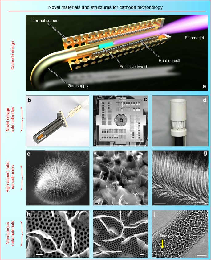
The cathode in the present-day thruster (see the schematic of the commonly used thermosemissive cathode in Fig. 3a)
is a very power- and current-loaded device, which should provide
reliable service for very long periods of time. One of the typical
cathodes with the LaB6 electron emitting insert (one of the
most common materials used in the emissive cathodes) was designed to
ensure the lifetime of 100,000 h at the discharge current of 40 A, thus
can be used to power a 12.5-kW Hall thruster under development for the
proposed Asteroid Redirect Robotic Mission78. The cathode can be used as a low thrust thruster itself79. Cathode erosion also represents a problem reducing the service life80.
Thus,
the key challenges for the cathode (and consequently possible
directions for the enhancement of thruster efficiency via upgrading the
cathode unit) consist in the reduction or total elimination of
propellant consumption via the cathode, significant boost of the cathode
service life, and the reduction of heat loss from the incandescent
parts.
Can nano help here? Let us examine how nanomaterials and nanotechnology can help achieve these goals.
Reduced
gas consumption may be ensured through the use of nanoporous materials,
nanotubes, and graphene. The best solution for this problem is the
total elimination of gas flux through the cathode by using high-emissive
materials and surface structures. Numerous tests have demonstrated that
usual solid and microporous materials cannot ensure notable enhancement
of characteristics compared with the commonly used LaB6
material. However, encouraging experimental results have been obtained
by testing various nanostructured and surface-engineered materials, such
as nanoporous metal emissive elements (Fig. 3b). Carbon nanotubes were also successfully tested as field-emission electron sources operating without or at reduced gas supply81 (Fig. 3c
shows the photograph of carbon nanotube cold cathode installed on a
Hall effect thruster). Moreover, multiwall carbon nanotube emitters were
tested directly for the use in spacecraft cathode units;82 the tests were conducted specifically for the operation in the Hall thruster plume environment83. Other nano-engineered materials also demonstrated promising electron emission properties, e.g., ultrananocrystalline diamonds84 and nanocrystalline diamond-coated silicon tip arrays85. Nano- and micro-engineered materials relevant to EP were also tested for their electron emission capabilities86. Vertically aligned graphene87 has also demonstrated inspiring results in electron emission tests88.
Investigations related to the reliability and failure mechanism of the
carbon nanotube-based cathodes are also undergoing active exploration89.
Therefore, carbon nanotubes (both single- and multi-walled) and
vertically aligned graphene flakes are good candidates for significantly
enhancing thruster efficiency due to the propellant-free regime (we
recall here that the propellant consumption by the conventional
incandescent cathode can reach 10% for small thrusters, and usually
accounts for 3–5% of propellant consumed for larger devices). In spite
of many successful experiments referenced here, more efforts are
required to utilize the full potential of vertically aligned
nanostructures in cathode-related applications, and newly developed
nanostructures and patterns can be much more efficient than those
already tested classical cathodes with a heating coil and an emissive
La-B insert (Fig. 3d).
An
example of a novel and potentially efficient nanomaterial for cathodes
is the cluster-grown carbon nanotubes and nanocrystalline graphites.
These clusters could be arranged into various shapes by a simple
mechanical drawing (using e.g., mechanical tools or a laser beam) of the
required configuration on the surface. Figure 3e, f, g
show the SEM (scanning electron microscopy) images of nanotube and
nanocrystalline graphite clusters. Such aggregates are extremely
promising for emission-related applications. Scanning and transmission
electron microscopy characterizations show that the longest nanotubes
reach several hundred microns in length, the array density reaches 1000
nanotubes per l μm2, and diameters of the nanotubes were in
the range of 15–50 nm, with up to 20 walls. Importantly, dense linear
brushes of nanotubes could be produced over the entire sample size of
10 mm. More detail about the growth process can be found elsewhere90.
Further studies of these and other nanotube and graphene patterns and
surface structures are needed to make a definitive conversion from
contemporary propellant-consuming cathodes to novel, cold,
propellant-free nanomaterial-based cathodes. More examples and a
detailed description can be found in Fig. 3.
When
the propellant-free design is inapplicable, complex nanostructure-based
surface systems (metamaterials) may be proposed for application in
thruster cathodes, with one of the example systems shown in Fig. 3h, i. A dense pattern of the vertically aligned graphene flakes was grown on the nanoporous91
alumina membrane. Propellant can be supplied directly through the
nanoporous alumina, and electrons will be emitted from the acute edges
of the graphene, which are emission-capable structures as was
demonstrated in direct experiments88.
Longer
life of cathode could be also reached by the use of ultra-nanoporous
inserts. Emissive inserts work when electrons exit an emissive material
from the surface; hence, larger surface area per volume unit of the
insert could be beneficial due to the lower required heated volume and
more efficient electron emission. Here, we demonstrate an example of
ultra-nanoporous highly-crystalline nanowires with uniformly distributed
nanopores in the 3 nm range produced by electron beam exposure (Fig. 3j). In the example, single-crystalline MoO3 nanowires were synthesized by a simple, environmentally friendly plasmoxy-nanotech process92
by direct exposure of a pure Mo foil to reactive oxygen plasmas in a
Pyrex glass reactor. After synthesizing the single-crystalline MoO3
nanowires, they were transferred to the transmission electron
microscopy grid for the electron beam irradiation. This method is based
on the electron beam-driven oxide-to-sub-oxide and then
sub-oxide-to-metallic transition that can be controlled by the electron
beam exposure. The diameters of the resulting pores range from 2 to
5 nm, with a Gaussian-like distribution and an average size of around
3.6 nm. More details on the process and performed characterizations can
be found elsewhere93.
This nanomaterial brings together several beneficial properties, namely
a unique ultra-nanoporous structure (nanopore size of 2–5 nm) and an
extremely high porosity coefficient reaching 0.75. This technique can
potentially be used to produce other materials, including those suitable
for the emissive inserts, and very efficient inserts may be fabricated.
Nanoscaled
metamaterial could help to reduce the heat losses. The incandescent
cathode wastes a great deal of heat energy through radiation from the
cathode’s hot parts into space. However, ideally, the entire heat
generated in the cathode should be used within (at the emissive insert)
and should not be released from the outer parts of the unit. Any type of
currently used heat protections essentially provides passive
protection. Using nanoscaled metamaterials, active heat protection
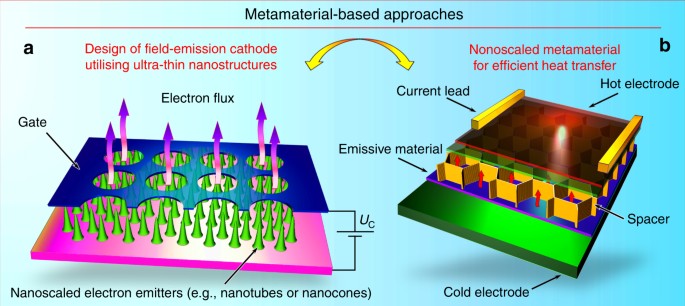
physically based on heat pump principles can be designed. Specifically,
external energy should be spent to transfer the heat from colder parts
to heated parts by, e.g., nanoscaled high-temperature metamaterial
capable of reversal heat transmission94.
During the metamaterial operation, an electrical potential dependent on
the distance between surfaces and the current density is applied
between the anode and the cathode to sustain the current in the gap. As a
result, heat may be transferred from the hot surface directly to the
colder part by the electron current in the gap, i.e., this metamaterial
works as an electronic heat pump. As a result, heat that leaks from the
hot cathode to space can be significantly reduced. We stress that this
is only a concept under active investigation95.
Further investigations will be needed to design, test, and implement
the novel heat-transferring systems in the material form factor. A
schematic of the metamaterial proposed for the active heat pumps is
shown in Fig. 4.
Adaptive and self-healing thruster via nanomaterials
As
previously mentioned, the nature of the wall material can be used to
classify Hall-type thrusters as TAL featuring metallic channel walls,
and thrusters with ceramic walls (stationary plasma thruster, SPT).
These two types exhibit slightly different characteristics and require
somewhat different design approaches, and as such, these devices could
occupy specific application niches and be successfully used in space
exploration for various missions. In general, the total difference in
performance between ceramic-walled SPT-type thruster and metal TAL is
not so significant. Nevertheless, both types are attracting attention,
and among other advantages, TAL can ensure efficient operation at higher
(up to several kV) voltage, so the specific pulse (exhaust velocity)
will be higher. In turn, this may be advantageous for the missions
requiring elevated specific impulse at somewhat lower thrust, such as
orbit keeping or debris removal96
for several years at limited onboard power and limited mass. At
present, the TAL-type thrusters are underexplored, yet numerous studies
indeed demonstrate their better operability at significantly increased
voltages97,98.
Even within the same thruster type, the wall material characteristics
may influence thrust, exhaust velocity, and thruster efficiency99,100.
Evidently,
TAL is not congruent to a standard SPT thruster with conducting walls,
and apart from the wall material state, some other adjustments (e.g.,
shift of the anode to shorten the discharge zone to the TAL-optimized
configuration, reshaping the magnetic field by switching coil sections,
and so on) will be required to ensure efficient TAL operation in the
proper mode, i.e., in the anode layer regime; nevertheless, such
transformations appear to be quite attainable in flight101.
Is
it possible to actively control processes in thrusters by
nanomaterial-based techniques? Evidently, many of the present-day
nanomaterials and surface-engineered systems could be tested for the
active control of the thruster operation. Acceleration channels made of
various materials such as solid BN, diamond- or ultrananocrystalline
diamond-coated walls, or carbon nanotubes/graphene-protected surfaces
can exhibit notably different surface morphologies, roughness, and
electrical conductivity, and importantly, reasonably distinct electron
emission features also determined by the presence of acute tips (e.g.,
on carbon nanotubes), sharp edges (e.g., on graphene flakes), and sharp
facets (e.g., on nanodiamond crystals). Undoubtedly, control of such a
set of unique properties can lead to thrusters with a wide operational
range, and moreover, could allow adaptive switching between the
operational modes.
Importantly, most of the nanostructures and
nanomaterials mentioned above are routinely fabricated, or could be
fabricated using low-temperature plasmas with properties that are quite
similar to plasma properties within operating Hall thrusters,
specifically: plasma density of ≈1018–1019 m−3,
electron energy up to 10–20 eV, and process voltage of about several
hundreds of volts. Granted that different feedstock gases must be used
to accomplish propulsion or nanosynthesis, we still find the
similarities quite encouraging. Indeed, Hall thrusters have already been
successfully tested for nanofabrication, and hence, desired
nanostructures and nanomaterials could be in principle synthesized
directly in the discharge (acceleration) channel.
Thus, we propose
the concept of the so-called adaptive thruster, i.e., the thruster that
is capable of changing the main discharge type (thruster type) by
actively adapting the channel wall parameters by synthesizing required
nanomaterials in its own discharge, then depositing them onto specific
locations inside the channel, and finally modifying the channel wall
surface characteristics by direct interactions with its own channel
plasma. In more detail, the electric, magnetic, and gas supply systems
of the thruster should be designed and tuned to be capable of ensuring
temporary transition of the discharge from acceleration to nanosynthesis
mode (changing the gas composition by adding the nanomaterial precursor
such as, e.g., methane and hydrogen for carbon nanotube, graphene, or
diamond synthesis, and preprograming synthesis protocol) to ensure
optimum nanomaterial nucleation and growth conditions, and restoring
discharge to the acceleration mode after adjusting the channel wall to
the new required thrust/velocity conditions.
Graphane can be a key
material to realize this task. The ability of switching between TAL and
SPT operational modes is a possible implementation of an adaptive
thruster concept. As the wall material (a ceramic or a metal) is the
major discriminant of these modes, the thruster ability of adapting the
conductivity of its own wall material would enable the realization of
adaptive features. For instance, hydrogenation of the surfaces of
graphene flakes on the channel walls by the thruster discharge plasma
may ensure quick and reversible transition from insulating to conductive
states and vice versa, thus would provide the ability to switch between
TAL and SPT regimes directly in flight and possibly, without
interruption of the thruster operation. Indeed, it was already
demonstrated that graphene can react with atomic hydrogen, and this
reaction transforms graphene (which is a perfect electrical conductor)
into graphane, an insulator made out of a two-dimensional compound of
carbon and hydrogen (i.e., hydrogenated graphene)102.
This reaction is also reversible, and the graphene structure is
maintained when graphane is formed by attaching hydrogen atoms to
graphene. Importantly, this reaction requires low-temperature plasma
similar to that present in the Hall thruster discharge. In the original
experiment103,
10% admixture of hydrogen in argon was used to convert graphene into
graphane. Thus, by changing the plasma parameters in the thruster
discharge, it is possible to change the conductor/insulator state of the
acceleration channel surface by depositing graphene flakes. Xenon,
which is commonly used in EP is similar to argon (both are inert gases
with close ionization potentials and both sustain the discharge in
crossed E × B fields at similar voltages), could be considered as
suitable for a similar hydrogenation process. The hydrogen admixture in
the gas of an operating thruster could be short, since only surface
hydrogenation is required. As hydrogen source, metal hydrides (i.e., MgH2)
can be used. At present, there is no scientific evidence regarding
graphane behavior under the effect of the energetic ion flux, but
encouraging results show that graphane is relatively stable (as it
requires annealing for at least 24 h at 450 °C)103.
Both vertically aligned graphene flakes, as well as graphene-like
inlaying films can be proposed for adaptive thruster applications. In
any case, the use of such materials should be explored due to the
potential importance of the proposed in-operation and in-flight
conversion of TAL to SPT.
Alternatively, an insulating film could
be temporarily deposited onto the metal walls to transform a TAL-type
device into a SPT-type. For this purpose, a small amount of silane
(silicon and hydrogen containing gas, SiH4) and oxygen (or
e.g., water vapor) can be premixed with the inert propellant (xenon).
Indeed, it was already experimentally demonstrated that addition of
silane (10 p.p.m. only) in the low-temperature plasma results in the
efficient nucleation of silicon nanocrystals with the characteristic
size of several nanometers104. Figure in Box 4
shows the experimental setup, as well as a photograph of the discharge
and a scanning electron microscopy image of the nucleated silicon
nanoparticles (mean diameter <5 nm). By tailoring the plasma
properties, different nanoparticle characteristics, such as chemical
composition and crystal structure, can be achieved. Oxidation can then
be easily achieved with a very small amount of oxygen or even water
vapor105.
The
application of a thin metal film onto the channel wall surfaces from
the discharge plasma is another approach to adaptive thruster systems.
Indeed, this approach will require admixture of a metal-containing gas106 or evaporated metal-containing liquids107
capable of producing suitable metal precursors in the discharge. A
metal film deposited onto the wall surface will ensure the transition
from insulating to conductive states, but the wear resistance of pure
metal is low and thus could be used for short-term regime switching.
Deposition
of such oxidized nanoparticles onto the metallic walls of the
acceleration channel will create electrically insulating layer and thus
transform the TAL device into SPT. Notably, Hall thrusters with a
significant addition of silica on the channel walls is quite functional,
albeit with somewhat lower efficiency.
Is it possible in a real
thrusters? Yes, provided that an efficient control over the processes in
plasma-wall sheath is ensured, e.g., by the magnetic shielding that was
encouragingly demonstrated for the thruster channel. Proper control of
the plasma configuration108
could make it possible to temporarily separate the main discharge zone
from the nanoparticle nucleation and deposition area, thus ensuring
direct growth of the nanostructures in the discharge and the following
deposition onto walls. Extended experimental and theoretical studies
will be required to bring these concepts to life.
Using similar
design solutions, it is possible to fabricate electrodes with, for
instance, thin layers of carbon mixed with layers of traditional BN.
Such sophisticated structures enable active control over the near-wall
conductivity109,
and hence, enhance the discharge and ion acceleration. Furthermore, the
replacement of thin carbon layers with the graphene (and possibly,
multi-walled graphene flakes110 could potentially enhance the characteristics due to higher mechanical strength, as well as electrical111 and heat conductivities, intrinsic to graphene112).
Perspective
The
NASA’s 2015 Nanotechnology Roadmap includes, among other important
concepts, a new paradigm of paramount importance, a so-called concept of
a self-healing spaceship. This covers several mainlines, in particular
self-cleaning surfaces, self-healing repair mechanisms, and
self-repairing surfaces and materials. Initial research efforts by NASA
and associated research institutions have demonstrated self-healing
materials that were capable of repairing the punctures in several
seconds113.
Moreover, other possible self-healing approaches for EP systems were
explored; at the thruster level, self-healing field-emission
neutralizers (cathodes) for EP devices were developed by NASA in
collaboration with Aerophysics, Inc. in the framework of the NASA Small
Business Innovation Research (SBIR) contracts114.
The
implementation of self-healing and self-restoring materials and systems
to the entire spacecraft makes the self-healing approaches compulsory
for subsystems such as thrusters that are the critical elements of the
propulsion system. Furthermore, just the wear-affected acceleration
channel walls that actually limit the thruster life are the ultimate
elements to be examined in terms of incorporation of self-healing
materials and techniques. Apparently, we are currently at the stage of
problem formulation and determining the general angle-of-attack to
ensure the development of the most general approaches; nevertheless,
reasonable efforts are to be applied now in the framework of the NASA’s
self-healing spaceship concept.
Specifically, we are proposing the
self-healing approach (plasma-enabled healing) similar to that
suggested for modification of the acceleration channel material and
in-flight switching mode of thruster operation between the TAL and SPT
regimes; specifically, self-healing should be enabled by plasma
nucleation and deposition of various nanostructures and nanomaterials.
The difference is that in the case of self-healing, the deposition of
plasma-nucleated nanomaterials (most probably, as small as possible) or
appropriate ions (e.g., silicon oxide formed in plasma with silane
added) should be ensured at proper places (in wear damage locations
only), and moreover, certain surface processes should be activated and
sophisticatedly controlled to conduct efficient wall healing, i.e.,
surface repair by the controlled re-deposition of the nanomaterial.
Importantly, the first experiments have demonstrated this mode in the
thruster-like conditions115.
Two
different regimes of the thruster self-healing operation may be
considered, depending on the specific wall material, propellant,
thruster type, and plasma parameters, namely the concurrent mode
self-healing conducted continuously during the thruster work (the worn
areas are restored immediately after reaching some detection threshold),
and the sessional mode based on healing/restoration sessions conducted
periodically, when the wall wear reaches the critical point affecting
thruster’s operational characteristics.
In any of the above modes,
several key processes should be activated and controlled, such as
nucleation of the appropriate nanoscaled particles (most probable for
the sessional self-healing) or appropriate ions (for concurrent
self-healing); delivery of thus-formed particles to the most appropriate
locations (i.e., to the most worn spots on the wall surfaces), this is
important for both concurrent and sessional modes; and surface processes
such as material diffusion, coalescence, and incorporation in the
elements of wall surface (worn pits), ensuring efficient repair of the
plasma-affected surfaces. Thus, the general route could be formulated as
nucleation → delivery → repair.
Detailed examination of all these
processes is obviously outside the scope of our work, the aim of which
is to set the general directions, suggest potential approaches, and
stimulate discussion within this highly promising area of research.
Nevertheless, we would like to take this opportunity to point out and
briefly characterize the physical mechanisms at the heart of the above
process. We should highlight that surface self-healing is essentially a
manifestation of self-organization116 and self-assembly;117 moreover, self-healing is a surface-based self-organizational process118 and plasma exposure can effectively produce strong driving forces119 to drive self-organization on surfaces120.
Nucleation
of the appropriate nanoscaled particles was in short discussed in the
above subsections, and it was shown that the nucleation of various
nanostructures and nanocrystals is possible in the plasma environment
similar to that of the present-day Hall thrusters104.
The
delivery of plasma-nucleated charged nanostructures to the most
appropriate locations, as well as surface processes such as diffusion
and material incorporation, could be achieved via non-uniform electric
fields that develop at the plasma-solid interface and in particular
enhanced by rough surface. It was already demonstrated that electric
field could control movement of ions and nanoparticles near surfaces,
and eventually ensure material deposition onto preferred locations
within the nano-textured surface pattern121. Detailed numerical simulations of the electrical field patterns (Figure in Box 4)
and irregular fields of adsorbed atoms (adatoms) on the plasma-exposed
rough surfaces were verified by experimental studies on the
plasma-driven surface restructuring and confirmed intense
self-organization processes122 under actions of low-temperature plasma35 and surface electric potential123.
Briefly,
strong peaks of the near-surface electric field and adatom density
causes rapid, intense material redistribution resulting in healing of
worn traces by filling them with the repairing material. Importantly,
the efficient incorporation of the repairing material into the worn
traces requires plasma and electron irradiation for degasing of the
surface and for the creation of dangling bonds124.
In general, surface-based processes are relatively well described and
numerous studies were conducted to show how the plasma composition,
surface temperature, and other parameters influence surface
restructuring. Ultimately, special arrangements should be designed to
fully control the entire process, e.g., heaters for ensuring the optimum
temperature and additional aids to adjust the magnetic field during the
self-healing session.
Apparently, significant stumbling blocks
and constraints should be expected during implementation of adaptive and
self-healing thruster strategies. Indeed, the adaptive and self-healing
strategies for boosting mission efficiency and significant extension of
the thruster lifetime would clearly complicate the entire system and
hence, disadvantages should be carefully considered and taken into
account. Moreover, not every thruster system could be suitable for such
an upgrade, and it is quite possible that the drawbacks related to the
increase in weight and complexity, and consequent lower weight
efficiency and lower reliability could make some systems not appropriate
for the adaptive and self-healing technologies.
In general, the
alternative approach could include redundancy (installation of
additional thrusters to prolong the life of the entire system and change
the operation mode by switching the thrusters), which is commonly used
in similar complex technical systems. Evidently, a detailed systematic
analysis will be required in each specific case to determine the
applicability and practicability of the adaptability and self-healing
strategies, based on a spectrum of parameters. Indeed, compromise
between mass increase due to additional thrusters, connections, frames,
and so on, in the case of the redundancy approach, and mass increase due
to additional gases, gas tanks, valves, power supply units, control
systems, and so on, will be required to maintain adaptability and
self-healing processes. Moreover, compromise between life increase due
to self-healing and life decrease due to lower reliability of the whole
system after introduction of additional self-healing subsystems should
also be considered.
Detailed systematic analysis should be
performed in each specific case and specific mission, and possible
stumbling blocks and constraints should be detected, analyzed, and
assessed to consider the applicability of the adaptability and
self-healing techniques and their benefit against the increased
complexity. Indeed, the self-healing and self-adjusting space system
will represent a next level of complexity, in fact being in part a
biomimetic system.
Moreover, the study of the critical processes
within an adaptive and self-healing space thruster system presents a
considerable experimental challenge, with significantly more effort
required to first demonstrate some self-healing functions at the system
level. However, given the potential benefits, this is a worthwhile
effort since it could potentially revolutionize the entire approach to
designing and building the spacecraft systems and other space-based
platforms. Furthermore, while creation of the flight-ready self-healing
thruster is a scientific and engineering challenge of immense
complexity, the state-of-the-art techniques make it conceptually
possible.