 |
| AWESs. Example of Ground-Gen (a) and Fly-Gen (b) AWESs. |
Summary Overview
There are various aspects of Airborne Wind Energy Systems (AWES), which are an emerging renewable energy technology that harnesses wind power at higher altitudes than traditional wind turbines. The key points are:
1. AWES use tethered flying devices like kites, wings, or drones to convert wind energy into electricity. There are two main types: Ground-Gen systems that generate electricity on the ground using the tether's mechanical motion, and Fly-Gen systems that produce electricity on the flying device and send it down the tether.
2. Compared to traditional wind turbines, AWES can access stronger and more consistent winds at higher altitudes, have lower material costs, are easier to transport and install, and have reduced visual and environmental impact. However, the technology is still immature with challenges related to reliability, durability, tether drag, intermittency, and regulatory issues.
3. Several companies and research institutions worldwide are developing AWES prototypes, including Makani Power, Ampyx Power, SkySails Power, Kitemill, and Altaeros Energies. SkySails launched the first commercial AWES in Mauritius in 2021.
4. Crosswind flight, where the flying device moves in a figure-eight pattern perpendicular to the wind direction, is key to generating high power output. Basic models show that AWES power output depends on factors like wing area, aerodynamic efficiency, and wind speed.
5. The U.S. Department of Energy sees significant potential for AWES and proposes a 10-year research and development plan to advance the technology. With further progress, AWES could play an important role in expanding wind power, especially in remote locations or offshore.
AWES Developers
- KiteGen Research (Italy):
- - Developed the "KiteGen Stem" concept, a pumping kite generator with a nominal power of 3 MW.
- - Also working on a vertical axis generator concept and an offshore AWES design.
- Makani Power (USA):
- - Developed the "Airborne Wind Turbine" (AWT) concept, a Fly-Gen AWES with onboard turbines.
- - Currently developing a 600 kW prototype called the "M600" and planning a 5 MW offshore version.
- Ampyx Power (Netherlands):
- - Developed a pumping kite generator system using a fixed-wing glider.
- - Currently developing and testing a 5.5 m wingspan "PowerPlane" prototype and planning a larger 2 MW system.
- SkySails Power (Germany):
- - Developing a pumping kite generator system based on their kite propulsion technology for ships.
- - Working on a mobile AWES with a capacity between 250 kW and 1 MW and an offshore AWES with a capacity from 1 to 3.5 MW.
- TU Delft (Netherlands):
- - Conducting research on various AWES concepts, including pumping kite generators and rigid-wing systems.
- - Collaborating with Karlsruhe University of Applied Sciences on a 20 kW pumping kite generator.
- Altaeros Energies (USA):
- - Developing a stationary Fly-Gen AWES using a helium-filled aerostat with a wind turbine inside.
- - Tested a small-scale prototype and working on larger systems for remote power applications.
- Kitemill (Norway):
- - Developing a pumping kite generator system using a rigid-wing glider.
- Enerkite (Germany):
- - Developed a 30 kW pumping kite generator and working on 100 kW and 500 kW systems.
- Joby Energy (USA):
- - Developing a Fly-Gen AWES with multiple turbines mounted on a multi-wing frame structure.
- Windlift (USA):
- Developing a pumping kite generator system using soft kites, targeting off-grid and remote power applications.
AWES advantages
1. Access to stronger and more consistent winds at higher altitudes: AWESs can reach winds at altitudes between 200 meters and 10 kilometers, which are generally stronger and more persistent than winds at lower altitudes.
2. Potential for higher energy generation: The crosswind flight mode employed by many AWESs can theoretically generate power one or two orders of magnitude higher than non-crosswind generation.
3. Reduced material costs: AWESs use tethered flying devices instead of large, heavy towers and foundations, which can lead to significant reductions in material costs.
4. Easier transportation and installation: The lightweight and compact nature of AWESs makes them easier to transport and install compared to traditional wind turbines, especially in remote or offshore locations.
5. Lower visual and environmental impact: AWESs have a smaller visual footprint and potentially lower environmental impact due to their reduced ground presence and the ability to adjust their flight paths.
6. Potential for deployment in deeper offshore waters: The reduced weight and size of AWESs may enable their deployment in deeper offshore waters, where the installation of traditional wind turbines is more challenging and expensive.
7. Complementary power generation: AWESs could potentially complement solar PV or other renewable energy sources in microgrids or remote locations, providing a more diverse and reliable power supply.
While these advantages make AWESs a promising technology, it is essential to note that they are still in the development stage, and further research and validation are needed to fully realize their potential.
Disadvantages and Limitations
1. Technological immaturity: AWESs are still an emerging technology, and most concepts are in the early stages of development. There is a lack of convergence on the optimal design, and no full-scale commercial systems have been deployed yet.
2. Complexity of control and autonomous operation: Controlling the flight path and maintaining the stability of AWESs is challenging, especially in varying wind conditions. Fully autonomous operation, including take-off, landing, and collision avoidance, is crucial but has not been demonstrated for extended periods.
3. Reliability and durability concerns: AWESs are subject to high mechanical stresses and extreme weather conditions, which can affect the reliability and durability of the system components, particularly the tethers and flying devices.
4. Tether drag and losses: The tethers used in AWESs introduce aerodynamic drag and power losses, which can significantly impact the overall system efficiency. Developing low-drag tethers or reducing tether length while maintaining high altitudes remains a challenge.
5. Intermittency and variable power output: Some AWES concepts, particularly those with fixed-ground stations, have a highly discontinuous power output due to the periodic nature of the generation and recovery phases. This intermittency may require additional energy storage or rectification measures.
6. Regulatory and safety concerns: The operation of AWESs raises concerns related to airspace regulations, collision risks, and potential interference with aviation and radar systems. Establishing a clear regulatory framework and safety standards is essential for the widespread adoption of AWESs.
7. Uncertain economic viability: The economic competitiveness of AWESs compared to traditional wind turbines or other renewable energy technologies is yet to be demonstrated. The scalability, reliability, and lifetime of AWESs will significantly impact their levelized cost of energy (LCOE).
8. Limited knowledge of high-altitude wind resources: While high-altitude winds are generally considered stronger and more consistent, there is still limited data and understanding of the specific wind characteristics and their variability at different locations and altitudes relevant for AWES operation.
Addressing these challenges and limitations through further research, development, and demonstration efforts will be crucial for the successful commercialization and widespread deployment of AWESs.
Energy From the Sky: How Drones Can Generate Electricity
scitechdaily.com
Summary
Key points:
1. AWES use tethered drones to harvest wind power at higher altitudes than conventional wind turbines, potentially contributing to the UK's net-zero objectives.
2. The complex system of AWES requires intricate flight patterns and is subject to strong aerodynamic forces, making it challenging to control and operate safely.
3. The project aims to address these challenges by using bifurcation and continuation methods, which have been successfully used in aircraft dynamic studies to predict dangerous behaviors.
4. Improving AWES safety and efficiency could lead to significant cost savings and improved performance, bringing the technology closer to commercialization.
5. The project collaborates with Norwegian startup Kitemill and University Carlos the III of Madrid, and it has the potential to advance the UK's net-zero mission while securing British competence in this emerging sector.
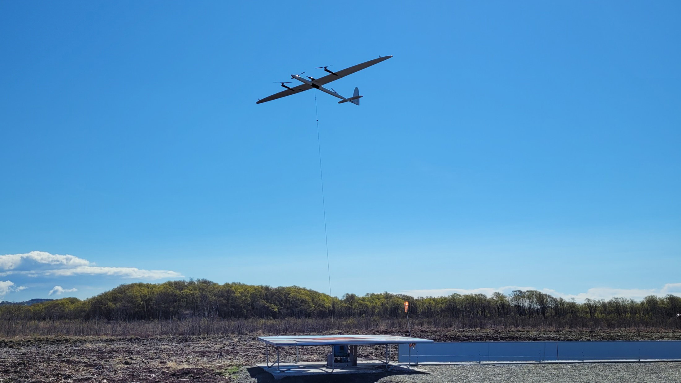
New research into Airborne Wind Energy Systems, funded by a substantial EPSRC grant, seeks to harness high-altitude wind energy using drones, aiming to overcome challenges in system stability and enhance commercial viability, supporting the UK’s net-zero goals. Image of a prototype Kitemill drone in action. Credit: Kitemill
Dr. Duc H. Nguyen has received funding to research Airborne Wind Energy Systems, aiming to improve their safety and efficiency for potential commercialization and a significant role in achieving the UK’s net-zero emissions.
Drones could be crucial in achieving the UK’s net-zero objectives by harvesting wind energy. Dr. Duc H. Nguyen, a Lecturer in Flight Dynamics and Control at the University of Bristol, has received a £375,000 grant from the Engineering and Physical Sciences Research Council (EPSRC) to further explore Airborne Wind Energy Systems (AWES).
By tethering a drone to a ground station, AWES harvests wind power at higher altitudes than conventional wind turbines. The high wind pulls the drone away from the ground station, driving the generator, and producing electricity.
This technology can benefit the UK’s energy sector by reducing its carbon footprint, providing offshore and onshore flexibility, and enhancing the ability to operate in remote areas.
To generate the most power, AWES must fly in intricate patterns while subjected to strong aerodynamic forces. This arrangement creates a complex system with delicate handling characteristics – a slight miscalculation could send the drone tumbling to the ground.
This is the challenge that Dr Nguyen and his collaborators hope to solve during this project. By improving AWES safety and efficiency, he hopes the project will pave the way for AWES commercialization.
Potential and Pitfalls of AWES
Dr Nguyen, from the School of Civil, Aerospace and Design Engineering, explained: “Airborne wind energy has enormous potential and is anticipated to generate €70 billion per year worth of electricity by 2050. However, it is still an emerging technology. In many cases, a trade-off has been made: new designs have been rapidly deployed for test flights before their flying characteristics are fully understood. This has prevented many AWES prototypes from achieving full capacity in operation, leading to early termination of the program and hindering commercialization. This project seeks to address this challenge through the use of bifurcation and continuation methods.”
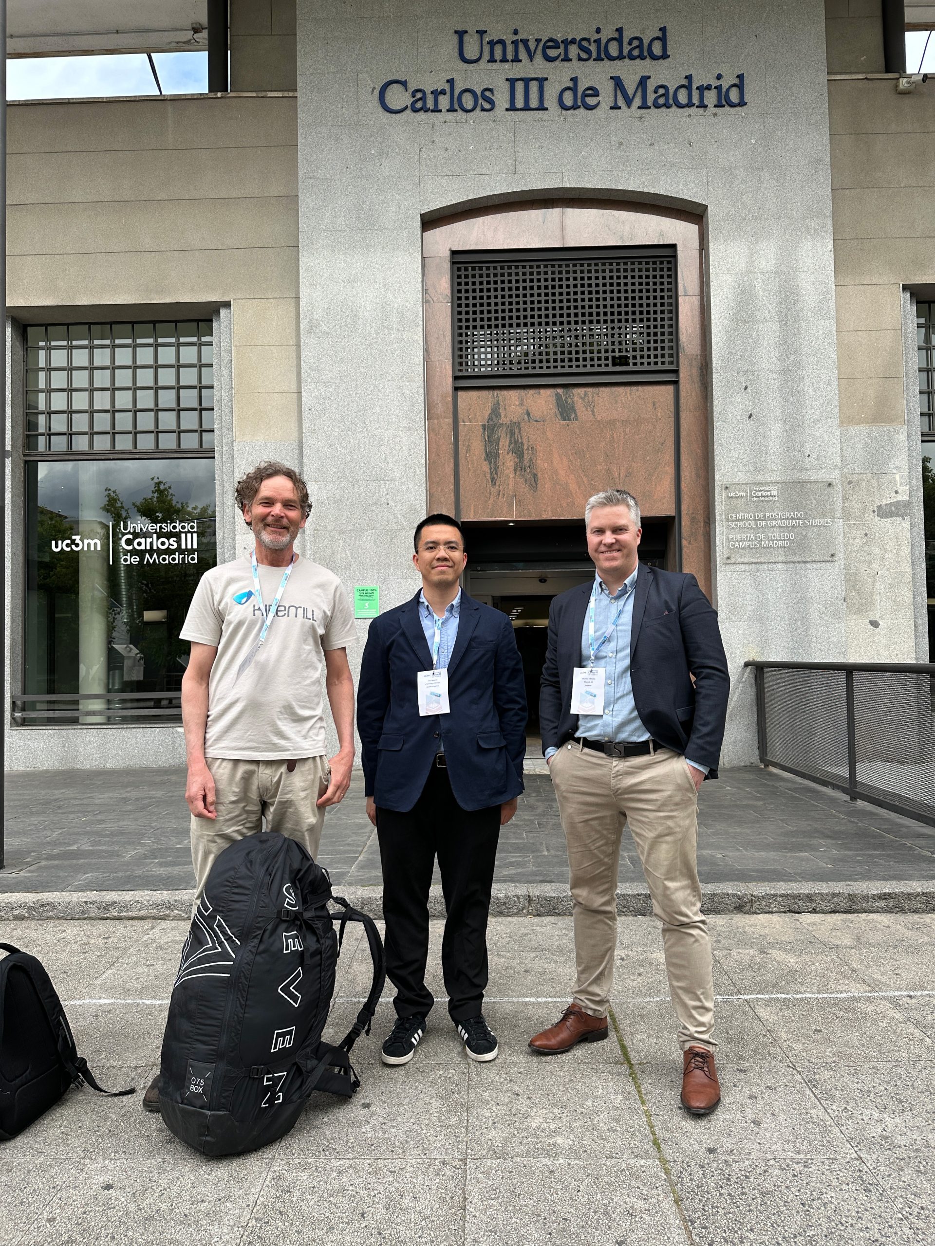
Dr. Duc Nguyen with Kitemill’s founders, Jon Gjerde (left) and Thomas Hårklau (right), at the Airborne Wind Energy 2024 conference. Credit: Kitemill/Dr Duc Nguyen
These numerical techniques have been successfully used in aircraft dynamic studies to predict dangerous behaviors such as pilot-induced oscillation, flutter, and spin.
Dr. Nguyen concluded: “By replacing existing techniques with bifurcation methods, AWES can achieve significant cost savings and improved performance that will ultimately bring this technology closer to commercialization.”
In addition to the EPSRC funding, the project also benefits from collaborations with two leading players in the sector, Norwegian startup Kitemill and University Carlos the III of Madrid.
Thomas Hårklau, co-founder and Chief Executive Officer of Kitemill, added: “The initiation and successful funding of this AWES project is an important development in the renewable energy sector. AWES technology, with its exceptional material efficiency and higher energy yields, has the potential to become a dominant force in the energy industry. We are excited to collaborate with Duc Nguyen and Bristol University on this initiative. This project not only advances the UK’s net-zero mission but also secures British competence in this emerging sector. Together, we aim to address current challenges and pave the way for the commercialization of AWES.”
DOE AWE Systems Report
The report, titled "Challenges and Opportunities for Airborne Wind Energy in the United States", was prepared by the U.S. Department of Energy in response to a request from Congress as part of the Energy Act of 2020. The report assesses the potential for airborne wind energy (AWE) systems to provide a significant source of energy in the U.S.
Key points:
- AWE uses tethered flying devices to convert wind energy into electricity. The technical wind energy potential available to AWE is uncertain but likely similar in magnitude to traditional wind energy.
- AWE remains an immature and unproven technology that requires significant further development before meaningful deployment. AWE system designs are diverse and largely experimental with no commercial-scale deployments yet.
- AWE is fundamentally different from traditional wind energy in design, manufacturing, logistics, installation, operations and maintenance. Dedicated AWE research is needed.
- The U.S. has intermittently supported AWE research (~$13M since 2009), while the EU has provided more consistent support (~$58M since 2008).
- The report outlines a 10-year phased research, development, demonstration and commercialization plan to advance AWE, including: resource characterization, techno-economic analysis, modeling & simulation, test facilities, industry R&D support, standards development, social & environmental impact assessment, workforce development, and policy analysis.
In summary, the significant wind energy potential justifies a dedicated and sustained U.S. research effort to determine if airborne wind energy systems can become a viable energy technology. A phased approach over 10 years is recommended.
Ten Year Plan
The report outlines a notional 10-year research, development, demonstration, and commercialization (RDD&C) plan for airborne wind energy in the United States. The plan is intended to advance and validate the technical and economic viability of airborne wind energy systems. The proposed activities could occur within a phased-gate approach, with progress evaluated at each stage before commencing the next stage of investment.
The conceptual 10-year RDD&C plan includes the following elements and activities:
1. Characterize the quantity, quality, and complementary nature of the wind resource above traditional wind turbines, higher than 200 meters.
2. Carry out national and regional cost and feasibility studies to evaluate key cost drivers, market potential (including offshore), and economic benefits of AWE technology.
3. Broaden and deepen the physical understanding of various AWE concepts through modeling and simulation with a focus on power density, robust controls, and scaling potential.
4. Establish test facilities and research capacities to enable AWE system developers to prove system and sub-system reliability and performance, and study grid/micro-grid integration.
5. Encourage industry R&D, including mechanisms that enable access to research and engineering talent at the National Laboratories.
6. Participate in standards-setting organizations and contribute to the establishment of international standards for AWE design, testing, and certification.
7. Assess the social acceptance and environmental implications of AWE technology. Explore and quantify the environmental and human impacts of AWE.
8. Attract and develop a pool of talent for the AWE industry through research fellowships, centers of excellence, prize competitions, and other training mechanisms.
9. Explore options for cost-effective policies and technical assistance mechanisms for the development and commercialization of AWE technology.
The relative priority and timing of these activities over the 10-year period would be determined by the desired commercial timeline, availability of funding from various sources, and the targeted AWE market.
Abstract
Among novel technologies for producing electricity from renewable resources, a new class of wind energy converters has been conceived under the name of Airborne Wind Energy Systems (AWESs). This new generation of systems employs flying tethered wings or aircraft in order to reach winds blowing at atmosphere layers that are inaccessible by traditional wind turbines. Research on AWESs started in the mid seventies, with a rapid acceleration in the last decade. A number of systems based on radically different concepts have been analyzed and tested. Several prototypes have been developed all over the world and the results from early experiments are becoming available. This paper provides a review of the different technologies that have been conceived to harvest the energy of high-altitude winds, specifically including prototypes developed by universities and companies. A classification of such systems is proposed on the basis of their general layout and architecture. The focus is set on the hardware architecture of systems that have been demonstrated and tested in real scenarios. Promising solutions that are likely to be implemented in the close future are also considered.
Summary
The article provides a comprehensive review of Airborne Wind Energy Systems (AWESs), which are a novel class of wind energy converters that use tethered flying devices to harvest wind energy at higher altitudes than traditional wind turbines. The review focuses on the different technologies and concepts that have been developed, with an emphasis on systems that have been demonstrated with prototypes.
Key points:
1. AWESs are classified into two main categories: Ground-Gen (GG) systems, where energy conversion occurs on the ground, and Fly-Gen (FG) systems, where energy conversion takes place on the aircraft.
2. GG-AWESs are further divided into fixed-ground-station and moving-ground-station systems. Fixed-ground-station systems, also called pumping kite generators, use a two-phase cycle for energy generation and recovery. Moving-ground-station systems aim to provide a continuous power output.
3. FG-AWESs utilize wind turbines mounted on the aircraft for energy generation. These systems can be distinguished based on their flying principles, such as wings lift, buoyancy and static lift, or rotor thrust.
4. The article provides an overview of various prototypes and concepts being developed by companies and research institutions worldwide, including KiteGen Research, Makani Power, Ampyx Power, and TU Delft, among others.
5. The key to large-scale deployment of AWESs is the crosswind flight mode, which allows for significantly higher power generation compared to non-crosswind flight. Basic models for assessing the power output of crosswind GG-AWESs and FG-AWESs are presented.
6. The article discusses several techno-economic issues relevant to the development and future roadmap of AWESs, such as the effect of flying mass, rigid vs. soft wings, take-off and landing challenges, optimal altitude, and the importance of reducing tether drag.
7. Despite the challenges, the high-altitude wind energy sector is expected to experience rapid acceleration in research and development in the coming years, with several prototypes nearing completion and testing phases.
Keywords
AWE, AWES, Review, Renewable energy, Kite power, Glider, High altitude wind
1. Introduction
Advancement of societies, and in particular in their ability to sustain larger populations, are closely related to changes in the amount and type of energy available to satisfy human needs for nourishment and to perform work [1]. Low access to energy is an aspect of poverty. Energy, and in particular electricity, is indeed crucial to provide adequate services such as water, food, healthcare, education, employment and communication. To date, the majority of energy consumed by our societies has come from fossil and nuclear fuels, which are now facing severe issues such as security of supply, economic affordability, environmental sustainability and disaster risks.
To address these problems, major countries are enacting energy policies focused on the increase in the deployment of renewable energy technologies. In particular:
Since 1992, to prevent the most severe impacts of climate change, the United Nations member states are committed to a drastic reduction in greenhouse gas emissions below the 1990 levels.
In September 2009, both European Union and G8 leaders agreed that carbon dioxide emissions should be cut by 80% before 2050 [2].
In the European Union (EU), compulsory implementation of such a commitment is occurring via the Kyoto Protocol, which bounded 15 EU members to reduce their collective emissions by 8% in the 2008–2012 period, and the ‘Climate Energy Package (the 20–20–20 targets)’, which obliges EU to cut its own emissions by at least 20% by 2020.
In this context, in the last decades there has been a fast growth and spread of renewable energy plants. Among them, wind generators are the most widespread type of intermittent renewable energy harvesters with their 369 GW of cumulative installed power at the end of 2014 [3]. Wind capacity, i.e. total installed power, is keeping a positive trend with an increment of 51.4 GW in 2014. In the future, such a growth could decrease due to saturation of in-land windy areas that are suitable for installations. For this reason, current research programs are oriented to the improvement of power capacity per unit of land area. This translates to the global industrial trend of developing single wind turbines with increased nominal power (up to 5 MW) that feature high-length blades (to increase the swept area) and high-height turbine axis (to reach stronger winds at higher altitudes) [4].
In parallel, since the beginning of 2000s, industrial research is investing on offshore installations. In locations that are far enough from the coast, wind resources are generally greater than those on land, with the winds being stronger and more regular, allowing a more constant usage rate and accurate production planning, and providing more power available for conversions. The foreseen growth rate of offshore installations is extremely promising; according to current forecasts, the worldwide installed power is envisaged in the order of 80 GW within 2020 [5].
In this framework, a completely new renewable energy sector, Airborne Wind Energy (AWE), emerged in the scientific community. AWE aims at capturing wind energy at significantly increased altitudes. Machines that harvest this kind of energy can be referred to as Airborne Wind Energy Systems (AWESs). The high level and the persistence of the energy carried by high-altitude winds, that blow in the range of 200 m – 10 km from the ground surface, has attracted the attention of several research communities since the beginning of the eighties. The basic principle was introduced by the seminal work of Loyd [6] in which he analyzed the maximum energy that can be theoretically extracted with AWESs based on tethered wings. During the nineties, the research on AWESs was practically abandoned; but in the last decade, the sector has experienced an extremely rapid acceleration. Several companies have entered the business of high-altitude wind energy, registering hundreds of patents and developing a number of prototypes and demonstrators. Several research teams all over the world are currently working on different aspects of the technology including control, electronics and mechanical design.
This paper provides an overview of the different AWES concepts focusing on devices that have been practically demonstrated with prototypes. The paper is structured as follows. Section 2 provides a brief description of the energy resource of high altitude winds. Section 3 provides a unified and comprehensive classification of different AWES concepts, which tries to merge previously proposed taxonomies. In 4 Ground-Gen Airborne Wind Energy Systems, 5 Fly-Gen Airborne Wind Energy Systems, an up to date overview of different devices and concepts is provided. Section 6 explains why AWE is so attractive thanks to some simple and well-known models. Finally, Section 7 presents some key techno-economic issues basing on the state of the art and trends of academic and private research.
Differently from other previously published reviews, this paper deals with aspects that concern architectural choices and mechanical design of AWESs. We made our best in collecting comprehensive information from the literature, patents and also by direct contacts with some of the major industrial and academic actors.
2. Availability of Airborne Wind Energy
In the literature, the acronym AWE (Airborne Wind Energy) is usually employed to designate the high-altitude wind energy resource as well as the technological sector. High-altitude winds have been studied since decades by meteorologists, climatologists and by researchers in the field of environmental science even though many questions are still unsolved [7]. The first work aimed at evaluating the potential of AWE as a renewable energy resource has been presented by Archer and Caldeira [8]. Their paper introduces a study that assesses a huge worldwide availability of kinetic energy of wind at altitudes between 0.5 km and 12 km above the ground, providing clear geographical distribution and persistency maps of wind power density at different ranges of altitude. This preliminary analysis does not take into account the consequences on wind and climate of a possible extraction of kinetic energy from winds. However, the conclusions of these investigations already raised the attention of many researchers and engineers suggesting great promises for technologies able to harvest energy from high altitude winds.
More in depth studies have been conducted employing complex climate models, which predict consequences associated with the introduction of wind energy harvesters (near surface and at high altitude), that exerts distributed drag forces against wind flows. Marvel et al. [9] estimate a maximum of 400 TW and 1800 TW of kinetic power that could be extracted from winds that blow, respectively, near-surface (harvested with traditional wind turbines) and through the whole atmospheric layer (harvested with both traditional turbines and high altitude wind energy converters). Even if severe/undesirable changes could affect the global climate in the case of such a massive extraction, the authors show that the extraction of ‘only’ 18 TW (i.e. a quantity comparable with the actual world power demand) does not produce significant effects at global scale. This means that, from the geophysical point of view, very large quantity of power can be extracted from wind at different altitudes.
A more skeptical view on high altitude winds is provided in Miller et al. [10] who evaluated in 7.5 TW the maximum sustainable global power extraction. But their analysis is solely focused on jet stream winds (i.e. only at very high altitude between 6 km and 15 km above the ground).
Despite the large variability and the level of uncertainty of these results and forecasts, it is possible to conclude that an important share of the worldwide primary energy could be potentially extracted from high altitude winds. This makes it possible to envisage great business and research opportunities for the next years in the field of Airborne Wind Energy.
3. Classifications of Airborne Wind Energy Systems
In this paper, the term AWESs (Airborne Wind Energy Systems) is used to identify the whole electro-mechanical machines that transform the kinetic energy of wind into electrical energy. AWESs are generally made of two main components, a ground system and at least one aircraft that are mechanically connected (in some cases also electrically connected) by ropes (often referred to as tethers). Among the different AWES concepts, we can distinguish Ground-Gen systems in which the conversion of mechanical energy into electrical energy takes place on the ground and Fly-Gen systems in which such conversion is done on the aircraft [11] (Fig. 1).
Fig. 1. AWESs. Example of Ground-Gen (a) and Fly-Gen (b) AWESs.
In a Ground-Gen AWES (GG-AWES), electrical energy is produced on the ground by mechanical work done by traction force, transmitted from the aircraft to the ground system through one or more ropes, which produce the motion of an electrical generator. Among GG-AWESs we can distinguish between fixed-ground-station devices, where the ground station is fixed to the ground and moving-ground-station systems, where the ground station is a moving vehicle.
In a Fly-Gen AWES (FG-AWES), electrical energy is produced on the aircraft and it is transmitted to the ground via a special rope which carries electrical cables. In this case, electrical energy conversion is generally achieved using wind turbines. FG-AWESs produce electric power continuously while in operation except during take-off and landing maneuvers in which energy is consumed. Among FG-AWESs it is possible to find crosswind systems and non-crosswind systems depending on how they generate energy.
4. Ground-Gen Airborne Wind Energy Systems
In Ground-Generator Airborne Wind Energy Systems (GG-AWES) electrical energy is produced exploiting aerodynamic forces that are transmitted from the aircraft to the ground through ropes. As previously anticipated, GG-AWESs can be distinguished in devices with fixed or moving-ground-station.
Fixed-ground-station GG-AWES (or Pumping Kite Generators) are among the most exhaustively studied by private companies and academic research laboratories. Energy conversion is achieved with a two-phase cycle composed by a generation phase, in which electrical energy is produced, and a recovery phase, in which a smaller amount of energy is consumed (Fig. 2). In these systems, the ropes, which are subjected to traction forces, are wound on winches that, in turn, are connected to motor-generators axes. During the generation phase, the aircraft is driven in a way to produce a lift force and consequently a traction (unwinding) force on the ropes that induce the rotation of the electrical generators. For the generation phase, the most used mode of flight is the crosswind flight (Fig. 2a) with circular or the so-called eight-shaped paths. As compared to a non-crosswind flight (with the aircraft in a static angular position in the sky), this mode induces a stronger apparent wind on the aircraft that increases the pulling force acting on the rope. In the recovery phase (Fig. 2b) motors rewind the ropes bringing the aircraft back to its original position from the ground. In order to have a positive balance, the net energy produced in the generation phase has to be larger than the energy spent in the recovery phase. This is guaranteed by a control system that adjusts the aerodynamic characteristics of the aircraft [12] and/or controls its flight path [13] in a way to maximize the energy produced in the generation phase and to minimize the energy consumed in the recovery phase.

Fig. 2. Scheme of the two-phase discontinuous energy production for GG AWESs. (a) The energy generation phase occurs during the unwinding of the ropes as the aircraft performs a crosswind flight. (b) The recovery phase is performed in order to minimize the energy consumed for the recovery.
Pumping kite generators present a highly discontinuous power output, with long alternating time-periods (in the order of tens of seconds) of energy generation and consumption. Such an unattractive feature makes it necessary to resort to electrical rectification means like batteries or large capacitors. The deployment of multiple AWES in large high-altitude wind energy farms could significantly reduce the size of electrical storage needed.
Moving-ground-station GG-AWES are generally more complex systems that aim at providing an always positive power flow which makes it possible to simplify their connection to the grid. There are different concepts of moving-ground-station GG-AWESs (Fig. 3) but no working prototype has been developed up to date and only one prototype is currently under development (see Section 4.3.2). Differently from the pumping generator, for moving-ground-station systems, the rope winding and unwinding is not producing/consuming significant power but is eventually used only to control the aircraft trajectory. The generation takes place thanks to the traction force of ropes that induces the rotation (or linear motion) of a generator that exploits the ground station movement rather than the rope winding mechanism.

Fig. 3. Scheme of three different concepts of moving-ground-station GG-AWES. (a) Vertical axis generator: ground stations are fixed on the periphery of the rotor of a vertical axis generator. (b) Closed loop rail: ground stations are fixed on trolleys that move along a closed loop rail. (c) Open loop rail: ground stations are fixed on trolleys that move along a open loop rail.
Basically, there are two kinds of moving-ground-station GG-AWES:
- •
‘Vertical axis generator’ (Fig. 3a) where ground stations are fixed on the periphery of the rotor of a large electric generator with vertical axis. In this case, the aircraft forces make the ground stations rotate together with the rotor, which in turn transmits torque to the generator.
- •
‘Rail generators’ (closed loop rail (Fig. 3b) or open loop rail (Fig. 3c)) where ground stations are integrated on rail vehicles and electric energy is generated from vehicle motion. In these systems, energy generation looks like a reverse operation of an electric train.
The following subsections provide an overview of the most relevant prototypes of GG AWESs under development in the industry and the academy.
4.1. Ground-Gen systems architectures and aircraft
The aircraft is connected to the ground by at least one power-rope that is responsible for transmitting the lift force (and the harvested power) to the ground station. The flight trajectory can be controlled by means of on-board actuators (Fig. 4a), or with a control pod (Fig. 4b), or by regulating the tension of the same power-ropes (Fig. 4c), or with thinner control-ropes (Fig. 4d).
There are also two GG concepts that are worth mentioning: one uses parachutes which exploit aerodynamics drag forces [14], [15], the other uses rotating aerostats which exploit the Magnus effect [16], [17].
The most important aircraft used for GG systems are here listed:
- 1.
Leading Edge Inflatable (LEI) kites [18] are single layer kites whose flexural stiffness is enhanced by inflatable structures on the leading edge (Fig. 5a and b). Mainly two kinds of LEI kites are used in AWESs:
- (a)
Supported Leading Edge (SLE) kites [19] are LEI kites with at least one bridle which supports the leading edge close to its central part (Fig. 5a). In comparison with C-kites (that are described in the following), the traction force of the central bridles makes the wing flat in its central region and this is claimed to increase the wing aerodynamic efficiency.
- (b)
C-kites, which are generally controlled by four main bridles directly attached to extreme lateral points of the kite edges (Fig. 5b). In pumping generators, the C-kite is held with either one, two or three ropes. In generators with one rope, the rope is connected to both the leading edge bridles, while trailing edge bridles are controlled by a ‘control pod’ (i.e. a flying box with one or more actuators) attached to the rope a few meters below the kite. The micro-winches inside the control pod are used to steer the kite and control the angle of attack. In case of two ropes, left bridles converge in one rope and right bridles converge in the second rope. The angle of incidence is fixed and the kite steers due to the difference in the ropes tension. In case of three ropes, there is one rope for each trailing edge bridle and one rope connected to the leading edge bridles. In this case, kite steering and angle of attack can be controlled from the ground.
- (a)
- 2.
Foil kites (also called ram-air kites) are derived from parafoils [20]. These double-layer kites are made of canopy cells which run from the leading edge to the trailing edge (Figs. 5c and 6b). Cells (some or all) are open on the leading edge in a way that the air inflates all cells during the flight and gives the kite the necessary stiffness. Bridles are grouped in different lines, frequently three: one central and two laterals. With respect to LEI kites, foil wings have a better aerodynamic efficiency despite the higher number of bridles and can be one order of magnitude larger in size.

Fig. 6. Control of bridles tension. (a) Control bridles are attached to the leading and trailing edges of a LEI SLE kite. (b) A control pod can be used to control the flight trajectory and angle of attack.
- 3.
Delta kites are similar to hang glider wings. They are made by a single layer of fabric material reinforced by a rigid frame. Compared with LEI or foil kites, this kind of aircraft has a better aerodynamic efficiency which in turn results in a higher efficiency of wind power extraction (as discussed in Section 7). On the other hand, their rigid frame has to resist to mechanical bending stresses which, in case of high aerodynamic forces, make it necessary to use thick and strong spars which increase the aircraft weight, cost and minimum take-off wind speed.
Durability for fabric wings such as LEI, foil and delta kites, is an issue. Performance is compromised soon and lifetime is usually around several hundred hours [21].
- 4.
Gliders (Fig. 5d) can also be used as GG aircraft. Like delta kites, their wings are subject to bending moment during the tethered flight. Gliders, and more generally rigid wings, have excellent aerodynamic performance, although they are heavier and more expensive. Lifetime with regular maintenance is several decades.
- 5.
Swept rigid wings are gliders without fuselage and tail control surfaces (Fig. 5e). Flight stability is most likely achieved thanks to the bridle system and the sweep angle.
- 6.
Semi-rigid wings are also under investigation by the Italian company Kitegen Research. They are composed of multiple short rigid modules that are hinged to each other (Fig. 5f). The resulting structure is lighter than straight rigid wings and more aerodynamically efficient and durable than fabric kites.
- 7.
Special design kites: Kiteplanes [22] and Tensairity Kites [23] are projects developed by TUDelft (The Netherlands) and EMPA (Research Center for Synergetic Structures, ETH Zurich), that aim at increasing the aerodynamic efficiency of arch kites without using rigid spars.
4.2. Fixed-ground-station systems under development
4.2.1. KiteGen Research
The Italian KiteGen Research (KGR) was one of the first companies to test a prototype of Ground-Gen AWES [24]. KGR technology is based on a C-Kite integrating on board electronics with sensor and is controlled by two power-ropes [25] from a control station on the ground [26] (Fig. 4c). The first prototype, named KSU1 (acronym for Kite Steering Unit) [25], [27], was successfully demonstrated in 2006. After a few years of tests, the company focused on the development of a new generator, named ‘KiteGen Stem’, with a nominal power of 3 MW [28]. In this system, the ropes are wound on special winches [29] and are driven by a pulley system through a 20 m flexible rod, called ‘stem’, to an arch-kite or a semi-rigid wing. The stem is linked to the top of the control station through a pivot joint with horizontal axis. The most important functions of the stem are: (1) supporting and holding the kite and (2) damping peak forces in the rope that arise during wind-gusts. The entire control station can make azimuthal rotations so the stem has two degrees of freedom relative to the ground. The ‘Stem’ concept was first patented in 2008 [30] and is now used by more and more companies and universities.
At the beginning of the take-off maneuvers, the kite is hanged upside down at the end of the stem. Once the kite has taken off, the production phase starts: the automatic control drives the kite acting on the two ropes, the kite makes a crosswind flight with ‘eight shape’ paths; at the same time ropes are unwound causing the winches to rotate; the motor-generators transform mechanical power into electric power. The company aims at retracting the cables with minimum energy consumption thanks to a special maneuver called ‘side-slip’ or ‘flagging’ [21]. Side-slip is a different flight mode where the kite aerodynamic lift force is cleared by rewinding at first one rope before the other, which makes the kite lose lift and ‘stall’ and then, once fully stalled, both ropes are rewound at the same speed and the kite precipitates flying sideways. This maneuver can be done with flexible foil kites or semi-rigid wings. In this phase, the power absorbed by motor-generators is given by rope rewind speed multiplied by the resulting aerodynamic drag force of the side-slip flying mode. This power consumption would be a small percentage of the power produced in the production phase. After rewinding a certain length of the ropes (less than the total rope length in order to exploit only the highest winds) another special maneuver restores the gliding flight and the aerodynamic lift force on the kite. At this point one pumping cycle ends and a new production phase starts.
KGR patented and is developing special aerodynamic ropes [31] in order to increase their endurance and to increase system performances. KGR also plans to use the Kitegen Stem technology to produce an offshore AWES [32] since offshore AWESs are very promising [33].
4.2.2. Kitenergy
Another Italian company, Kitenergy, was founded by a former KiteGen partner and is also developing a similar concept by controlling a foil kite with two ropes [34], [35]. The prototype of the company features 60 kW of rated power [36]. Kitenergy submitted also a different GG-AWES patent [37] that consists in a system based on a single motor-generator which controls winding and unwinding of two (or more) cables and another actuator that introduces a differential control action of the employed cables. Another prototype developed by its co-founder, Lorenzo Fagiano, achieved 4 h of consecutive autonomous flight with no power production at University of California at Santa Barbara in 2012 [38].
4.2.3. SkySails Power
The German company SkySails GmbH is developing a wind propulsion system for cargo vessels based on kites [39]. A few years ago a new division of the company ‘SkySails Power’ has been created to develop Ground-Gen AWES [40] based on the technology used in SkySails vessel propulsion system. Two products are under development: a mobile AWES having a capacity between 250 kW and 1 MW, and an offshore AWES with a capacity from 1 to 3.5 MW. SkySails׳ AWES is based on a foil kite controlled with one rope and a control pod (Fig. 4b) which controls the lengths of kite bridles for steering the kite and changing its angle of attack [41]. Control pod power and communication with the ground station is provided via electric cables embedded in the rope. SkySails also has a patented launch and recovery system [42] designed for packing the kite in a storage compartment. It is composed by a telescopic mast with a special device on its top that is able to grab, keep and release the central point of the kite leading edge. When the system is off, the mast is compacted in the storage compartment with the kite deflated. At the beginning of the launching operation, the mast extends out vertically bringing the deflated kite some meters above the ground (or the sea level). The kite is then inflated to have appropriate shape and stiffness for the production phase. Kite take-off exploits only the natural wind lift force on the kite: the system at the top of the mast releases the kite leading edge, the pod starts to control the flight and the winch releases the rope letting the kite reach the operating altitude. While the energy production phase is similar to that of the KGR generator, SkySails has a different recovery phase. Specifically, SkySails uses high speed winching during reel-in while the kite is kept at the edge of the wind window. The kite is then winched directly against the wind without changing the kite angle of attack. Though it might seem counter-intuitive at first, this kind of recovery phase has proven to be competitive [43].
4.2.4. TwingTec
The Swiss company Twingtec is developing a 100 kW GG-AWES. After having tried several concepts including soft wings and rigid wings, the team is now tackling the problem of automating take-off and landing with an innovative concept: a glider with embedded rotors having rotational axis perpendicular to the wing plane. The rotors are used during take-off and landing. The company plans to have the generator and power conversion hardware inside a standard 20-foot shipping container in order to easily target off-grid and remote markets. The AWES will supply continuous and reliable electrical power thanks to the integration with conventional diesel generators [44], [45].
4.2.5. TU Delft
At Delft University of Technology, the first research in Airborne Wind Energy was started by the former astronaut, Professor Ockels, in 1996 [46]. A dedicated research group was initiated by Ockels in 2004 with the aim to advance the technology to the prototype stage.
Recently, Delft University of Technology and Karlsruhe University of Applied Sciences have initiated a joint project to continue the development and testing of a mobile 20 kW experimental pumping kite generator [47]. A main objective of this project is to improve the reliability and robustness of the technology and to demonstrate in the next months a continuous operation of 24 h. At present, they use the third version of a special design LEI kite, co-developed with Genetrix/Martial Camblong, of 25 m2 wing surface area. Together with an automatic launch setup [48], the wing demonstrated fully automatic operation of their 20 kW system in 2012 [47]. Like SkySails׳ system, this prototype is based on a single tether and an airborne control pod (Fig. 4b) but they also control the angle of attack for powering and depowering the wing during production and recovery phase, respectively. An automatic launch and retrieval system for 100 m2 LEI kites is under development [49].
In the past, the research group tested several kinds of wings such as foil kites and kiteplanes. TU Delft also tested an alternative device for controlling the kite: a cart-and-rail system attached to the tips of a ram-air wing and used to shift the attachment point of the two bridle lines. By that system, the wing could be steered and depowered with a minimal investment of energy. Ultimately, the concept was too complex and too sensitive to deviations from nominal operation [50].
4.2.6. Ampyx Power
The first company that developed a pumping glider generator is the Dutch Ampyx Power [51], [52]. After several prototypes, they are currently developing and testing two 5.5 m ‘PowerPlanes’ the AP-2A1 and the AP-2A2 [53]. They are two officially registered aircraft that are automatically controlled with state of the art avionics. They are constructed with a carbon fiber body and a carbon backbone truss which houses onboard electronics with sensors and actuators. Onboard actuators can drive a rudder, an elevator and four flaperons. One rope connects the glider to a single winch in the ground station (Fig. 4a). Ampyx Power is actually one of the few companies which has already developed an AWES [54] that is able to automatically perform the sequence of glider take-off, pumping cycles and landing. Take-off maneuver sees the glider lying on the ground facing the ground station at some meters of distance. As the winch starts exerting traction force on the rope, the glider moves on the ground and, as soon as the lift forces exceed the weight forces, the glider takes off. They also installed a catapult for take-off and they have a propulsion system to climb up. The glider flight is fully autonomous during normal operations even though, for safety reasons, it can be occasionally controlled wirelessly from the ground thanks to a backup autopilot. The pumping cycles are similar to those of a kite. Glider landing is similar to that of an airplane and is being equipped with an arresting line so as to stop the glider in a right position for a new take-off. During a test campaign in November 2012, the system demonstrated an average power production of 6 kW with peaks of over 15 kW (earlier tests showed peak in power production of 30 kW). Ampyx has started the design of its first commercial product: a 35 m wingspan AP-4 PowerPlane with a ‘wind turbine equivalent’ power of 2 MW.
4.2.7. EnerKite
The German company EnerKite [55] developed a portable pumping kite generator with rated continuous power of 30 kW. The ground station is installed on a truck through a pivotal joint which allows azimuthal rotations. EnerKite demonstrator uses mainly a foil kite, but a delta kite and a swept rigid wing are also under investigation and testing. The aircraft does not have on-board sensors and is controlled from the ground with three ropes according to the scheme of Fig. 4d. EnerKite is now developing an autonomous launch and landing system for semi-rigid wings [56]. The company plans to produce a 100 kW and a 500 kW system [57].
4.2.8. Windlift
The US Company Windlift [58] has a concept similar to that of Enerkite (Fig. 4d). Their 12 kW prototype uses SLE kites. They aim to sell their product to the military and to off-grid locations.
4.2.9. New companies
The AWE community is constantly growing [24], [59] and for every company that goes out of business there are a few that are born. Here are some startup companies that are worth mentioning.
e-Kite was founded in 2013 in the Netherlands and developed a 50 kW GG-AWES (Fig. 4c) based on a direct drive generator. The company is now building a 2-ropes rigid wing that will fly at low altitude [60], [61].
Enevate is a Dutch 4-people startup that is mainly focused on bringing the TU Delft GG-AWES to the next step towards a commercial product [62].
Kitemill, Norway, started the development of a GG-AWES. The company switched early on to a 1-cable rigid wing system with on-board actuators (Fig. 4a) after having faced controllability and durability issues with soft materials [63].
eWind solutions is a US company that is developing an unconventional, low altitude, rigid wing GG-AWES [64].
4.2.10. KU Leuven
KU Leuven has been actively doing research in AWESs since 2006. After significant theoretical contributions, the team developed a test bench to launch a tethered glider with a novel procedure [65]. Before take-off, the glider is held at the end of a rotating arm. When the arm starts rotating, the glider is brought to flying speed and the tether is released allowing the glider to gain altitude. They are currently developing a larger experimental test set-up, 2 m long with a 10 kW winch.
4.2.11. SwissKitePower
SwissKitePower was a collaborative research and development project started in Switzerland in 2009. It involved four laboratories of different Swiss universities: FHNW, EMPA (Swiss Federal Laboratories for Materials Science and Technology), ETH (Federal Politechnique of Zurich) and EPFL (École Polytechnique Fédérale de Lausanne). The first prototypes, tested between 2009 and 2011, were based on a C-kite controlled by one rope and a control pod. The initial system worked according to the scheme of Fig. 4b, similarly to KitePower and SkySails prototypes. In 2012, SwissKitePower developed a new ground station with three winches that can be used to test kites with 1, 2 or 3 lines [66]. They also tested SLE kites and tensairity kites. The project ended in 2013 and since then FHNW is working in collaboration with the company TwingTec.
4.2.12. NASA Langley
At Langley Research Center, the US space agency NASA conducted a study about wind energy harvesting from airborne platforms after which they developed an AWES demonstrator based on a kite controlled by two ropes and having a vision-based system and sensors located on the ground [67].
4.2.13. Others
In addition to the main prototypes listed above, there are several other systems that have been built.
- •
Wind tunnel tests of small scale non-crosswind generation, and outdoor crosswind generation tests with a SLE kite [68], [69] of GIPSA-lab/CNRS, University of Grenoble.
- •
Kite control project [70] of CCNR at Sussex University, UK.
- •
EHAWK (Electricity from High Altitude Wind with Kites) project [71] of Department of Mechanical Engineering of Rowan University.
- •
Kite powered water pump [72] of Worcester Polytechnic Institute.
4.3. Moving-ground-station systems under development
In addition to pumping systems, a number of AWES concepts with moving-ground-station have been proposed. Their main advantage is the ability to produce energy continuously or nearly continuously. However, only a few companies are working on AWESs with moving-ground-station and there are more patents and studies than prototypes under development. This subsection provides a list of moving-ground-station GG-AWES which are summarized in Figs. 7 and 10.
4.3.1. KiteGen Research
The first moving-ground-station architecture which is based on a vertical axis generator has been proposed back in 2004 by Sequoia Automation and acquired by KGR [73]. This AWES concept is based on the architecture described in Fig. 3a. During operations, lift forces are transmitted to a rotating frame inducing a torque around the main vertical axis. Torque and rotation are converted into electricity by the electric generator. This system can be seen as a vertical axis wind turbine driven by forces which come from tethered aircraft. There is no prototype under development, but the concept has been studied in a simulation [13] showing that 100 kites with 500 m2 area could generate 1000 MW of average power in a wind with speed of 12 m/s. The considered generator would have a 1500 m radius, occupying a territory about 50 times smaller and costing about 30 times less than a farm of wind turbines with the same nominal power.
4.3.2. NTS Energie
An alternative system based on ground stations that moves on closed track circuits is proposed by KGR [74] and by the German company NTS Energie und Transportsysteme [75], [76]. Starting from September 2011, NTS tested a prototype where 4-rope kites are controlled by a vehicle which moves on a 400 m flat-bed straight railway track. They are able to produce up to 1 kW per m2 of wing area and they tested kites up to 40 m2 [77]. The final product should have a closed loop railway where more vehicles run independently.
4.3.3. Kitenergy
Another rail concept is proposed by Kitenergy [78] and it is based on ideas published in 2004 in Drachen Foundation journal [79]. The concept is based on a straight linear rail fixed on the ground with a pivotal joint. The rail direction is then adjusted perpendicular to the main direction of the wind. The ground station of the system is mounted on a wheeled vehicle which moves along the straight rail, under the kite traction forces, back and forth from one side to the other. The power is extracted from electromagnetic rotational generators on the wheels of the vehicle or from linear electromagnetic generators on the rail. The power production is not fully continuous because during the inversion of vehicle direction the power production will not only decrease to zero, but it could also be slightly negative. Nevertheless the kite inversion maneuver could be theoretically performed without the need of power consumption.
4.3.4. Laddermill
Although it cannot be considered a moving-ground-station device, it is important to mention that the first concept of continuous energy production AWES was the Laddermill concept envisaged by the former astronaut, Professor Ockels in 1996 [46].
5. Fly-Gen Airborne Wind Energy Systems
In Fly-Gen AWESs, electric energy is produced onboard of the aircraft during its flight and it is transmitted to the ground trough one special rope which integrates electric cables. Electrical energy conversion in FG-AWESs is achieved using one or more specially designed wind turbines.
A general classification of these systems is provided in this section.
5.1. Aircraft in Fly-Gen systems
Besides the general classification between crosswind and non-crosswind mode proposed in Fig. 10, FG-AWESs can also be distinguished basing on their flying principles that are:
- •
Wings lift: Achieved with a tethered flight of special gliders (Fig. 8a) or frames with multiple wings (Fig. 8b).

Fig. 8. Different types of aircraft in Fly-Gen systems. (a) Plane with four turbines, design by Makani Power. (b) Aircraft composed by a frame of wings and turbines, design by Joby Energy. (c) Toroidal lifting aerostat with a wind turbine in the center, design by Altaeros Energies. (d) Static suspension quadrotor in autorotation, design by Sky WindPower.
- •
Buoyancy and static lift: Achieved with aerodynamically shaped aerostats filled with lighter-than-air gas (Fig. 8c).
- •
Rotor thrust: Achieved with the same turbines used for electrical power generation (Fig. 8d).
Aircraft in Fig. 8a and 8b fly crosswind and harvest the relative wind, while those in Fig. 8c and 8d fly non-crosswind and harvest the absolute wind.
There is also one FG concept that aims at exploiting high altitude wind energy not by using aerodynamic lift. It uses instead a rotating aerostat which exploits the Magnus effect [80], [81].
5.2. Fly-Gen systems under development
5.2.1. Loyd׳s first mechanical concept
One of the most famous and old idea of exploiting wind energy using turbines on a kite belongs to Loyd [6] who calculated that wind turbines installed on a crosswind flying kite could be able to generate up to 5 times the power produced by equivalent turbines installed on the ground. He also patented his idea in 1978 [82]. Loyd׳s concept foresees a reciprocating wind driven apparatus, similar to a multi propeller plane, with a plurality of ropes linking the aircraft to a ground station.
5.2.2. Makani Power
After about twenty-five years from Loyd׳s work, Makani Power Inc. [83] has started the development of its Airborne Wind Turbine (AWT) prototypes (as in Fig. 8a). In nine years, Makani tested several AWESs concepts including Ground-Gen, single rope, multiple rope, movable ground station on rails, soft wings and rigid wings [84]. During these years, the company filed several patents where an electric and modern version of Loyd׳s idea has been enriched with a tether tension sensor [85], an aerodynamic cable [86], and with a new idea of a bimodal flight [87] that has been invented to solve take-off and landing issues. In the bimodal flight the AWT takes off with the wing plane in a vertical position, driven by propellers thrust. This flight mode is similar to a quadcopter flight and rotors on AWT are used as engines. Once all the rope length has been unwound, the AWT changes flight mode becoming a tethered flight airplane. In this second flight mode a circular flight path is powered by the wind itself and rotors on AWT are used as generators [88] to convert power from the wind. During this phase the cable length is fixed. In order to land, a new change of flight mode is performed, and the AWT lands as a quadcopter. Makani has developed and tested its 8 m, 20 kW demonstrator, called ‘Wing 7’ that showed the capability of fully automatic operations and power production. After these results, in early 2013 Makani was acquired by Google. Makani is currently developing a 600 kW prototype, ‘the M600’. The M600 AWT has eight turbines, each with five propeller blades, and has a wingspan of 28 m. The prototype is now undergoing testing [89]. After M600, Makani plans to produce an offshore commercial version of AWT with a nominal power of 5 MW featuring 6 turbines and a wingspan of 65 m.
5.2.3. Joby Energy
Founded in 2008, Joby Energy Inc. [90] is another US company which is developing a FG-AWES. The main difference between Joby and Makani is that the tethered airborne vehicle is a multi-frame structure with embedded airfoils. Turbines are installed in the joints of the frame (as in Fig. 8b). In Joby׳s concept, the system could be adapted to be assembled with modular components, constructed from multiple similar frames with turbines. The power generation method and the take-off and landing maneuvers are similar to those of Makani concept [91], [92]. Joby also patented an aerodynamic rope for its system [93]. In 2009 and 2010, Joby tested different small scale prototypes.
5.2.4. Altaeros Energies
Another project based on flying wind turbines in a stationary position has been developed by Altaeros Energies, a Massachusetts-based business led by MIT and Harvard alumni [94], [95], [96]. In this case, instead of using wings lift to fly, they use a ring shaped aerostat with a wind turbine installed in its interior (as in Fig. 8c). The whole generator is lighter than the air, so the take-off and landing maneuvers are simplified, and the only remaining issue is the stabilization of the generator in the right position relative to the wind [97]. The aerostat is aerodynamically shaped so that the absolute wind generates lift that helps keeping a high angle of altitude together with the buoyancy force. After their energy production tests in 2012, Altaeros is additionally working on multiple rotor generators with different lighter-than-air craft configurations.
5.2.5. Sky Windpower
Sky Windpower Inc. [98] proposed a different kind of tethered craft called ‘Flying Electric Generator’ (FEG) (as in Fig. 8d) which is similar to a large quadrotor with at least three identical rotors mounted on an airframe that is linked to a ground station with a rope having inner electrical cables [99], [100], [101], [102]. Their concept was the first AWES to be tested in 1986 at University of Sidney [11], [103]. Take-off and landing maneuvers are similar to those of Makani׳s and Joby׳s generators, but FEG operation as generator is different. Once it reaches the operational altitude, the frame is inclined at an adjustable controllable angle relative to the wind (up to 50 deg) and the rotors switch the functioning mode from motor to generator. At this inclined position, the rotors receive from their lower side a projection of the natural wind parallel to their axes. This projection of wind allows autorotation, thus generating both electricity and thrust. Electricity flows to and from the FEG through the cable. Sky Windpower tested two FEG prototypes. They claimed that a typical minimum wind speed for autorotation and energy generation is around 10 m/s at an operational altitude of 4600 m [104]. Unfortunately the company went recently out of business.
6. Crosswind flight: the key to large scale deployment
One of the most important reasons why AWESs are so attractive is their theoretical capability of achieving the megawatt scale with a single plant. For example in [11] a 34 MW plant is envisaged with a tethered Airbus A380, and many other publications present theoretical analyses with MW scale AWES [6], [33], [105]. This scalability feature is rare in renewable energies and is the key to successful commercial development.
With reference to the extraction principles explained in Sections 4 and 5, this section gives an introduction to the modelling of crosswind flight, the most used flight mode in AWE. Modelling the principle of crosswind flight is the first necessary step towards the understanding of AWESs and their potential. A well known basic model is explained for the case of Ground-Gen and Fly-Gen crosswind AWESs.
Only crosswind generation is analyzed because it was demonstrated that it can provide a power one or two orders of magnitude higher than non-crosswind generation [6]. AWESs concepts that exploit crosswind power have therefore a strong competitive advantage over non-crosswind concepts in terms of available power and, therefore, in the economics of the whole system.
6.1. Crosswind GG-AWESs
This section explains how to compute the power output of a fixed-ground-station crosswind GG-AWES (Fig. 1a) during the reel-out phase (Fig. 2a). As already introduced in Section 4, in GG-AWESs, the recovery phase (Fig. 2b) represents an important factor in the computation of the average power output but, for simplicity, it is not considered in the following model.
The expression of the maximum power, P, for crosswind Ground-Gen AWES can be derived following the analytical optimization on the reel-out speed from [6] with the integrations from [106] and [107]. The hypotheses are: high equivalent aerodynamic efficiency, steady-state crosswind flight at zero azimuth angle from the wind direction, negligible inertia and gravity loads with respect to the aerodynamic forces.
With reference to Fig. 11, the velocities are sketched in blue and the forces are sketched in red. The velocity triangle at the kite is composed by the three components Vk, Va and : the aircraft speed, the apparent wind speed at the aircraft and the wind speed felt by the aircraft, respectively. Vr is the reel-out velocity (i.e. the velocity of the cable in the direction of its own axis) and Vw is the actual wind speed. is defined as where θ is the angle between tether and wind direction (that corresponds to the angle of altitude in case of horizontal wind speed and aircraft at zero azimuth). Tk is the tether tension, L is the wing lifting force, D is the drag force (i.e. the drag force of the aircraft Dw plus the equivalent cable drag force Dce). Notice that the velocity triangle and the force triangle are similar because of the force equilibrium at the aircraft, and therefore , where G is the equivalent aerodynamic efficiency [106], that is further explained in Eq. (2). Assuming Va ≅Vk (valid thanks to the hypothesis of high aerodynamic efficiency) and imposing the equilibrium at the aircraft, the tether tension is , where ρ is the air density. The power output can then be computed as . This expression can be optimized [6] in order to choose the reel-out speed that maximizes the power output, by setting . This simple optimization leads to the choice of optimal reel-out speed , and to the optimal power output, P(1)where A is the area of the kite and G is the equivalent aerodynamic efficiency, that is(2)where CL and are the wing lift and drag coefficients, respectively and is equivalent cable drag coefficient. The expression of can be computed by equating the energy dissipated by the distributed cable drag force to the energy that would be dissipated by a concentrated equivalent drag force located at the top end of the cable. This leads to where n is the number of cables, r is the length of each cable, Vc(x) is the velocity in every point of the cable, , and Dc is the distributed cable drag, where d is the cable diameter and is the perpendicular cable drag coefficient. The expression for the equivalent cable drag coefficient is therefore given as follows:(3)

Fig. 11. Basic crosswind model. A simple and well known model for assessing the power output of a crosswind Ground-Gen AWES [6], [106], [107].
6.2. Crosswind FG-AWESs
This section explains how to compute the power output of a crosswind FG-AWES (Fig. 1b) during the generation phase. As already introduced in Section 5, unlike crosswind GG-AWESs, crosswind FG-AWESs have the advantage of being able to produce power without the need of a duty cycle for the recovery phase.
Similarly to what already done in Section 6.1, the expression of the available crosswind power, P, for Fly-Gen AWES can be derived following the analytical optimization on the flying generator drag from [6] with the integrations from [106] and [107].
With reference to Fig. 12, using the assumptions and the symbols defined in Section 6.1, it is possible to compute the maximum power, P, for crosswind Fly-Gen AWES by combining three expressions: the drag force from the flying generators , the apparent wind velocity where , and the generators power . Therefore . A simple optimization leads to the maximum value of power:(4)that is the same as the Ground-Gen case and occurs when the drag of the flying generators is chosen to be . It is worth noticing that the maximum power expressed in Eq. (4) does not take into account the conservation of momentum and a more rigorous procedure would yield a slightly lower value of P [108]. However, Eq. (4) correctly defines the upper bound for the maximum power and is useful for first assessments.

Fig. 12. Basic crosswind model. A simple and well known model for assessing the power output of a crosswind Fly-Gen AWES [6], [106], [107].
7. Discussion
In this section, we provide a brief discussion on some techno-economic issues and topics that are considered to be relevant with respect to the current development, trends, and future roadmap of AWESs.
7.1. Effect of flying mass
In all AWESs, increasing the flying mass decreases the tension of the cables. Since Ground-Gen systems rely on cables tension to generate electricity, a higher mass of the aircraft and/or cables decreases the energy production [107] and should not be neglected when modelling [109]. On the contrary, increasing the flying mass in Fly-Gen systems does not affect the energy production even though it still reduces the tension of the cable. Indeed, as a first approximation, the basic equations of Fly-Gen power production do not change if the aircraft/cable mass is included and this is also supported by experimental data [108].
7.2. Rigid vs soft wings
A question faced by many companies and research groups is whether rigid wings are better or worse than soft wings. On the plus side for soft wings there are: crash-free tests and lower weight (therefore higher power) because of the inherent tensile structure. Conversely, rigid wings have better aerodynamic efficiency (therefore higher power) and they do not share the durability issues of soft wings mentioned in Section 4. It is unclear whether one of the two solutions will prove to be better than the other, but a trend is clearly visible in the AWE community: even though a lot of academic research is being carried out on soft wings, more and more companies are switching from soft to rigid wings [110].
7.3. Take-off and landing challenge
Starting and stopping energy production require special take-off and landing maneuvers as explained in Sections 4 and 5. These are the most difficult to automate and are requiring a lot of research in private companies and academic laboratories [49], [55], [65].
7.4. Optimal altitude
Another interesting question is how much is the optimal flight altitude, i.e. how much are the optimal cable length and elevation angle that maximize the power output. Increasing the altitude allows to reach more powerful winds, but, at the same time, increasing the cable length or the elevation angle reduces the power output according to Eqs. (1), (2), (3), (4). Considering a standard wind shear profile, the optimal flight altitude is found to be the minimum that is practically achievable [108], [111]. However, results greatly change depending on the hypotheses and, for example, a reduction in cables drag might lead to optimal flight altitudes around 1000 meters [111]. More detailed and location-specific analyses could be therefore useful to define an optimal flight altitude. Nowadays, many AWE companies are aiming at exploiting low altitude winds with the minimum flight altitude set by safety concerns. Only few companies and academic institutions are still trying to reach high altitudes.
7.5. Angle of attack control
As shown in Eq. (1), the aerodynamics of the system is very important to the power production. A first aerodynamic design should maximize the value .
A bridle system might be used to fix an incidence angle so that is fixed at an optimal angle of attack. But it is easy to show that an active control of the angle of attack is essential during the production phase of Ground-Gen or Fly-Gen devices.
A variation of the angle of attack can be induced by a change in the tether sag or in the velocity triangle. As for the tether sag, it is possible to compute the variation of the nominal angle of attack thanks to the model provided in [112]. Depending on the value of the design parameters, the model would give a numerical value between 7 deg and 11 deg for a large scale AWES. As regards the velocity triangle, assuming controlled constant tether force (a common constraint in a real power curve [108], [50]) and computing the effect of a different absolute wind speed on the angle of attack with a simple velocity triangle, a variation of about 3.5 deg or 4 deg can be reasonably obtained.
Such variations of the angle of attack can decrease substantially the power output or even make the flight impossible. For example, using the values of the aerodynamic coefficients for an airfoil specifically optimized for AWESs [113], a steady state variation in the angle of attack of just ±2 deg can lead to a decrease in power output between 5% and 42% with respect to the optimal angle of attack. Real time control of the angle of attack in current AWES prototypes from Ampyx and Makani [52], [108] limits the angle of attack variation to ±2 deg in a real flight time history.
7.6. Cables
Cables for AWESs are usually made of Ultra-High-Molecular-Weight Polyethylene (UHMWPE), a relatively low-cost material with excellent mechanical properties [114] even though many different materials are being used and studied [115]. The cables can be 1, 2 or 3 and in some concepts they carry electricity for power generation or just for on-board actuation. Each of these choices has advantages and disadvantages, and, at the present time, any prediction about the best tethering system would be highly speculative. The tethers also represent a known issue in the AWE community [116] because of wear, maintenance and aerodynamic drag.
7.6.1. Polynomial curvature
It is worth noticing that Section 6 describes a steady state flight with straight cables under known tension, but for very long cables this model is not accurate. For example, removing the straight cable hypothesis gives a fourth order polynomial shape function [112] for cables in steady state flight. The curvature is acceptable for short round cables ( and r up to 1 km), while it is highly undesirable with extremely long round cables (e.g. r=10 km). Reducing the cable aerodynamic drag to 0.2 allows reasonable curvatures with lengths of several kilometers (e.g. r=5 km).
7.6.2. Unsteady analysis
Very long cables should be studied removing also the steady state hypothesis in order to consider the fact that, in unsteady flight, the lower part of the cables could reasonably move less than in steady state flight, thus dissipating less energy.
7.6.3. Tethers electrostatic behavior
Some concerns have been raised regarding the behavior of tethers in atmospheric environment [117]. An analysis performed on dry and wet polyethylene ropes without inner conductors [14] shows that non-conductive tethers will not trigger a flashover in typical static electric fields of thunder clouds, however non-conductive tethers are very likely to trigger a flashover when subjected to impulsive electric fields produced by lightnings. It is reasonable to say that AWESs will not work during thunderstorms and that lightnings should not be an issue. However, an analysis regarding the electrical atmospheric behavior of tethers with inner conductors could be useful to understand the worst atmospheric conditions to which conductive tethers might be exposed.
7.6.4. Aerodynamic drag opportunities
A reduction in the cable drag coefficient would likely lead to an increase in power output by two or three times thanks to better aerodynamic efficiency, increased flight speed and higher operational altitude [111]. Several patents have been filed to address this issue [86], [93], [118] even though the reduction of cable drag by means of e.g. fairing or streamlined cross-sections has not been experimentally demonstrated yet. Because of the potential advantages, funding opportunities might be available for concepts in aerodynamic drag reduction [119].
7.6.5. Nearly zero cable drag
As regards the aerodynamic cable drag, two patented concepts might provide an important improvement in the long term by setting to zero the aerodynamic drag for the majority of the length. They are worth being mentioned even though no prototype already exists for both of them. The first appeared in the very first patent about high altitude wind energy in 1976 [120] and described the so-called ‘dancing planes’ concepts. Two Fly-Gen turbines are held by a single cable, the top part of which splits into two. Each turbine is tethered to one of these ends and follows a circular trajectory so that only the two top parts of the cable fly crosswind through the air and the main single cable stands still under balanced tensions. Several studies already exist for this promising concept [121], [122]. The second [123] describes a ‘multi-tether’ AWES where three cables are deployed from three different ground stations and are eventually connected to each other in their top end. A single tether connects the top end of the three cables to one kite that is then geometrically free to fly crosswind within a certain solid angle without moving the three lower cables but only changing their inner tension. The further the ground stations are spaced apart, the larger is the allowable solid angle. For both of these concepts the result is the same: high altitude crosswind flight is achieved with the longest part of the cables completely fixed in space, thus allowing to reach winds at very high altitude with a relatively short dissipative cable length.
7.7. Business opportunities
To date, several tens of millions dollars have been spent for the development of AWESs, which is a relatively low amount of money, especially if one considers the scale of the potential market and the physical fundamentals of AWE technology. The major financial contributions came, so far, by big companies usually involved in the energy market [119]. The community is growing both in terms of patents and in terms of scientific research [59]. But still, there is no product to sell and the majority of the companies that are trying to find a market fit are now focusing on off-grid markets and remote locations where satisfying a market need can be easier at first [110].
8. Conclusions
High altitude wind energy is currently a very promising resource for the sustainable production of electrical energy. The amount of power and the large availability of winds that blow between 300 and 10000 meters from the ground suggest that Airborne Wind Energy Systems (AWESs) represent an important emerging renewable energy technology. In the last decade, several companies entered in the business of AWESs, patenting diverse principles and technical solutions for their implementation. In this extremely various scenario, this paper attempts to give a picture of the current status of the developed technologies in terms of different concepts, systems and trends. In particular, all existing AWESs have been briefly presented and classified. The basic generation principles have been explained, together with very basic theoretical estimations of power production that could provide the reader with a perception on which and how crucial parameters influence the performance of an AWES.
In the next years, a rapid acceleration of research and development is expected in the airborne wind energy sector. Several prototypes that are currently under investigation will be completed and tested.
Acknowledgements
The authors would like to thank the numerous players in the Airborne Wind Energy field who gave us their feedbacks and comments. This work was carried out with the financial support of Kitegen Research Srl and Scuola Superiore Sant׳Anna. Finally, special thanks to Anna Midori Ruggieri for providing some of the illustrations.
References
- [1]
Energy and the english industrial revolution
Philos Trans R Soc A (2013), p. 371
Schmehl R. Experimental setup for automatic launching and landing of a 25 m2 traction kite. Video url: 〈www.youtube.com/watch?v=w4oWs_zNpr8
〉 (accessed on 20.01.15); 2014.
Cited by (243)
Copyright © 2015 The Authors. Published by Elsevier Ltd.
Roadmap 2050: a practical guide to a prosperous, low-carbon Europe, European climate foundation; 2010.
Global wind statistics 2014. Global wind energy council, Brussels; Belgium February 2015.
Peeringa J, Brood R, Ceyhan O, Engels W, de Winkel G. Upwind 20 MW wind turbine pre-design. Report for the European Project SES6-019945; 2011.
Sawyer S. Global offshore: current status and future prospect. Global Wind Energy Council; 2012.
M.L. Loyd
Crosswind kite power (for large-scale wind power production)
J Energy, 4 (3) (1980), pp. 106-111
I. Bastigkeit, Study on wind resources at mid-altitude. Abstract submitted to the Airborne Wind Energy Conference, TU Delft; 2015.
C.L. Archer, K. Caldeira
Global assessment of high-altitude wind power
Energies, 2 (June (2)) (2009), pp. 307-319
K. Marvel, B. Kravitz, K. Caldeira
Geophysical limits to global wind power
Nat Clim Change, 3 (2012), pp. 118-121
L.M. Miller, F. Gans, A. Kleidon
Jet stream wind power as a renewable energy resource: little power, big impacts
Earth Syst Dyn, 2 (2011), pp. 201-212
M. Diehl
Airborne wind energy: basic concepts and physical foundations
U. Ahrens, M. Diehl, R. Schmehl (Eds.), Airborne wind energy, Springer, Berlin (2013), pp. 3-22
P. Williams, B. Lansdorp, W.J. Ockels
Optimal crosswind towing and power generation with tethered kites
J. Guid Control Dyn, 31 (2008), pp. 81-93
M. Canale, L. Fagiano, M. Milanese
KiteGen: a revolution in wind energy generation
Energy, 34 (2009), pp. 355-361
Y. Ji, J. He
Analysis on lightning triggering possibility along transmission tethers of high altitude wind energy exploitation system
Electr Power Syst Res, 94 (2013), pp. 16-23
Zhang J, Zou N, Zhou W. System and method for umbrella power generation. PCT Patent Application WO2010129124; 2010.
L. Perković, P. Silva, M. Ban, N. Kranjčević, N. Duić
Harvesting high altitude wind energy for power production: the concept based on Magnus׳ effect.
Appl Energy, 101 (2012), pp. 151-160
G. Magnus
Über die Abweichung der Geschosse, und über eine abfallende Erscheinung bei rotierenden Körpern
Ann Phys, 164 (1) (1853), pp. 1-29
Legaignoux BT, Legaignoux DM. Propulsive wing with inflatable armature. PCT Patent Application WO8602902; 1987.
Legaignoux BT, Legaignoux DM. Wing having a negative dihedron for towing a load. US Patent US7374133 B2; 2008.
X. Paulig, M. Bungart, B. Specht
Conceptual design of textile kites considering overall system performance
U. Ahrens, M. Diehl, R. Schmehl (Eds.), Airborne wind energy, Springer, Berlin (2013), pp. 547-562
S. Dunker
Ram-air wing design considerations for airborne wind energy
U. Ahrens, M. Diehl, R. Schmehl (Eds.), Airborne wind energy, Springer, Berlin (2013), pp. 517-546
E.J. Terink, J. Breukels, R. Schmehl, W.J. Ockels
Flight dynamics and stability of a tethered inflatable kiteplane
J Aircr, 48 (2) (2011), pp. 503-513
J.C.M. Breuer, R.H. Luchsinger
Inflatable kites using the concept of Tensairity
Aerosp Sci Technol, 14 (2010), pp. 557-563
U. Ahrens, M. Diehl, R. Schmehl
Preface to the first edition
Airborne wind energy, Springer, Berlin (2013)
Ippolito M. System and process for automatically controlling the flight of power wing airfoils. PCT Patent Application WO2007129341; 2007.
Canale M, Fagiano L, Ippolito M, Milanese M. Control of tethered airfoils for a new class of wind energy generator. In: 45th IEEE conference on decision and control; 2006. p. 4020-6.
Ippolito M. Aeolian system for converting energy through power wing airfoils. European Patent Application EP2463516A1; 2013.
Cherubini A, Ippolito M. Puleggia perfezionata per verricello ad alta efficienza. Italian Patent Application ITTO20130365; 2013.
Ippolito M. Infrastructure for driving and assisted take-off of airfoils for tropospheric aeolian generator. PCT Patent Application WO2009147692; 2009.
Ippolito M. Tether for tropospheric aeolian generator. PCT Patent Application WO2010084520; 2010.
Ippolito M. Floating offshore kite powered generator. PCT Patent Application WO2010143214; 2010.
Fagiano L, Milanese M. Airborne wind energy: an overview. American Control Conference, Fairmont Queen Elizabeth. Montreal, Canada; 2012.
L. Fagiano, M. Milanese, D. Piga
High-altitude wind power generation
IEEE Trans Energy Convers, 25 (1) (2010), pp. 168-180
L. Fagiano, M. Milanese, D. Piga
Optimization of airborne wind energy generators
Int J Robust Nonlinear Control, 22 (18) (2012), pp. 2055-2083
Milanese M, Fagiano L, Gerlero I. Actuating systems for controlling the flight of a power wing profile for conversion of wind energy into electrical or mechanical energy. PCT Patent Application WO2011121557; 2011.
L. Fagiano, A.U. Zgraggen, M. Morari, M. Khammash
Automatic crosswind flight of tethered wings for airborne wind energy: modeling, control design and experimental results
IEEE Trans Control Syst Technol, 22 (4) (2014)
M. Erhard, H. Strauch
Control of towing kites for seagoing vessels
IEEE Trans Control Syst Technol, 21 (5) (2013), pp. 1629-1640
Wrage S, Brabeck S. Wind power plant comprising a steerable kite. PCT Patent Application WO2007112993; 2007.
U. Ahrens, M. Diehl, R. Schmehl (Eds.), Software system architecture for control of tethered kites, airborne wind energy, Springer, Berlin (2013), pp. 599-611
Wrage S, Brabeck S. Starting and recovering device for an aerodynamic profiled element, and aerodynamic profiled element. PCT Patent Application WO2008019700; 2008.
Erhard M. Strauch H. Flight control of tethered kites in autonomous pumping cycles for airborne wind energy, Control Eng Practice, 40, 2015, 13-26
Houle C, Costa D, Galliot C, Gohl F, Luchsinger RH. Mobile Wind farms using tethered wings – technical and economic considerations. Abstract submitted to the Airborne Wind Energy Conference. TU Delft. 2015.
Luchsinger R, Aregger D, Bezard F, Costa D, Galliot C, Gohl F, et al. Closing the gap: pumping cycle kite power with twings. Abstract submitted to the Airborne Wind Energy Conference. TU Delft; 2015.
W.J. Ockels
Laddermill, a novel concept to exploit the energy in the airspace
Aircr Des, 4 (2) (2001), pp. 81-97
Haug S. Design of a kite launch and retrieval system for a pumping high altitude wind power generator [M.Sc. thesis]. University of Stuttgart; 2012.
R. van der Vlugt, J. Peschel, R. Schmehl
Design and experimental characterization of a pumping kite power system
U. Ahrens, M. Diehl, R. Schmehl (Eds.), Airborne Wind Energy, Springer, Berlin (2013), pp. 403-425
Sieberling S, Ruiterkamp R, The PowerPlane an airborne wind energy system conceptual operations. In: Proceedings of the 11th AIAA ATIO conference; 2011.
R. Ruiterkamp, S. Sieberling
Description and preliminary test results of a six degrees of freedom rigid wing pumping system
U. Ahrens, M. Diehl, R. Schmehl (Eds.), Airborne wind energy, Springer, Berlin (2013), pp. 443-458
Kruijff M. Status and development plan of the PowerPlane of ampyx power. Abstract submitted to the airborne wind energy conference. TU Delft; 2015.
Bormann A, Gebhardt C, Hauke C, Skutnik S. Global economy of airborne wind energy and our path towards a market-ready technology. Abstract submitted to the airborne wind energy conference. TU Delft; 2015.
A. Bormann, M. Ranneberg, P. Kövesdi, C. Gebhardt, S. Skutnik
Development of a three-line ground-actuated airborne wind energy converter
U. Ahrens, M. Diehl, R. Schmehl (Eds.), Airborne wind energy, Springer, Berlin (2013), pp. 426-436
van den Brink A. Design of the e-50 ground station. Abstract submitted to the airborne wind energy conference. TU Delft; 2015.
Braun L, Schmehl R, Friedl F, Grete C, Peschel J, Tzavellas A. Preparing the road for 24 H flight operation of a pumping kite power system. Abstract submitted to the airborne wind energy conference. TU Delft; 2015.
Carnel L, Hårklau T. Kitemill, a driver of second-generation wind energy. Abstract submitted to the airborne wind energy conference; TU Delft, 2015.
Kronborg B, Shaefer D. eWind solutions company overview and major design choices. Abstract submitted to the airborne wind energy conference. TU Delft; 2015.
K. Geebelen, M. Vukov, A. Wagner, H. Ahmad, M. Zanon, S. Gros, et al.
An experimental test setup for advanced estimation and control of an airborne wind energy system
U. Ahrens, M. Diehl, R. Schmehl (Eds.), Airborne wind energy, Springer, Berlin (2013), pp. 459-471
Lozano RJ, Alamir M, Dumon J, Hably A. Control of a wind power system based on a tethered wing. In: IFAC workshop on embedded guidance, navigation and control in aerospace (EGNCA); 2012.
H. Zhang
Kite modeling for higher altitude wind energy
Energy Power Eng, 5 (2013), pp. 481-488
Olinger DJ, Goela JS, Tryggvason G. In: Ahrens U, Diehl M, Schmehl R, editors. Modeling and testing of a Kite- PoweredWater pump. Berlin: Springer; 2013. p. 387–401 [Chapter 22].
Ippolito M. Vertical axis wind turbine with control system steering kites. European Patent Application EP1672214; 2006.
Ippolito M. Wind energy conversion system with kites towing modules on a rail. PCT Patent Application WO2014087436; 2014.
Ahrens U. Wind-operated power generator. PCT Patent Application WO2008006413; 2008.
Ahrens U. Method and system for converting kinetic energy contained in horizontal flows into useful mechanical energy. PCT Patent Application WO2009083486; 2009.
U. Ahrens, B. Pieper, C. Töpfer
Combining kites and rail technology into a traction-based airborne wind energy plant
U. Ahrens, M. Diehl, R. Schmehl (Eds.), Airborne wind energy, Springer, Berlin (2013), pp. 437-441
Fagiano L, Milanese M. System for converting wind energy into electrical energy through the flight of power wing profiles tethered to the ground by cables of a fixed length, without passive phases, and with automatic adaptation to wind conditions. PCT Patent Application WO2012127444A1; 2012.
B. Ruhe
Using kites to generate electricity: plodding, low tech approach wins
Drachen Found J, 16 (2004), p. 14
Ferguson F. Systems and methods for tethered turbines. PCT Patent Application WO2006117593; 2006.
Ferguson F. Systems and methods for tethered turbines. PCT Patent Application WO2010007466; 2010.
Loyd ML. Wind driven apparatus for power generation. US Patent Application US4251040; 1981.
Hardam C, Lind DV, Van NB. Tethered system for power generation. US Patent Application US2010295303; 2010.
Griffith S, Hardham C, Lynn P, Montague D. Faired tether for wind power generation systems. PCT patent application WO2009142762; 2009.
Griffith S, Lynn P, Montague D, Hardam C. Bimodal kite system. US Patent Application US2009072092; 2009.
Griffith S, Lynn P, Hardam C. Wind power generation. US Patent Application US7847426B1; 2010.
Lind DV. Developing a 600 kW airborne wind turbine. Abstract submitted to the airborne wind energy conference. TU Delft; 2015.
Bevirt J. Tethered airborne power generation system with vertical take-off and landing capability. US Patent Application US2010283253A1; 2010.
Bevirt J, Peddie M. System and method for controlling a tethered flying craft using tether attachment point manipulation. US Patent Application US2011121570A1; 2010.
Bevirt J. Tether sheaths and aerodynamic tether assemblies. US Patent Application US20110266395A1; 2011.
C. Vermillion, B. Glass, A. Rein
Lighter-than-air wind energy systems
U. Ahrens, M. Diehl, R. Schmehl (Eds.), Airborne wind energy, Springer, Berlin (2013), pp. 501-514
Glass B. Power-augmenting shroud for energy-producing turbines. PCT Patent Application WO2010045441; 2010.
Vermillion C, Glass B, Goessling A. Systems and methods for attitude control of tethered aerostats. PCT Patent Application WO2013043586; 2013.
Roberts BW. Windmill kite. US Patent Application US6781254B1; 2004.
Roberts BW. Control system for a windmill kite. PCT Patent Application WO2009126988A1; 2009.
Roberts BW. Tethered airborne wind-driven power generator. US Patent Application US2011057453; 2011.
Roberts BW. Electrical generating rotorcraft. PCT Patent Application WO2012024717A1; 2011.
Roberts BW. Quad-rotorcraft to harness high altitude wind energy. Abstract submitted to the airborne wind energy conference. TU Delft; 2015.
B.W. Roberts, D.H. Shepard, K. Caldeira, M.E. Cannon, D.G. Eccles, A.J. Grenier, et al.
Harnessing high-altitude wind power.
IEEE Trans Energy Convers, 22 (1) (2007), pp. 136-144
I. Argatov, P. Rautakorpi, R. Silvennoinen
Estimation of the mechanical power of a kite wind generator
Renew Energy Sustain Future (2013), pp. 1-28
Houska B, Diehl M. Optimal control of towing kites. In: 45th IEEE conference on decision and control; 2006. p. 2693–7.
I. Argatov, P. Rautakorpi, R. Silvennoinen
Estimation of the mechanical energy output of the kite wind generator
Renew Energy, 34 (2009), pp. 1525-1532
D.V. Lind
Analysis and flight test validation of high performance airborne wind turbines
U. Ahrens, M. Diehl, R. Schmehl (Eds.), Airborne wind energy, Springer, Berlin (2013), pp. 473-490
Schmehl R, van der Vlugt R. Traction power generation with tethered wings – a quasi-steady model for the prediction of the power output. Abstract submitted to the airborne wind energy conference. TU Delft; 2015.
Lütsch G. Airborne wind energy network HWN500 – shouldering R&D in co-operations. Abstract submitted to the airborne wind energy conference. TU Delft; 2015.
Cherubini A. Kite dynamics and wind energy harvesting [M.Sc. thesis]. Politecnico di Milano; 2012.
I. Argatov, P. Rautakorpi, R. Silvennoinen
Apparent wind load effects on the tether of a kite power generator
J Wind Eng Ind Aerodyn, 99 (10) (2011), pp. 1079-1089
Venturato A. Analisi fluidodinamica del profilo alare Clark-Y ed ottimizzazione multi-obbiettivo tramite algoritmo genetico [M.Sc. thesis]. Università degli studi di Padova; 2013.
R. Bosman, V. Reid, M. Vlasblom, P. Smeets
Airborne wind energy tethers with high-modulus polyethylene fibers
U. Ahrens, M. Diehl, R. Schmehl (Eds.), Airborne wind energy, Springer, Berlin (2013), pp. 563-585
Schneiderheinze T, Heinze T, Michael M. High performance ropes and drums in airborne wind energy systems. Abstract submitted to the airborne wind energy conference. TU Delft; 2015.
Zero N. Energy high in the sky: expert perspectives on airborne wind energy systems. In: Mason Inman, editor; 2012.
Brandt D, Busch M, Bormann A, Ranneberg M. Adapting wind resource estimation for airborne wind energy converters. Abstract submitted to the airborne wind energy conference. TU Delft; 2015.
Ippolito M. Tether for tropospheric aeolian generator. PCT patent application WO2010084520; 2010.
Zillmann U, Capital D. The trillion dollar drone – a change of perspective. Abstract submitted to the airborne wind energy conference. TU Delft; 2015.
Payne PR. Self erecting windmill. US patent application US3987987; 1976.
M. Zanon, S. Gros, J. Andersson, M. Diehl
Airborne wind energy based on dual airfoils
IEEE Trans Control Syst Technol, 21 (4) (2013)
Diehl M, Horn G, Zanon M. Multiple wing systems – an alternative to upscaling?. Abstract submitted to the airborne wind energy conference. TU Delft; 2015.
Tigner B. Multi-tether cross-wind kite power. US patent application US8066225; 2008. Google Scholar
After a Shaky Start, Airborne Wind Energy Is Slowly Taking Off
Numerous companies are developing technologies, such as large kites, that can harvest wind energy up to a half-mile above ground. While still in its nascent stages, airborne wind power could potentially be used in remote locations or flying from barges far offshore.
Look up over the white sand beaches of Mauritius and you may see a gigantic sail, much like the kind used by paragliders or kite surfers but the size of a three-bedroom apartment, looping figure-eights overhead. The sail isn’t a tourist attraction — it’s creating electricity for the power grid of this island nation off the coast of East Africa.
Launched in December by German company SkySails Power, the massive wing is the world’s first fully autonomous commercial “airborne wind energy” (AWE) system. For the past two months, the company says, it has been delivering a little under its goal of 100 kilowatts —typically enough to power up to 50 homes. That’s just a tiny fraction of the island’s electricity demand, but, SkySails hopes, a sign of the future.
As the world heads towards net-zero emissions, pretty much every pathway for future electricity production foresees a big role for wind. The International Energy Association forecasts wind energy skyrocketing 11-fold by 2050, with wind and solar together accounting for 70 percent of the planet’s electricity demands. Thanks to the expanding number of wind turbines dotting fields and adorning ridgelines worldwide, the cost of wind power has plummeted about 40 percent over the past decade.
But some experts say those massive turbines aren’t always the best
solution — they can be expensive or logistically impossible to install
in remote locations or deep waters, and just can’t reach the lofty
heights where the wind blows hardest. To harvest these spots, the key
may be to fly a kite. Dozens of companies and a handful of academic
institutions are now investigating a plethora of airborne options. These
range from soft wings that convert the tug and pull on a kite’s line to
useful energy, to complex rigid craft that carry turbines and
generators on board and shuttle electricity down a tether.
Advocates envision wind farms hosting hundreds of kites tethered to barges in deep waters far offshore.
Airborne systems have some key advantages, says Lorenzo Fagiano, an
engineer at the Polytechnic University of Milan who is on the board of
the industry association Airborne Wind Europe,
founded in 2019. In some countries, suitable land for wind farms is
getting slim: Wind farms typically need a whopping 71 acres to generate a
megawatt, compared to 12 acres for a fossil fuel plant, and the ideal
locations will eventually run out. “The first farms are in the best
spots, and the best spots are limited,” says Cristina Archer, director
of the Center for Research in Wind (CReW) at the University of Delaware.
Plus, in general, the higher you go, the faster the wind. “For a
two-fold increase in windspeed, that’s eight times the power,” says
Fagiano. An airborne system can reach up to 800 meters high (half a
mile), far above the 200- to 300-meter tip of the tallest wind turbines.
The theoretical global limit of wind power at high altitude has been estimated to be about 4.5 times greater than what could be harvested at ground level.
It’s relatively cheap and easy to bring a wing to a remote location,
adds Fagiano; these systems come in a container and can be dropped off
wherever there’s a road or dock. They can also be tethered to an
anchored barge in deep waters, where a traditional wind turbine cannot
stand firm. Their height is adaptable, so they can be moved up or down
to wherever the wind blows the hardest, which often changes with the
seasons. “It’s such a good idea,” agrees Archer. “The attraction is its
simplicity in terms of materials and costs.”

A Skysails airborne wind turbine in Klixbüll, Germany. SkySails Group
“It’s not going to replace conventional wind,” adds Archer. But
advocates envision wind farms hosting hundreds of kites floating on
barges in deep waters far offshore, while single wings — or smaller
arrays — could unfurl to help power remote islands, temporary military
installations, or mining operations in the mountains.
These ideas have been around for decades, but the path to using kites, wings, or drones to capture wind energy has been bumpy. In 2020, for example, an airborne wind energy company acquired by Google famously folded operations after engineers couldn’t make their system work economically. But others pursuing lighter, simpler versions of the technology, like SkySails, are now going commercial. A 2021 U.S. Department of Energy report to Congress concluded that the idea has a lot of potential, with airborne systems likely capable of harvesting the same order of magnitude of energy as ground-based wind systems in the U.S. But, they add, the technology has a long way to go before it could become an important part of the nation’s energy solution.
SkySails actually started back in 2001 with a different purpose: building soft kite wings to pull ships along at sea. The shipping industry has traditionally relied on a crude, dirty fossil fuel called bunker fuel, and the idea was that a wing could, like the sails of old, help to dramatically reduce a ship’s fuel requirements. It was a concept ahead of its time. SkySails expected oil prices to keep rising, making their product more attractive. Instead, oil prices crashed in 2009 (and again in 2014 and 2020). Now, with more stringent requirements from the UN’s International Maritime Organization for ships to reduce emissions, other companies, including a spin-off from Airbus, are making wings to tug massive ships. But back in 2015, SkySails shifted focus to producing electricity with SkySails Power.
Kites produce cheaper electricity than many remote locations are paying for diesel generators.
Their system — like several others under development — relies on a roughly 150-square-meter, parachute-like wing to ride on the wind. There are no turbines up in the air, and the tether isn’t an electric wire. Instead, the energy is generated on the ground, from the tug on the line. “The brake on the winch is generating the electricity,” says Fagiano. Software flies the kite autonomously in a figure-eight pattern to get the strongest pull possible to produce energy. The system then changes the wing’s flight pattern so it can be pulled in with minimal resistance, expending a little energy to wind it back. This pattern repeats, creating far more energy than it consumes.
It sounds simple, and the power generation system is pretty standard. But Stephan Brabeck, the chief technology officer at SkySails, says it took the team around 7 years to perfect the flying software, particularly so the wing can safely land and launch autonomously. They have now made and sold five units, Brabeck says, with the one in Mauritius the first to get up and running. They reckon that the wing will have to land some 14 times a year because of heavy rain, unsuitable winds, or thunderstorms. Occasional hurricanes, which an airborne system can weather tucked away on ground, is what makes the island unsuitable for traditional wind turbines, says Brabeck, an aerospace engineer.

This long-exposure nighttime photograph shows the figure-eight flight pattern of Kitepower's airborne wind system. Kitepower
The sails are less intrusive on the skyline than traditional turbines
and quieter too, says Brabeck. And they make economic sense, he says,
for anyone currently paying more than 30 cents per kilowatt hour from
diesel generators. But there are challenges. Wind turbines can kill or
wound migrating birds, and how birds will react to these kites “hasn’t
yet been very well studied,” says Fagiano. SkySails has studies
underway. The tether on any such system, notes Archer, could
theoretically trip up drones or even small aircraft. And if a tether
breaks or guidance system fails, a system can crash to the ground.
That might not be a big deal for a soft wing, but other companies are
pursuing rigid wings more like a hang glider than a paraglider. These
can be more efficient and have better control, but crashes can be a
bigger issue, making them a better bet for offshore use. “Essentially,
they are aircraft,” says Fagiano. “They will have to reach a level of
reliability close to civil airplanes.”
A third, more ambitious option is to make a hard-winged drone that has heavy wind turbines and generators on board and sends the electricity down the tether. This option would produce more consistent energy (without needing to cycle between energy production and energy expenditure), but it’s a hard nut to crack.
“We’re talking about a completely novel technology with a lot of
aspects,” says Fagiano. “New turbines. New everything.” Google picked up
one such project, led by Makani Technologies, back in 2013. They flew
some successful test runs, but the economics weren’t adding up, and in
2020 the Makani project folded. Google released a YouTube movie about the experience and made all Makani’s R&D and patents available for free.

A Makani hard-winged drone equipped with wind turbines. X Development LLC
Plenty of other companies are now in the race to pick up where Google left off, or to find a better solution. This includes Netherlands-based Kitepower, which has a project in the Caribbean, and Norway-based Kitemill, which is aiming to make megawatt-scale systems. Others are even designing similar systems that work under the same principle, but underwater instead of up in the air, using ocean currents instead of wind to drive a submarine glider in a figure-eight. SkySails plans to test the concept of an airborne wind farm in the American Midwest before they move offshore. “You need a lot of space,” says Brabeck.
As commercial activity ramps up, says Fagiano, one of the biggest hurdles is regulatory: Airspace rules aren’t designed to accommodate these wings. “It’s chicken and egg,” he says. “So long as there aren’t technologies, they don’t make regulations. Without regulations, it’s hard for companies to raise money.”
With the first commercial pilot products now out there, “in remote
locations, the costs are already pretty competitive,” says Fagiano. If
airborne wind systems start to be mass produced, he says, there’s no
question they’ll produce affordable energy. “The question,” he says, “is
whether we ever reach mass production.”


No comments:
Post a Comment